NifeliZ L6 Model Engine Cam Drive System Redesign
2026-04-10
Solving the torque problem: A deep dive into engineering an all-gear timing system for the NifeliZ L6.
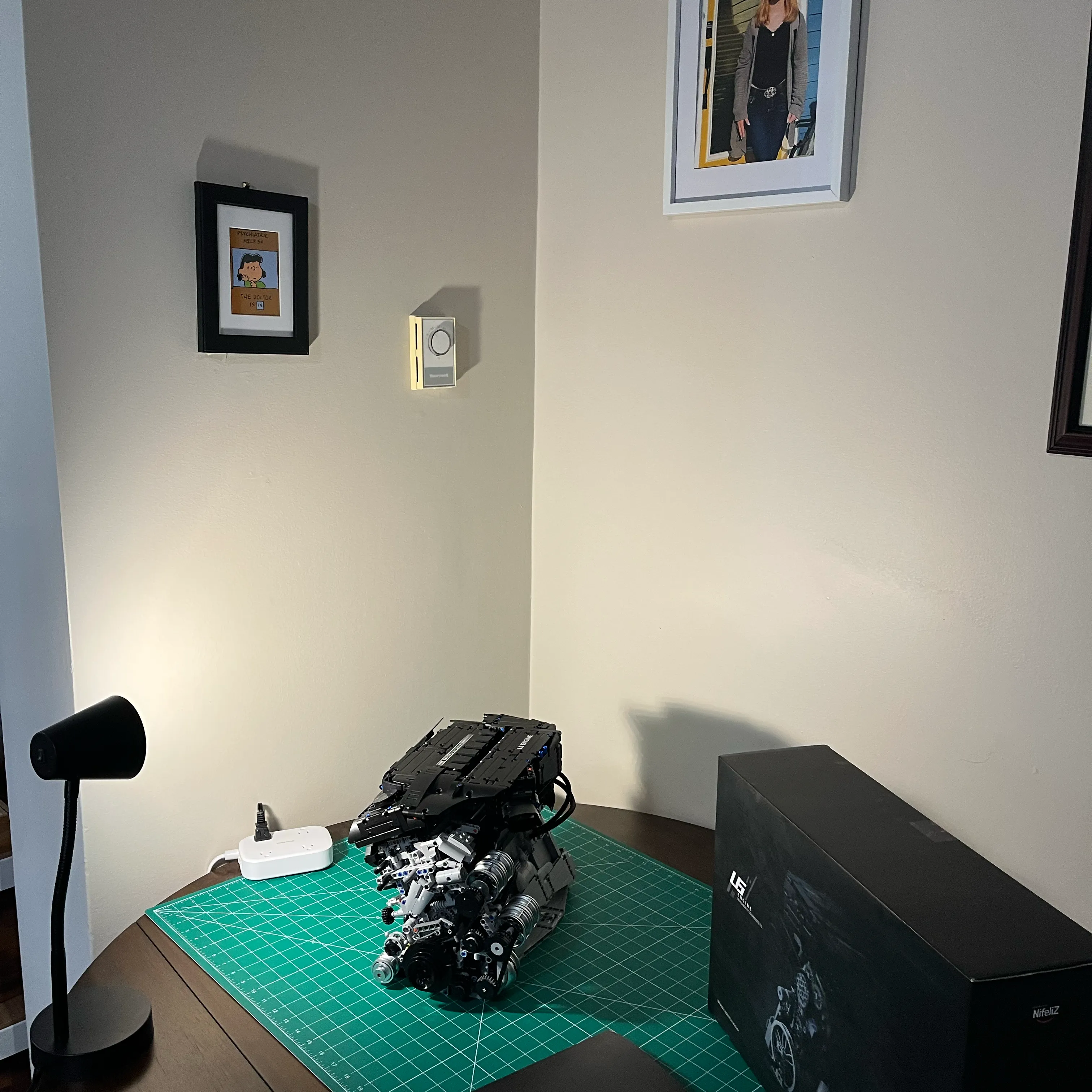
Below is a teardown and detailed walkthrough of my redesigned cam drive system for the NifeliZ L6 Model engine I built. See my posts NifeliZ L6 Model Engine and Photos of the NifeliZ L6 Model Engine Build to see the stock build time-lapse and troubleshooting of issues that came up.
I purchased the NifeliZ L6 Engine kit on Amazon for $140 CAD ($100 USD). If you’re interested in the kit, check out the NifeliZ L6 Engine Website and the YouTube Promo Video.
Cam drive system teardown
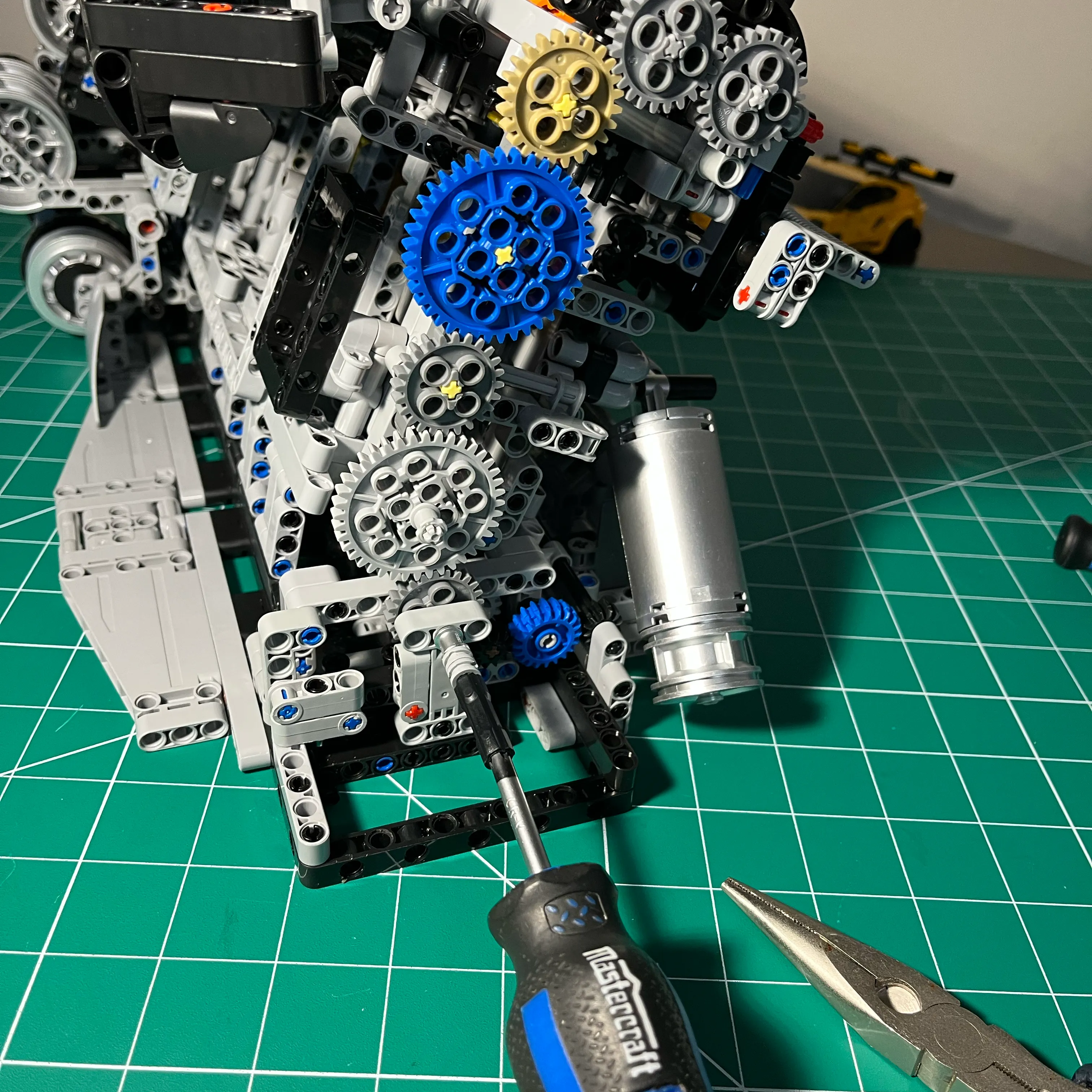
Assembled cam drive system, with screwdriver attached to crank
Pic of the redesigned cam drive system that I’m going to tear down to document the design. I used a small screwdriver to rotate the crank while inspecting it for clearance issues.
For reference, here is the stock build, which uses 2 plastic chains.
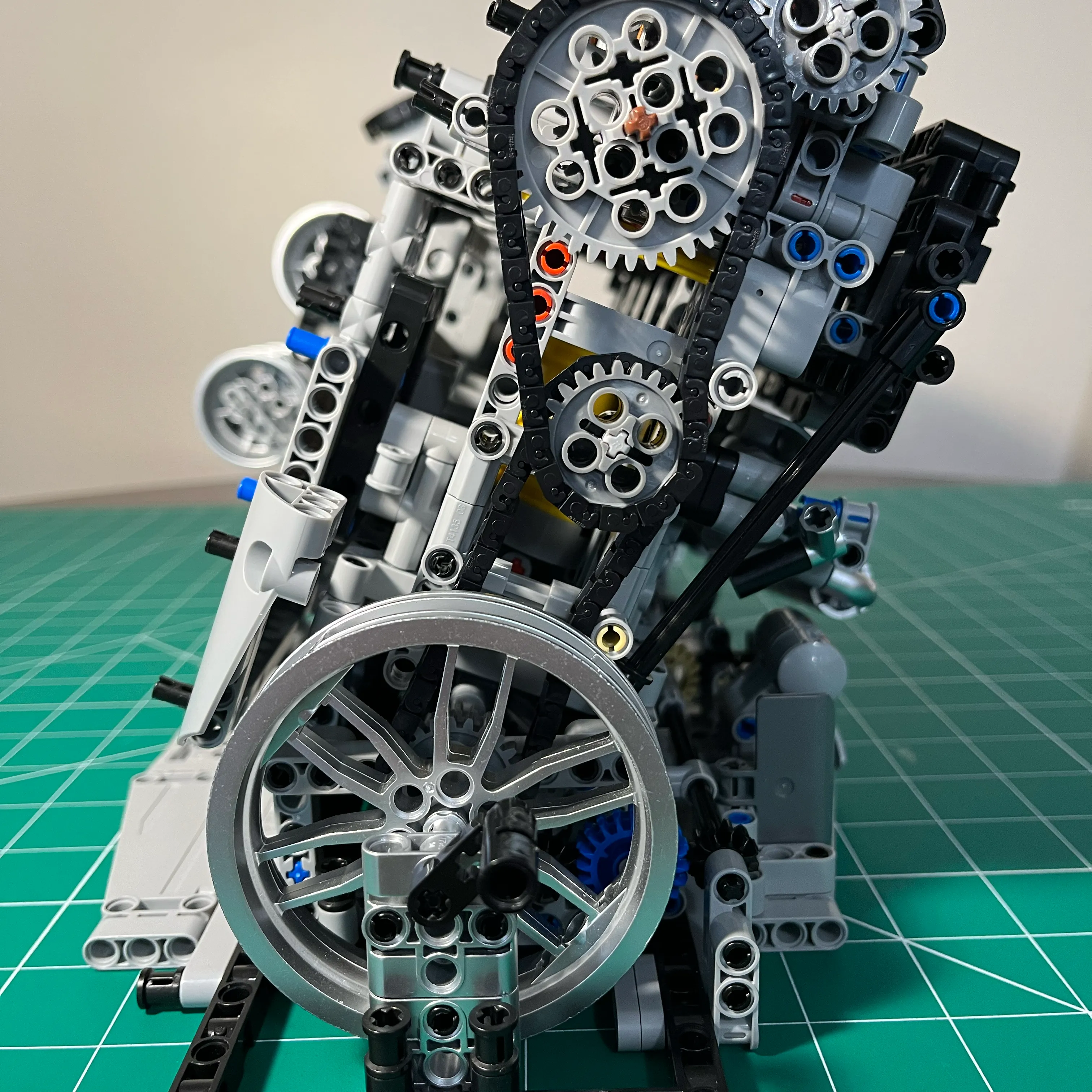
It looks pretty, looking at it straight on. Now look at the side view, and see the flex that happens when enough tension is applied to keep the chains from skipping.
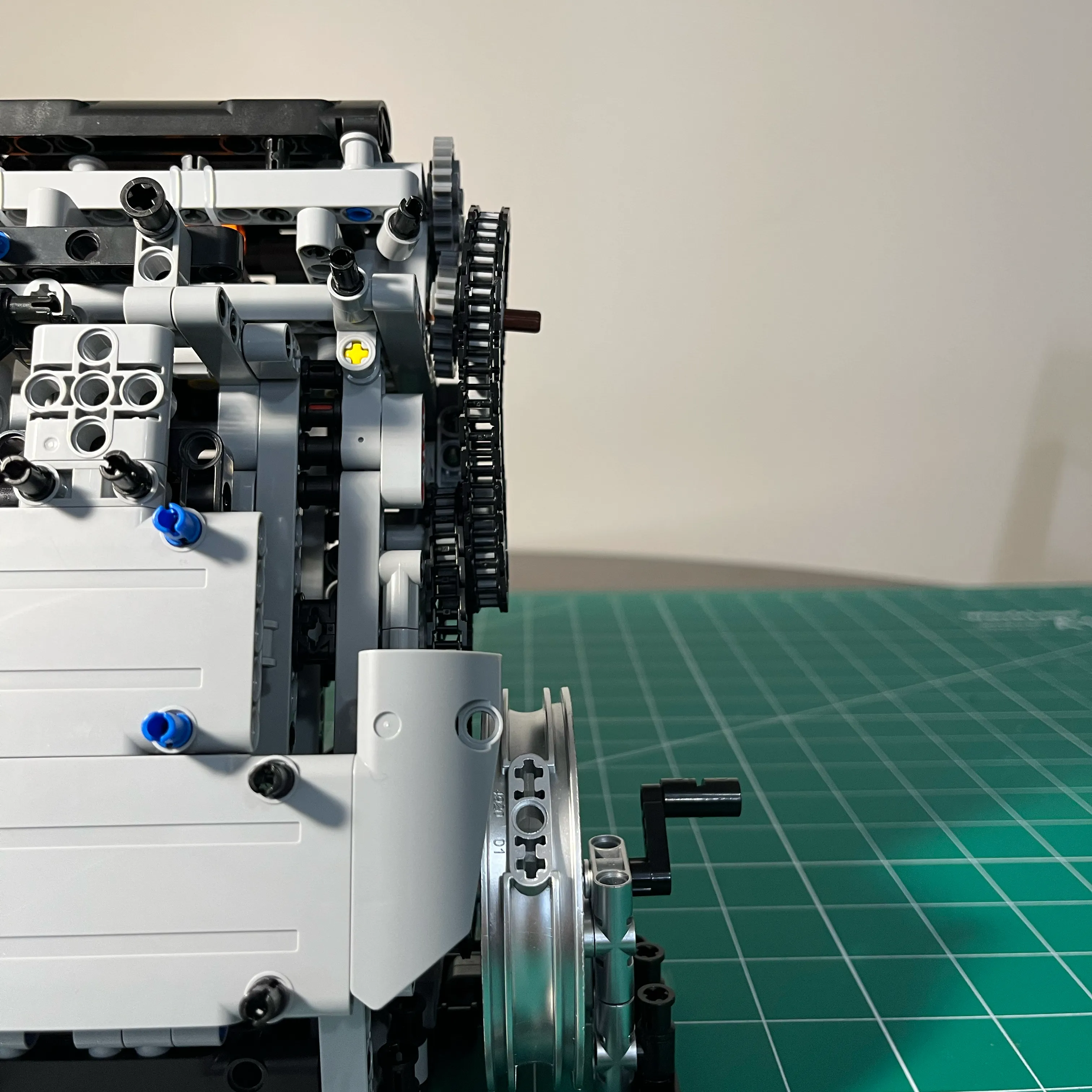
I didn’t want a show piece that was all show and no go. I want to be able to spin this over without the chains coming apart or the cams not turning with the crank.
Gears Removed
View of the rear of the engine with all gears removed, excluding the crank gear. This gives a view of the structure of my redesigned cam drive system.
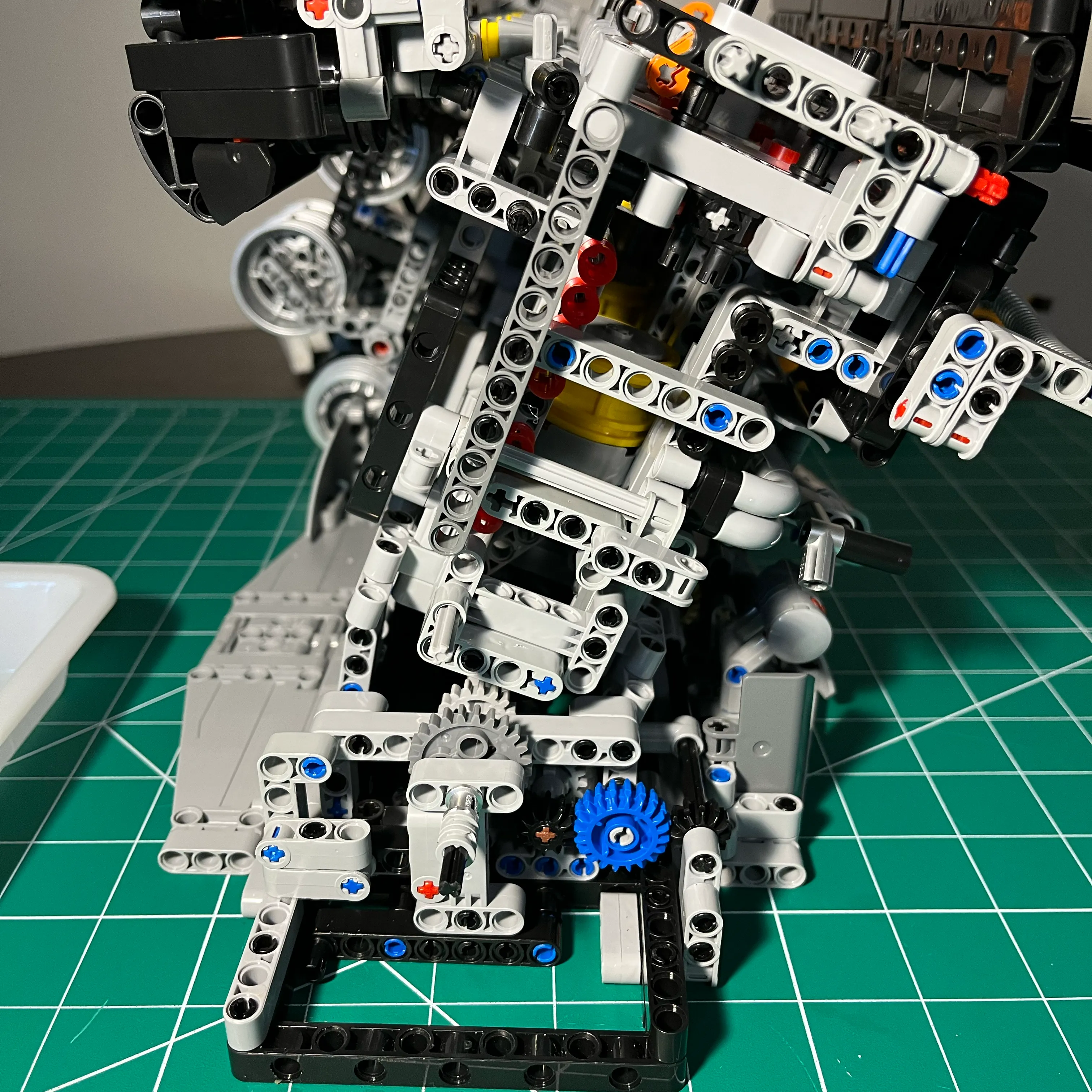
Crank Collars Removed
These collars on the crank add additional friction to help prevent the crank from protruding through the crank lobes in cylinder 6. That problem has caused me many headaches, so preventing that problem, especially while using a drill to spin the engine over will help minimize the amount of time I spend reattaching the piston to the connecting rod in cylinder 6.
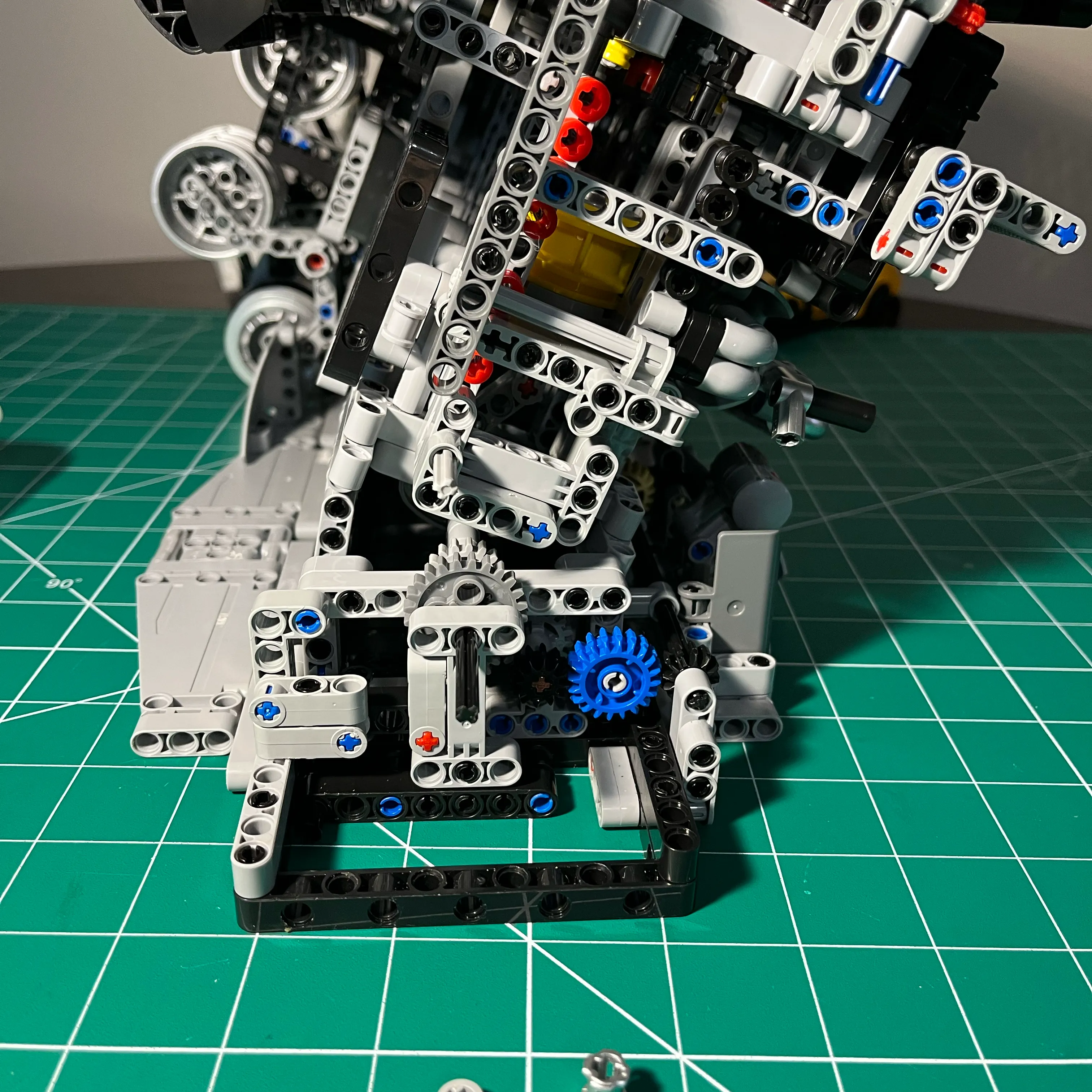
Crank Support Assembly Removed
The crank support assembly helps to reinforce the crank from moving while rotating the crank with the wheel that comes with the kit. The small hand crank that comes with the kit is too short, and using it causes excessive flexing of the cam drive system. Turning the engine over by using a lever increases the amount of flex. Using a drill to turn the engine over helps to reduce unnecessary flex by keeping the torque perpendicular to the crank centerline.
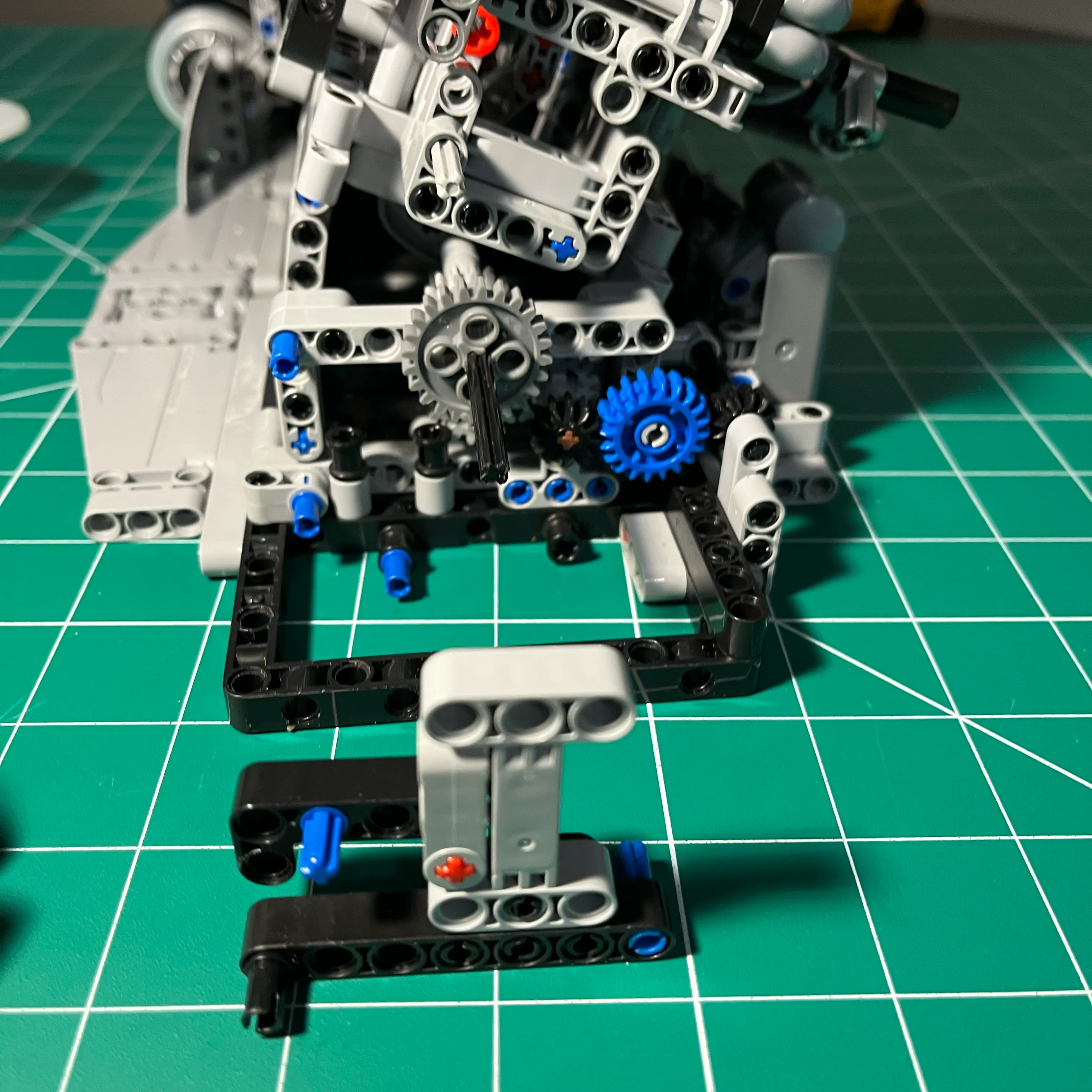
Cam Drive Gears Assembly Tensioner Disconnected
The axel spanning from the left-side to right-side engine walls provides just enough tension to keep gears meshed without skipping.
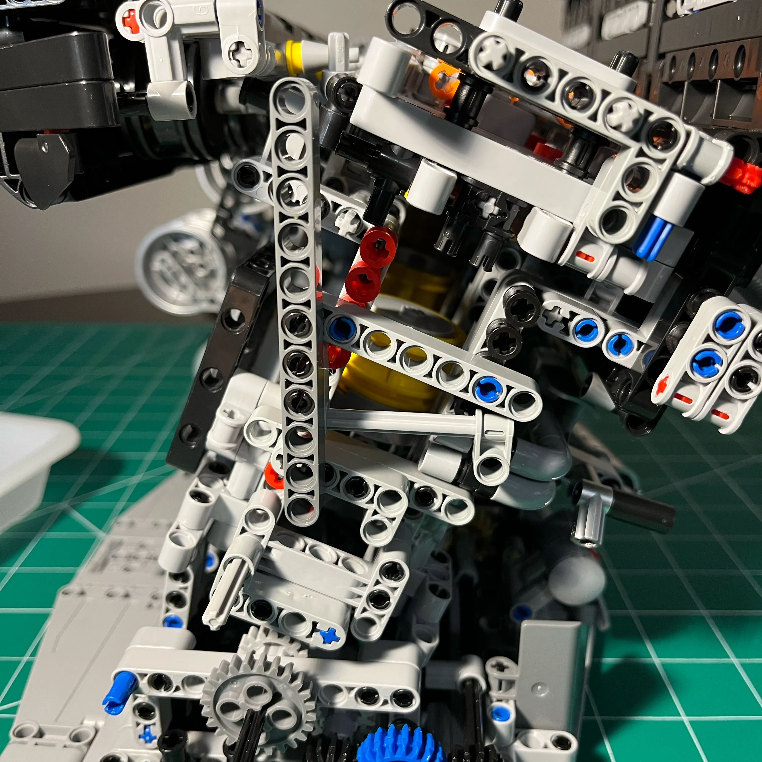
Cam Drive Gears Assembly Removed
Removing the cam drive gears assembly gives a good look at the 3 support braces. While the structure is minimal, it provides enough rigidity and also gives better visibility of the pistons, connecting rods, and crank.
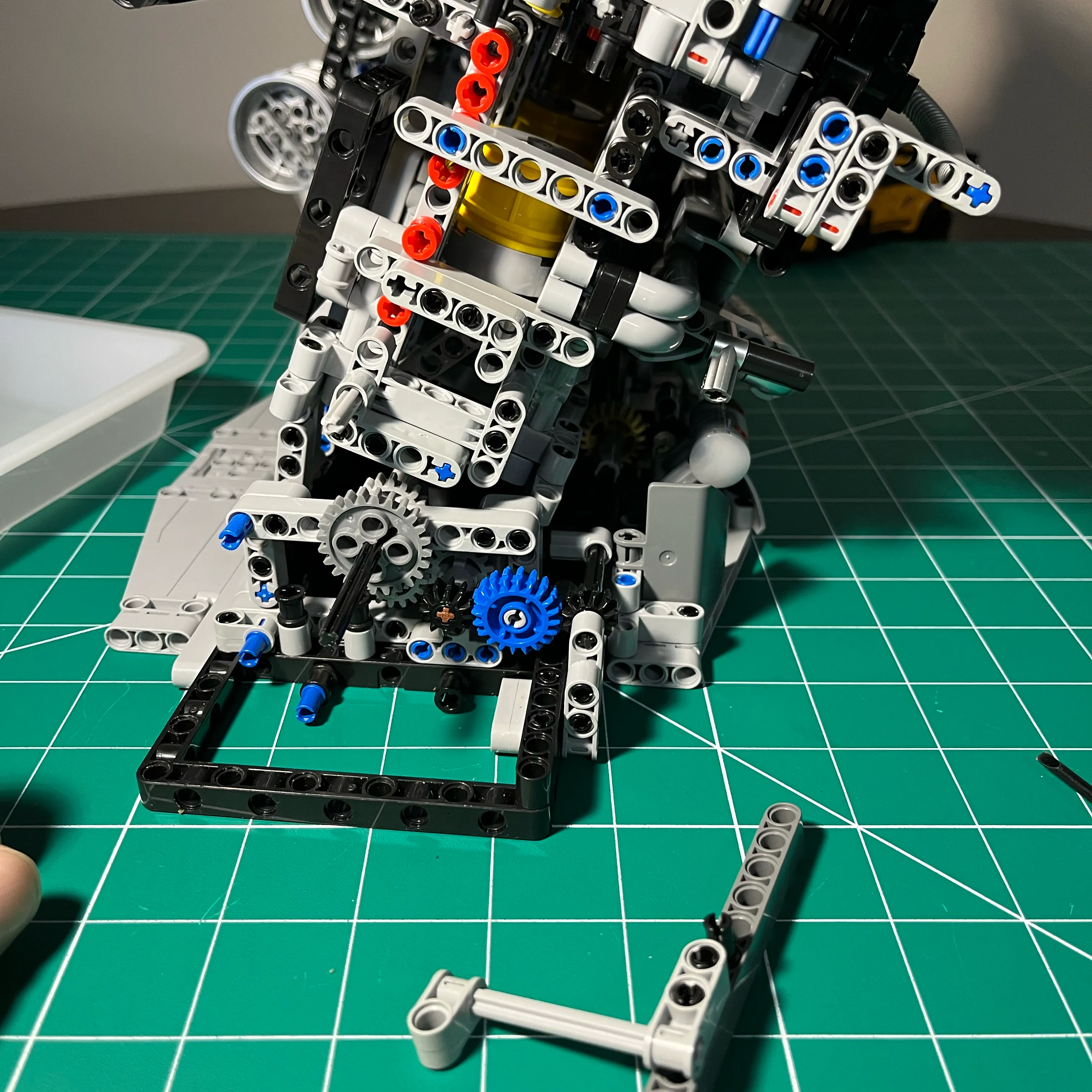
Cam Drive Gears Assembly Support Structures Removed
Removing the remaining cam gears assembly support structures gives an unobstructed view of the rotating assembly.
The red pins on the left-side wall of the engine block are visible. These pins did not come with the L6 Engine Kit - they came from the 582pcs Technical Parts and Pieces Beams Axles Connectors Bricks Set I ordered from Amazon. I also ordered 184PCS Gear and Axle Set for Technic Parts to have enough parts to replace both plastic chains with gears.
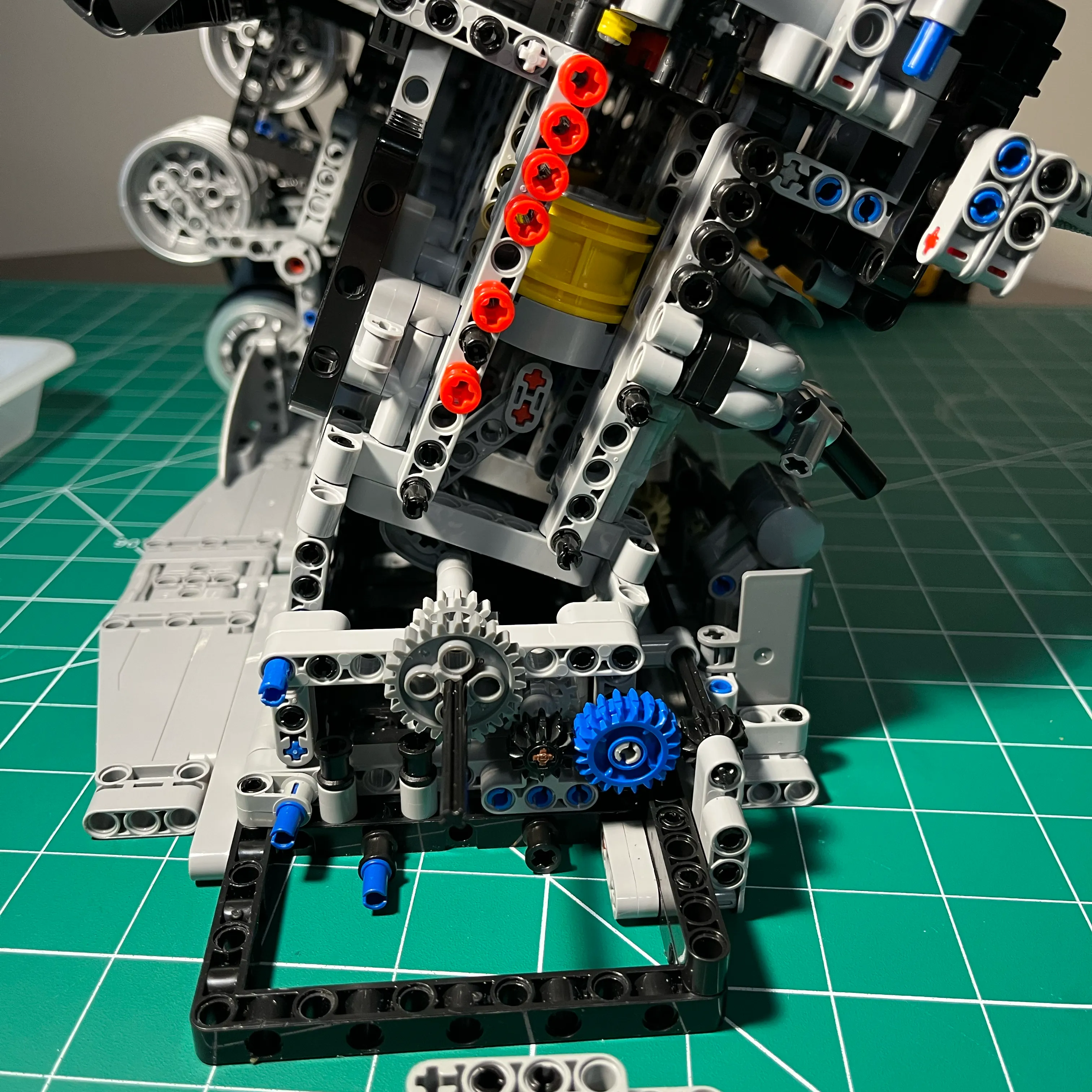
Having full view of the rotating assembly, I recorded a quick clip of spinning the engine over with a drill.
Then I got really excited and turned the engine over a little too fast, resulting in the cylinder 6 piston detaching from the connecting rod. Send it! To the moon!
Crank Gear Removed
Removing the crank gear completes the tear down of the rear of the engine. All the remaining structure is stock.
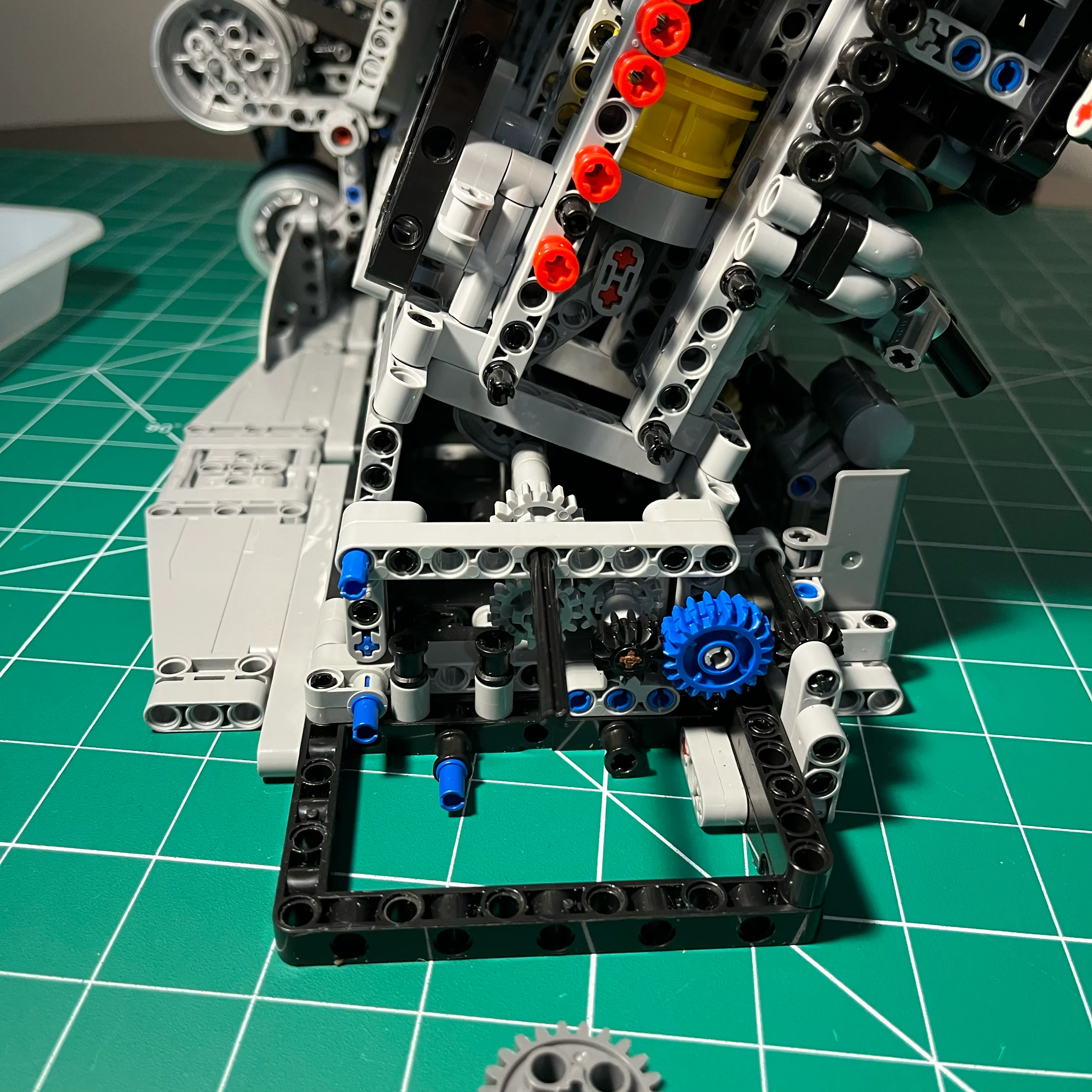
Teardown Complete
To properly document this redesign, I performed a full teardown of the working model. This “reverse-engineered” view shows the engine block’s rear face, cleared of all timing components and ready for the new gear-driven architecture.
Torn down rear engine viewed straight on
Clear view of cylinder 6 piston, connecting rod. The crank lobes are barely visible at the bottom of the left-side wall of the engine block.
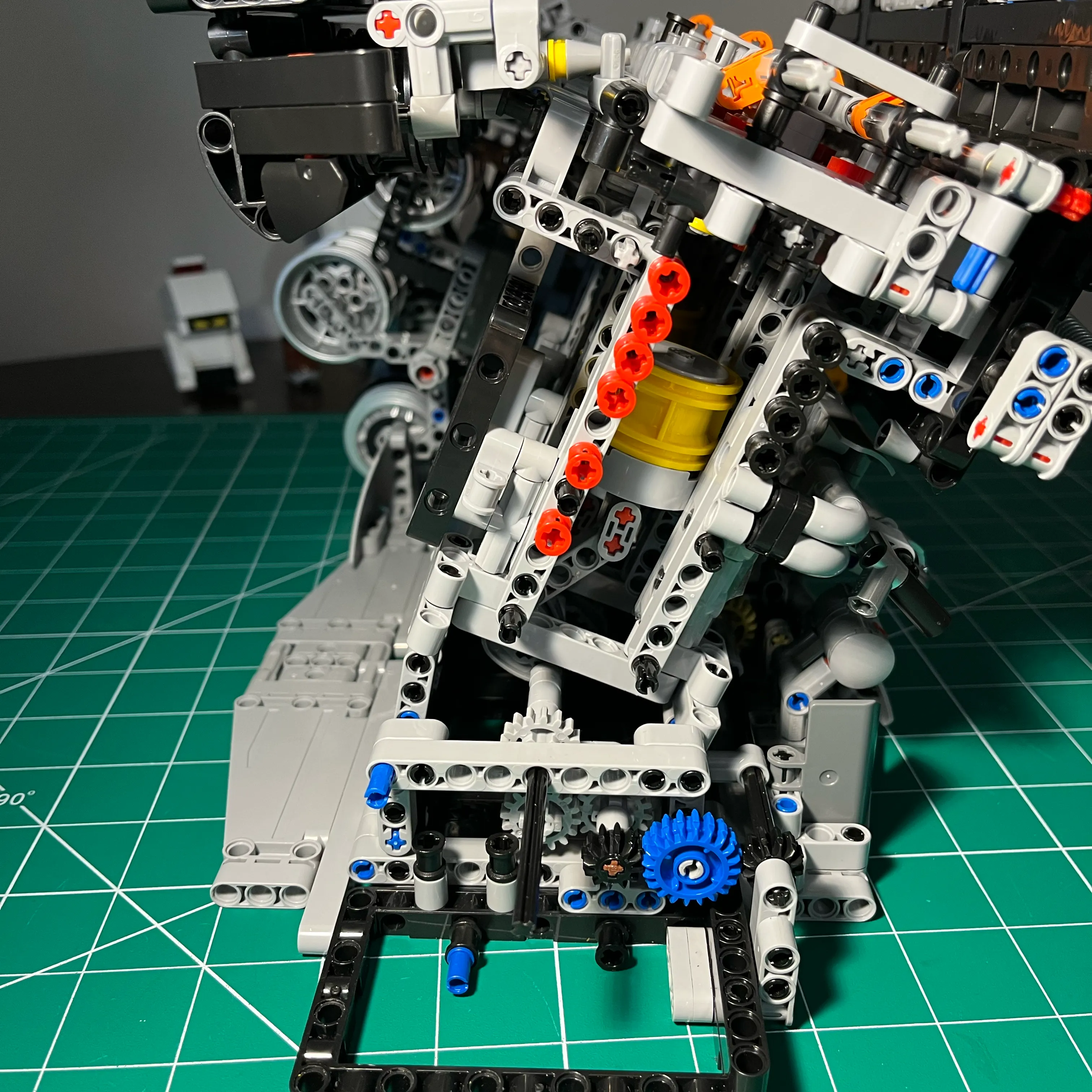
Torn down rear engine viewed at an angle from left side
I’ve removed the panels from the exterior of the left-side wall of the engine block. I did this mainly for practical purposes. Since the pistons sometimes disconnect from the connecting rods, keeping the panels off saves the headache of having to remove and replace these components. It also looks cooler, IMO. I removed some components on the back of the engine cover on the left side, since they were getting in my way. The engine cover still looks great and you wouldn’t know at a glance I had changed it.
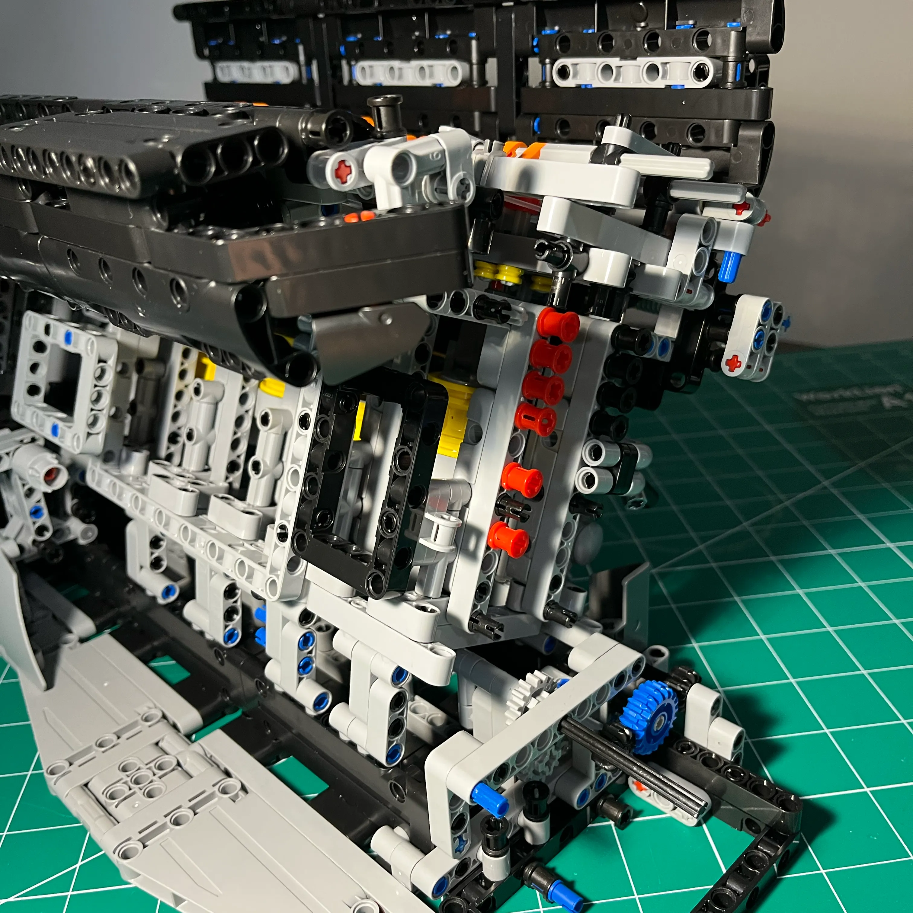
Torn down rear engine viewed at an angle from right side
Not many changes on the right-side wall of the engine block. I think the only thing I did here was change the connection point of the gray plastic tube. The rest of the exterior components on the right-side wall of the engine block are stock.
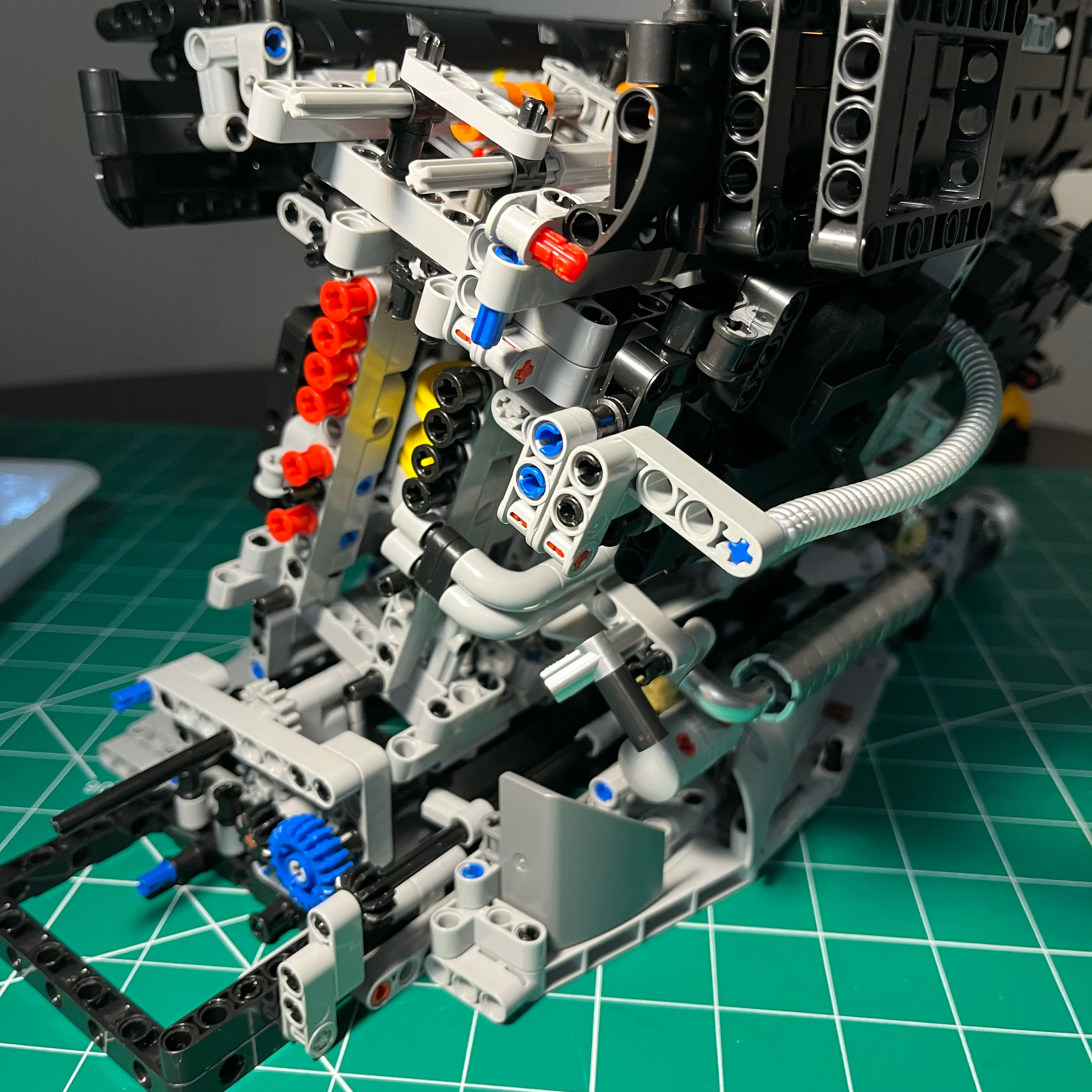
Rebuilding Cam Drive System
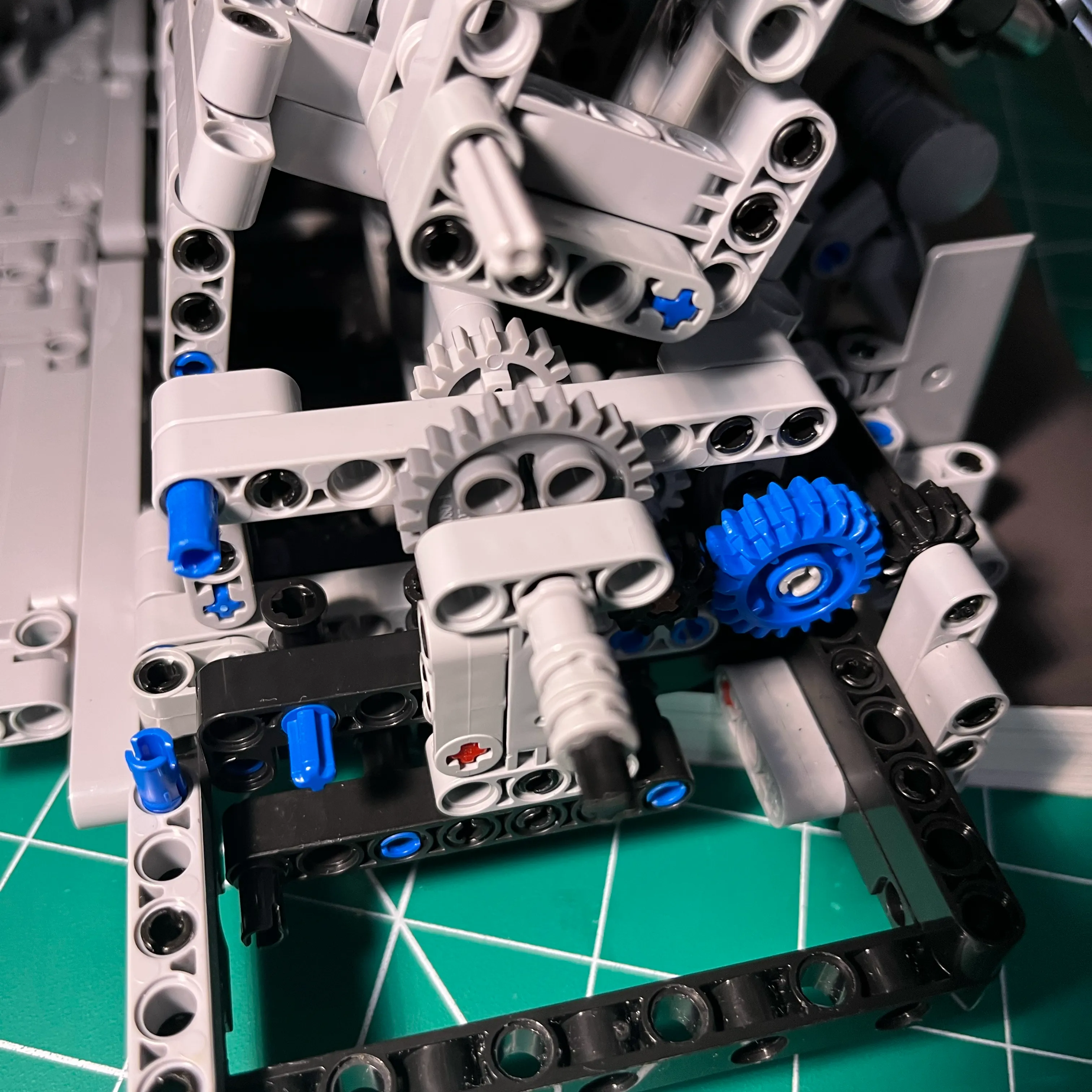
Replacing red mockup support pins with black pins from L6 Kit
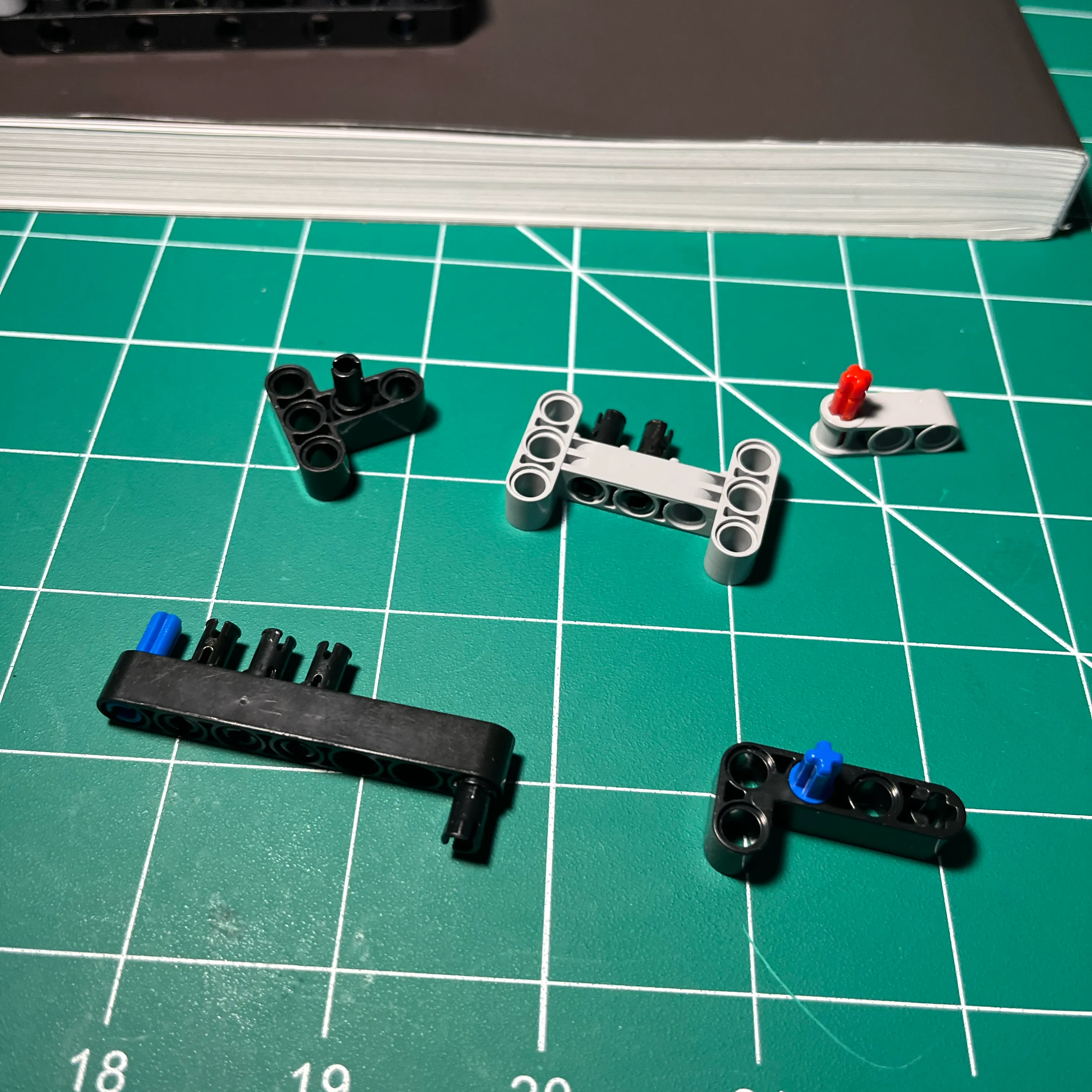
When I was mocking up the all gear drive, I was using a new pack of these red pins that push through 2 Technic beams. This is great for rapid prototyping. Now that the prototype is complete, I swapped out the red pins for the black ones that originally came with the kit.
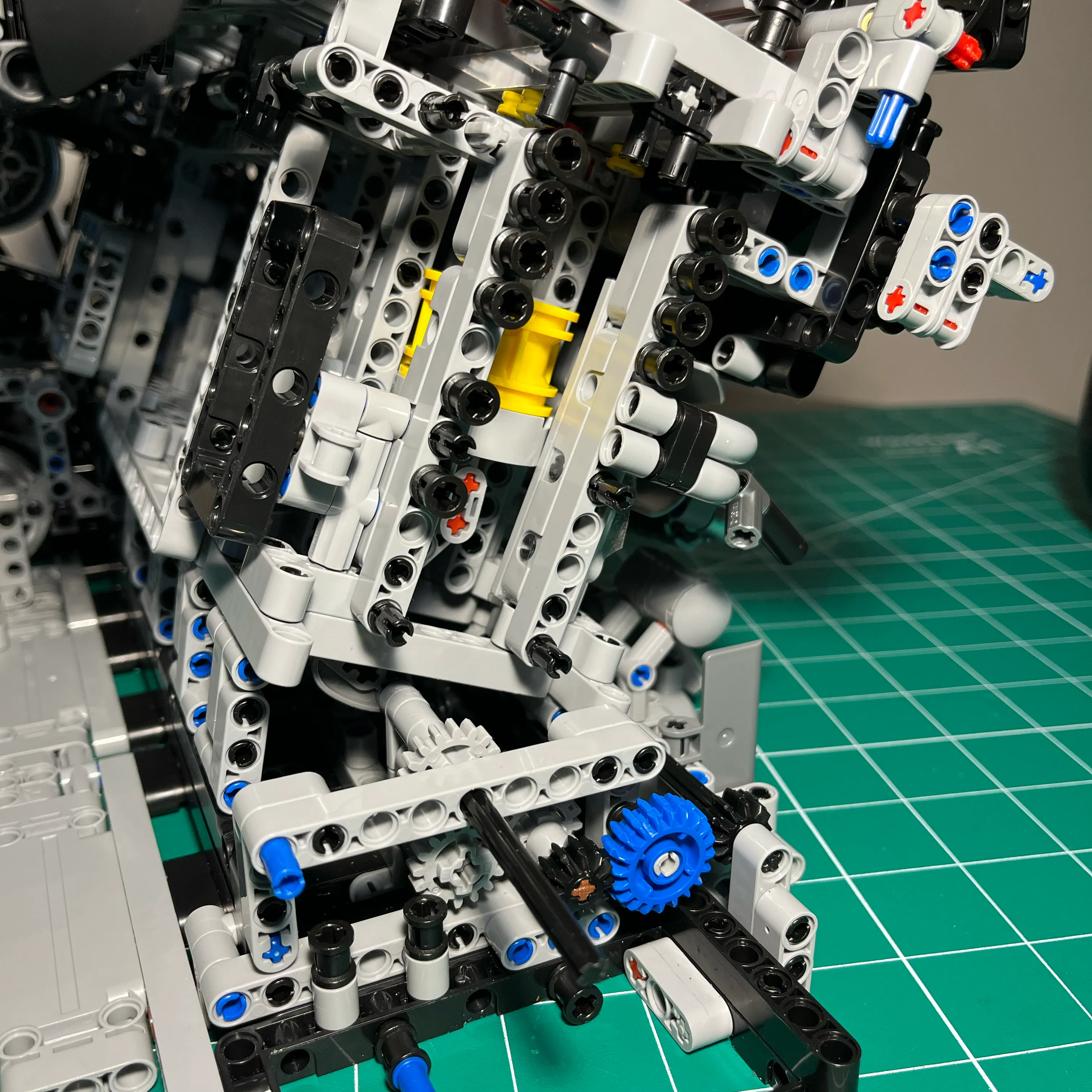
Support Structure for large light gray gear
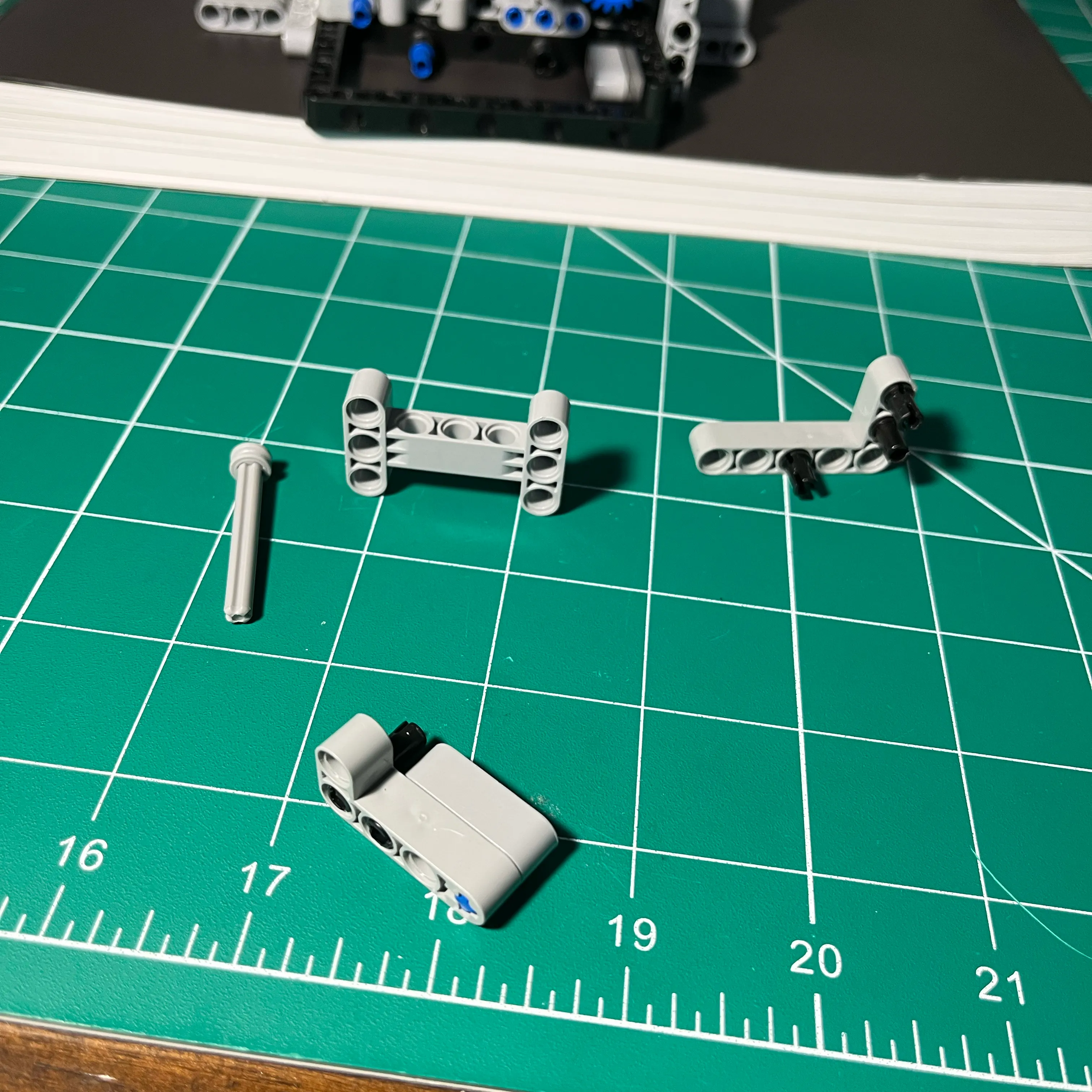
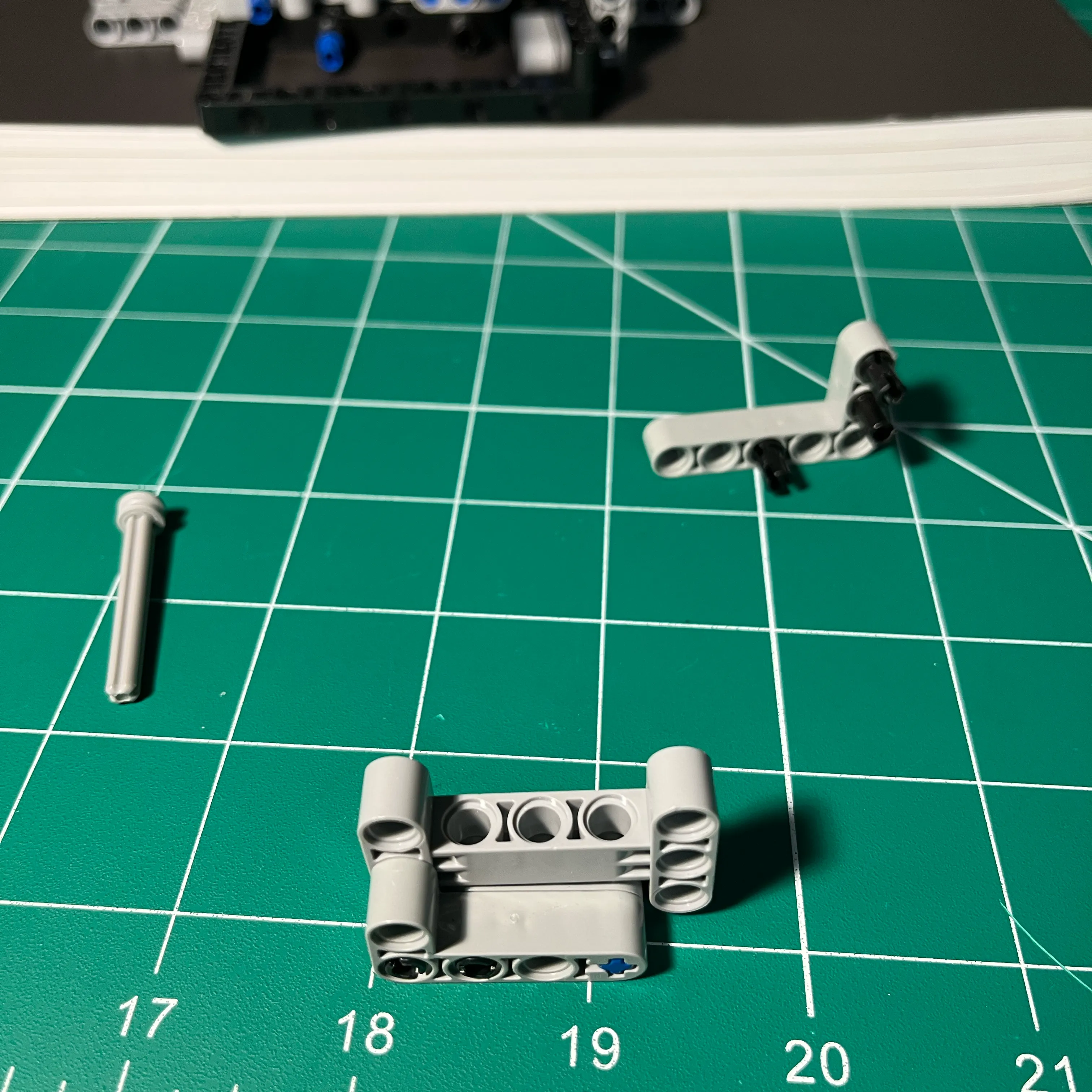
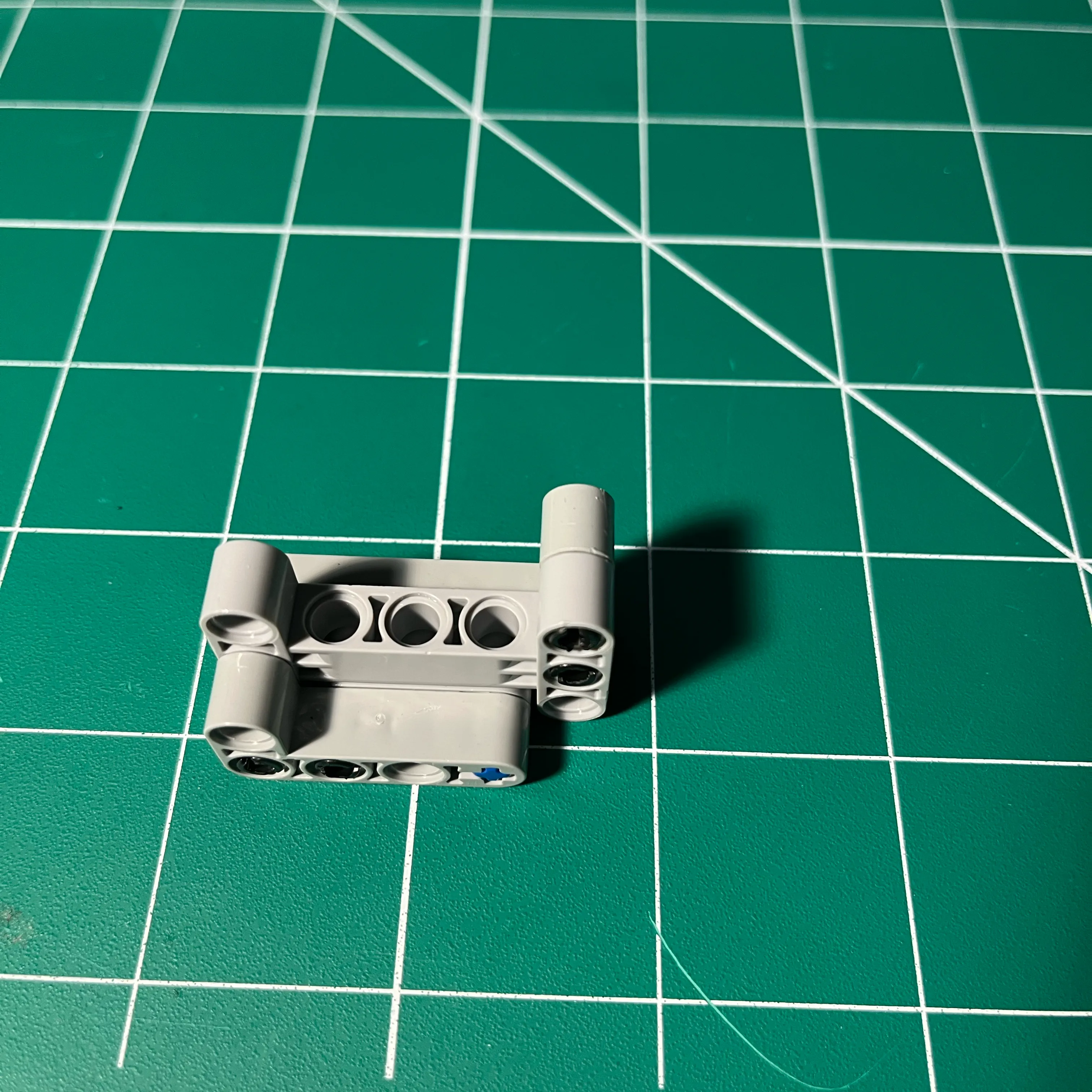
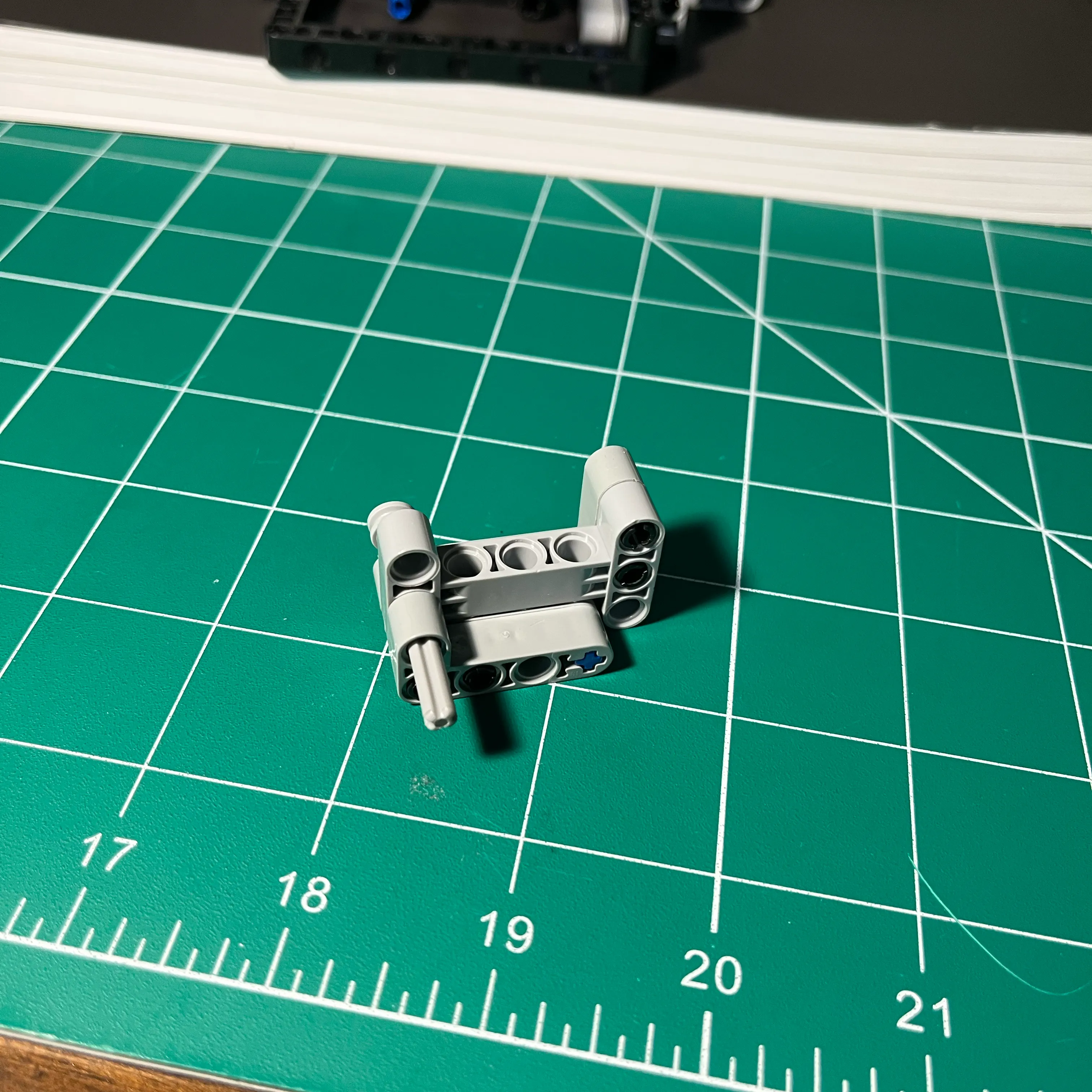
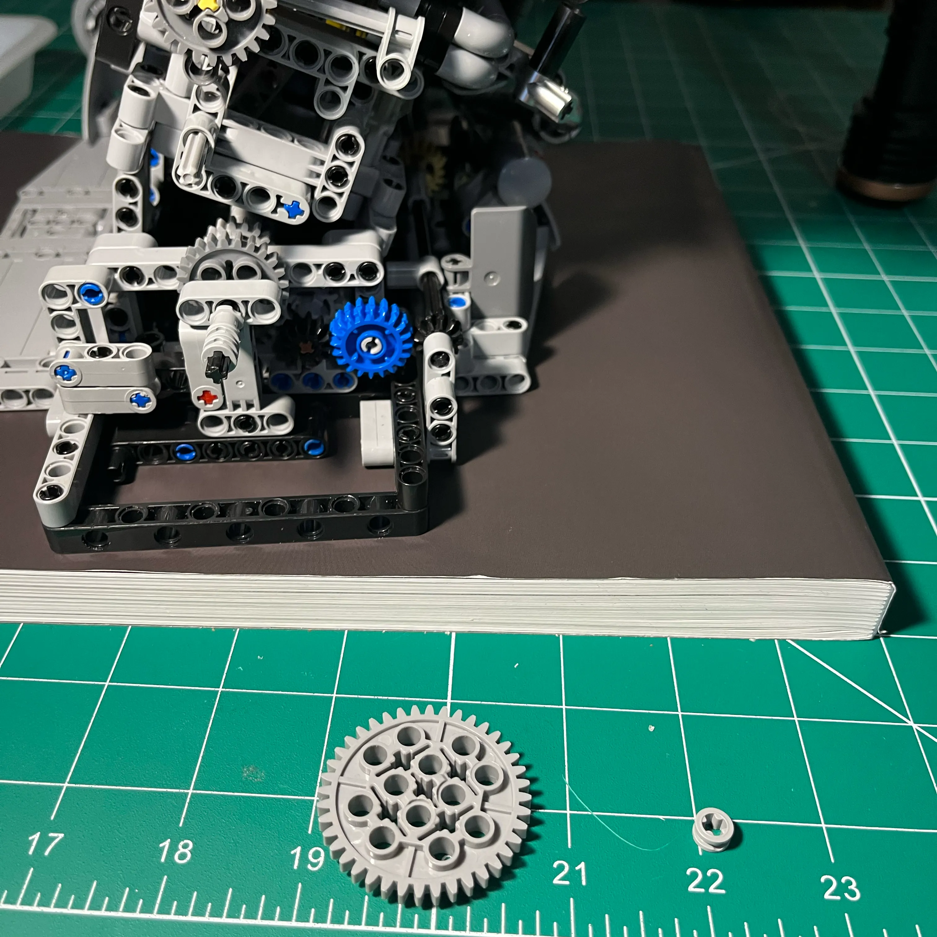
The large gear that meshes with the smaller crank gear needs to be very rigid to handle the rotational torque. While simple, the stock connectors don’t offer much lateral stability. I found that using a longer axel supported through two beams—secured with an adjustable collar—allows the gear to stay perfectly vertical under load. This prevents the teeth from “skipping” when the crankshaft is spinning at high speeds.
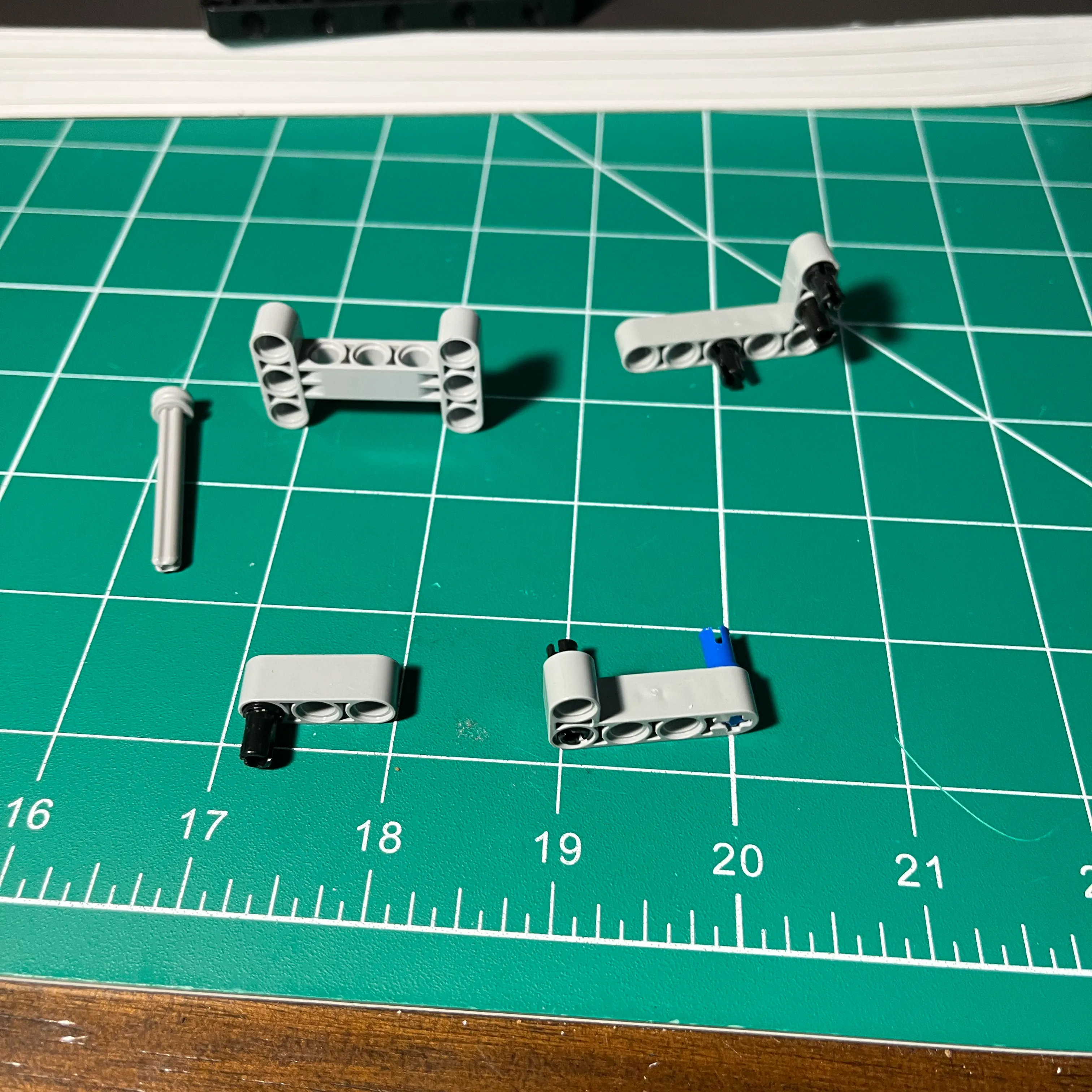
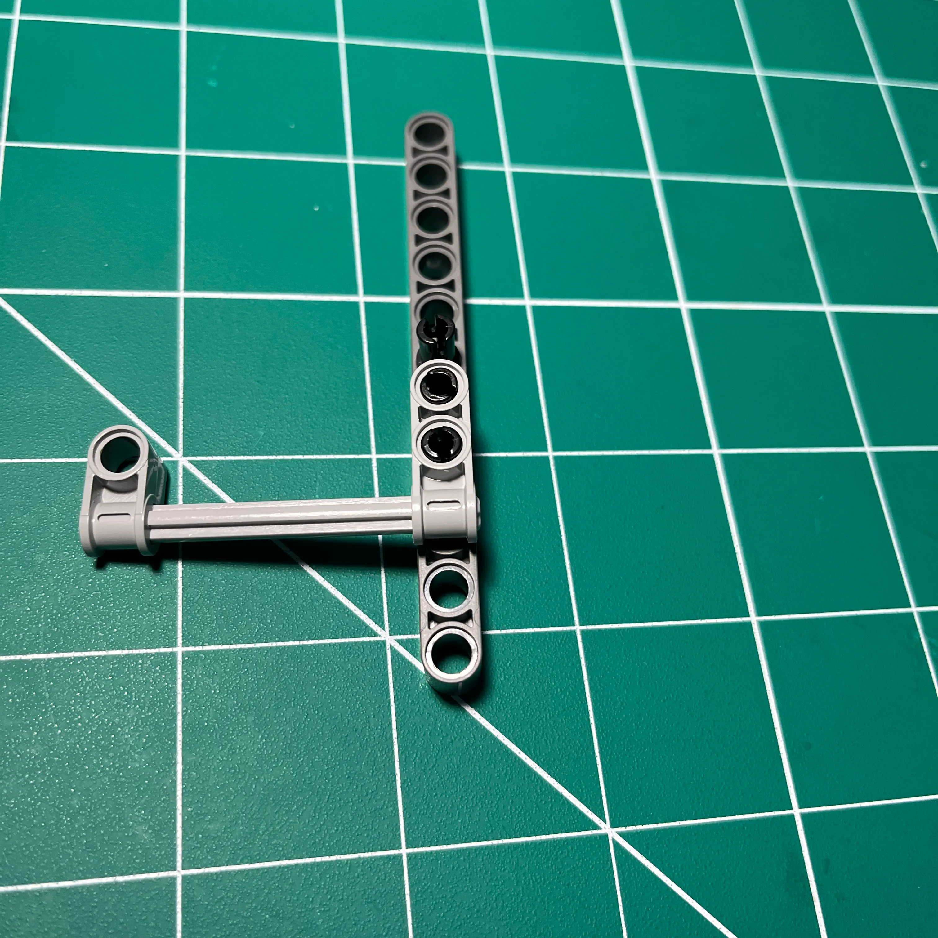
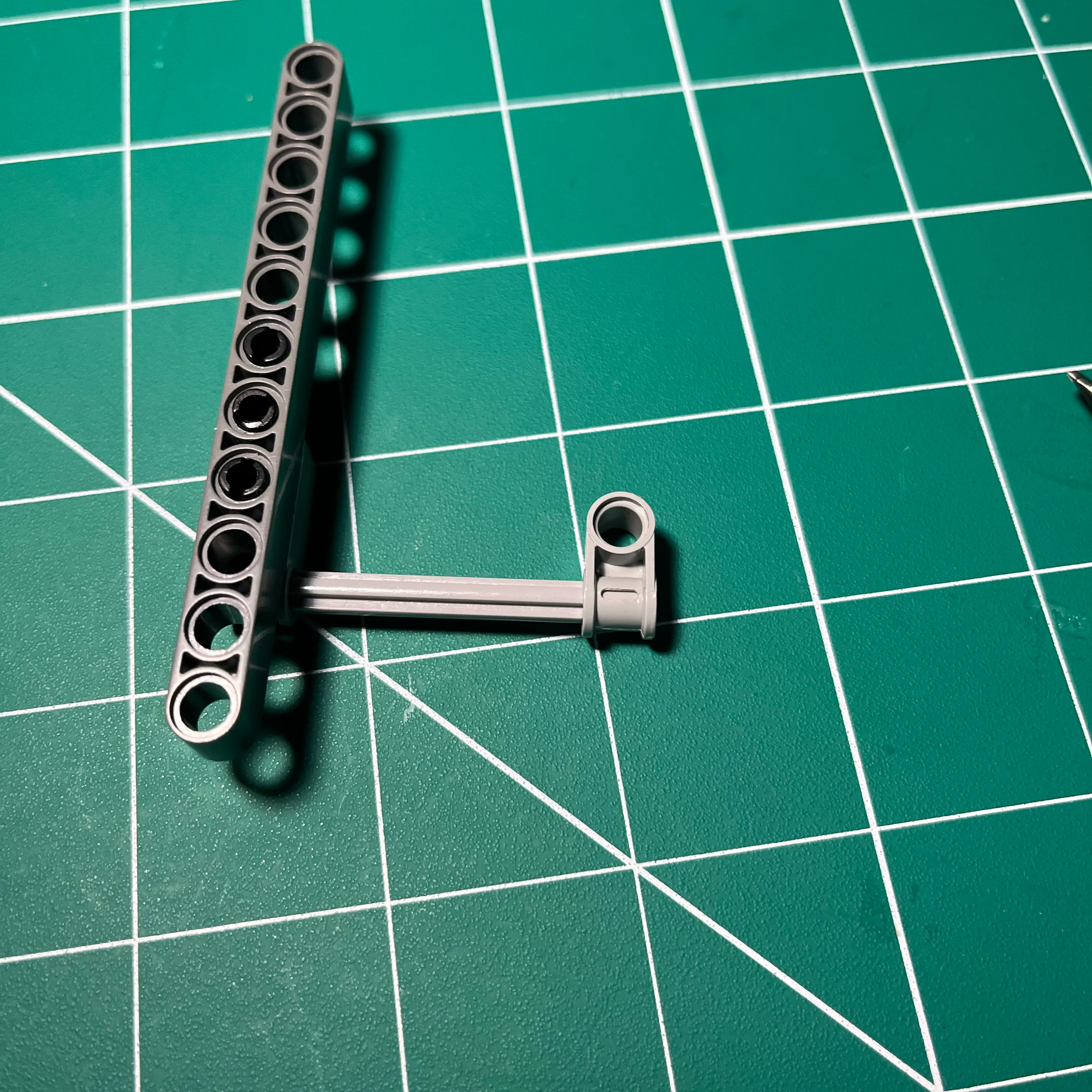
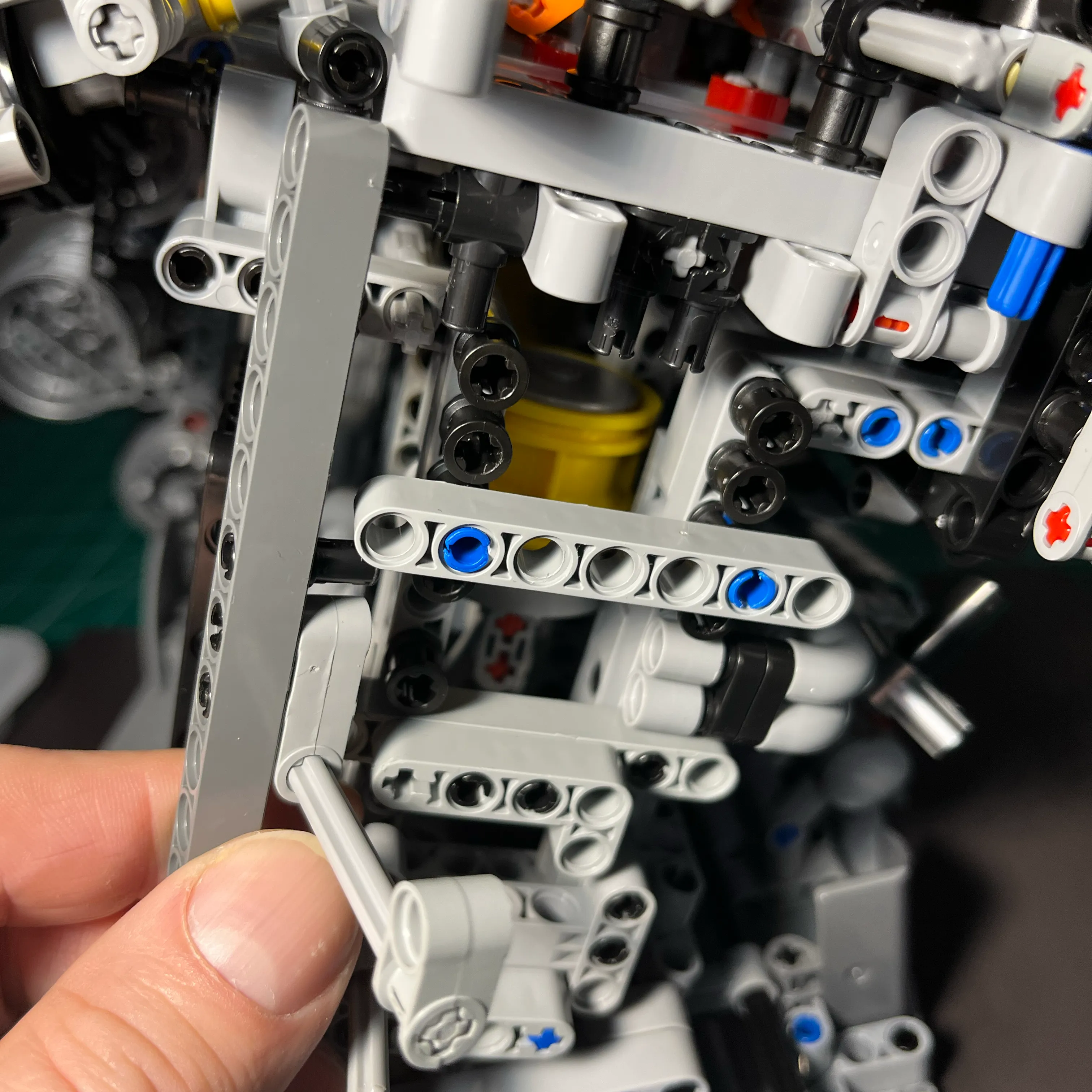
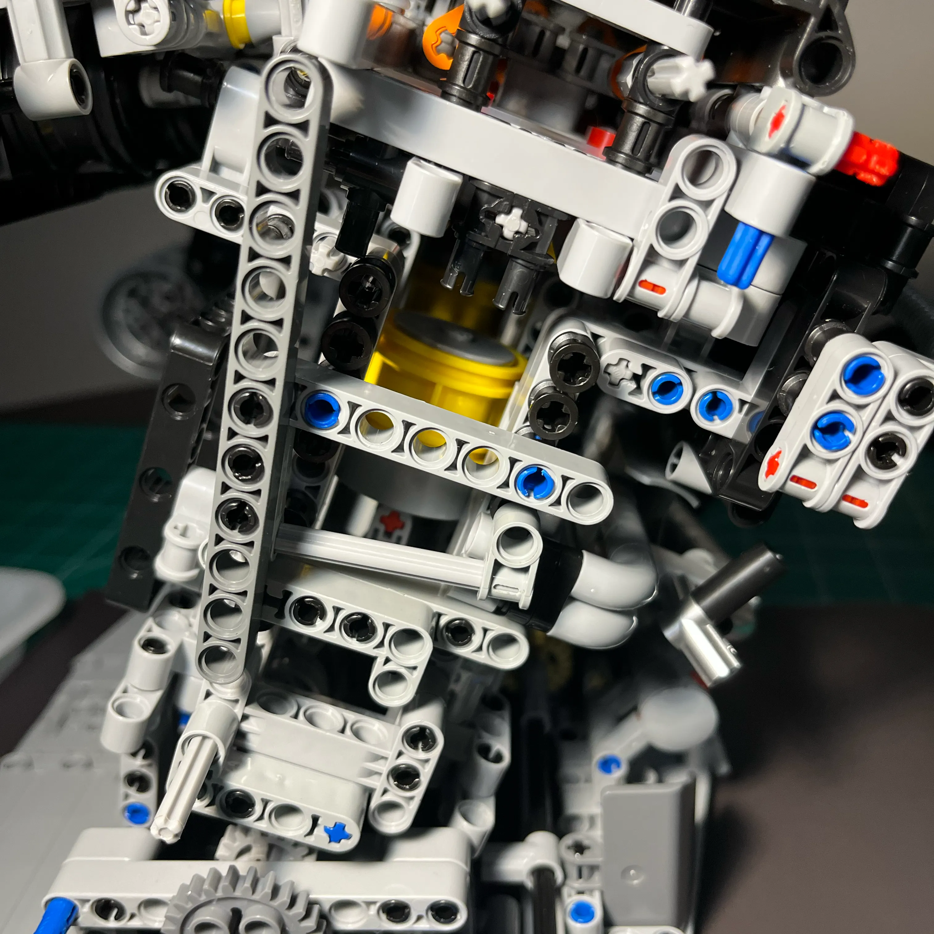
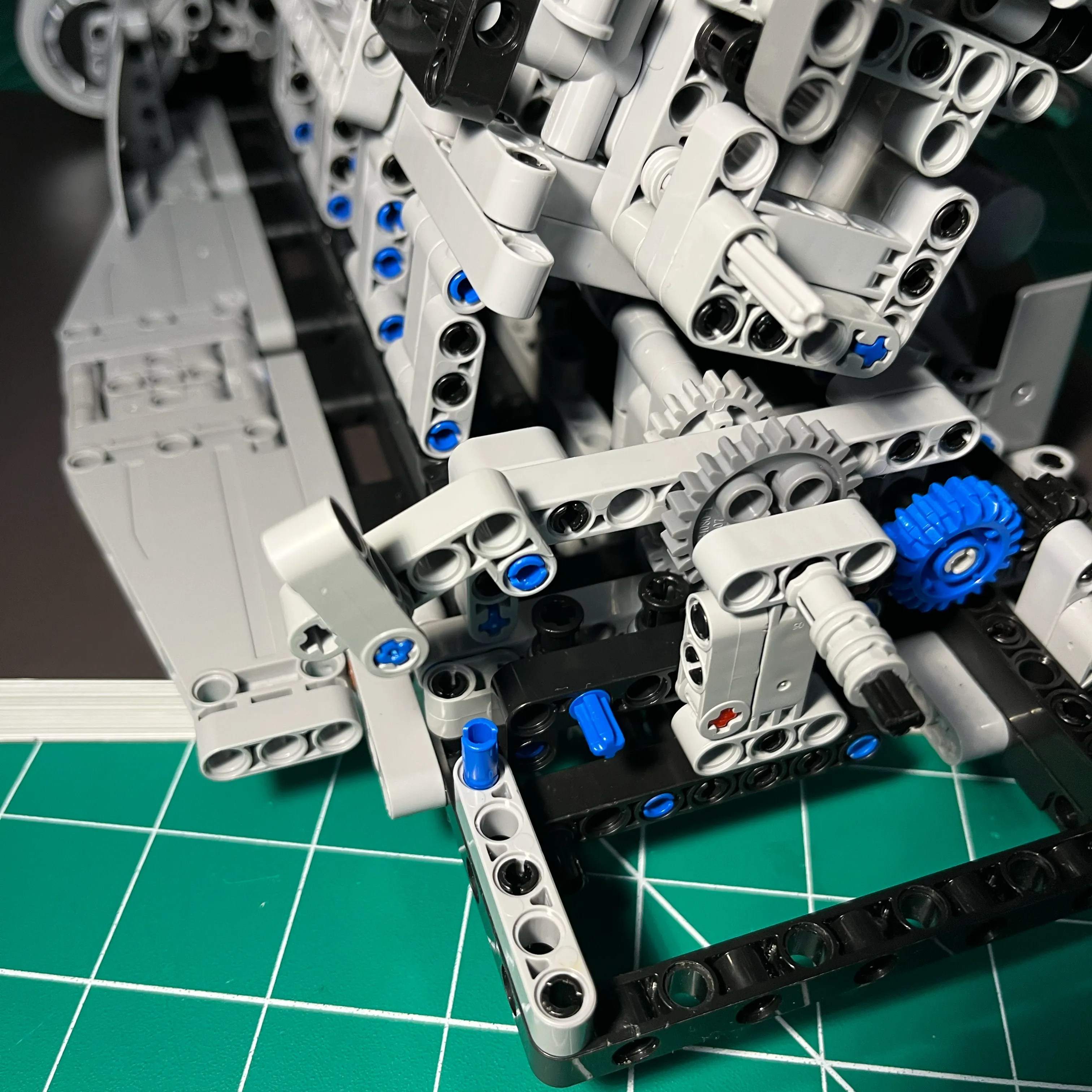
Cam Drive Gears Assembly Pivot Support Brace
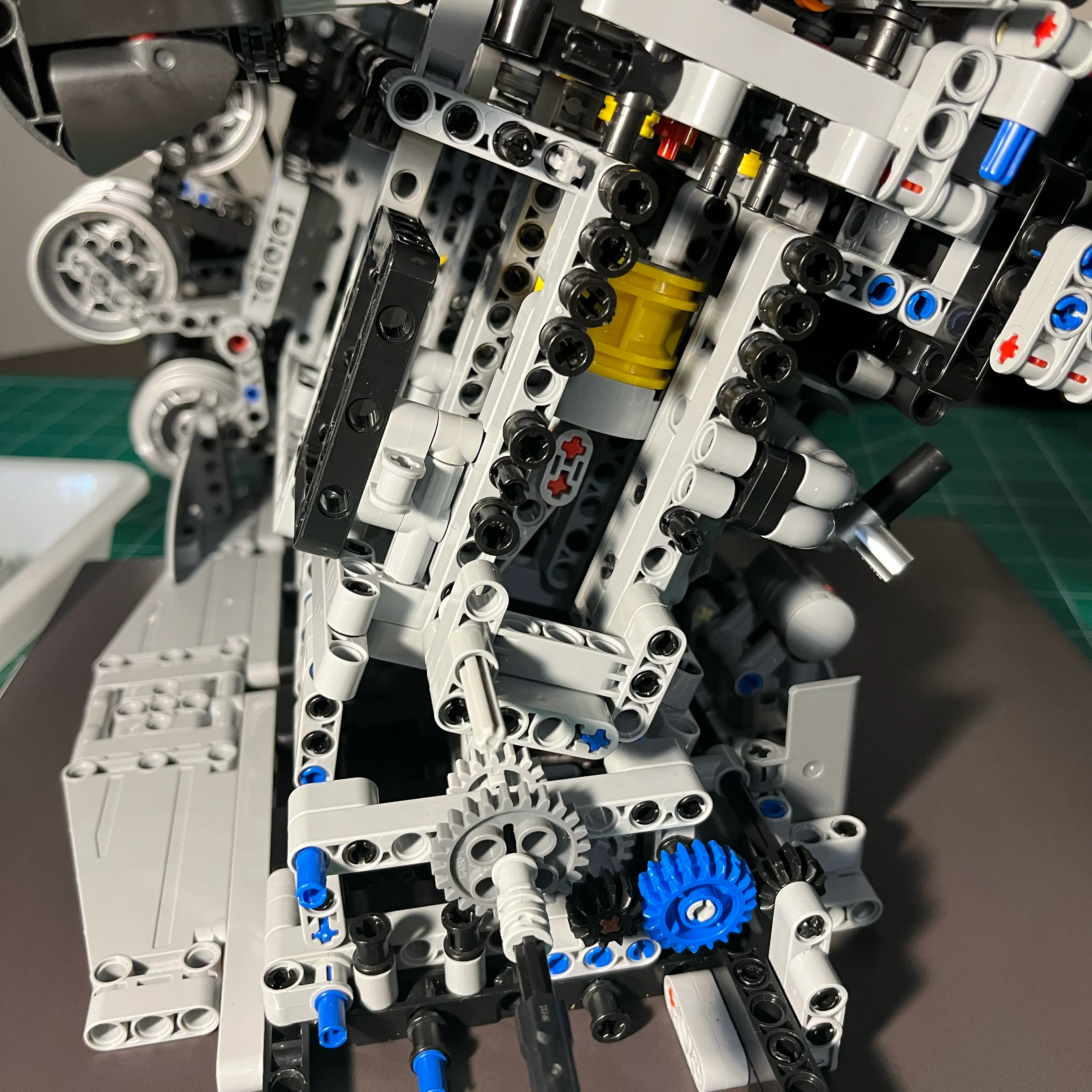
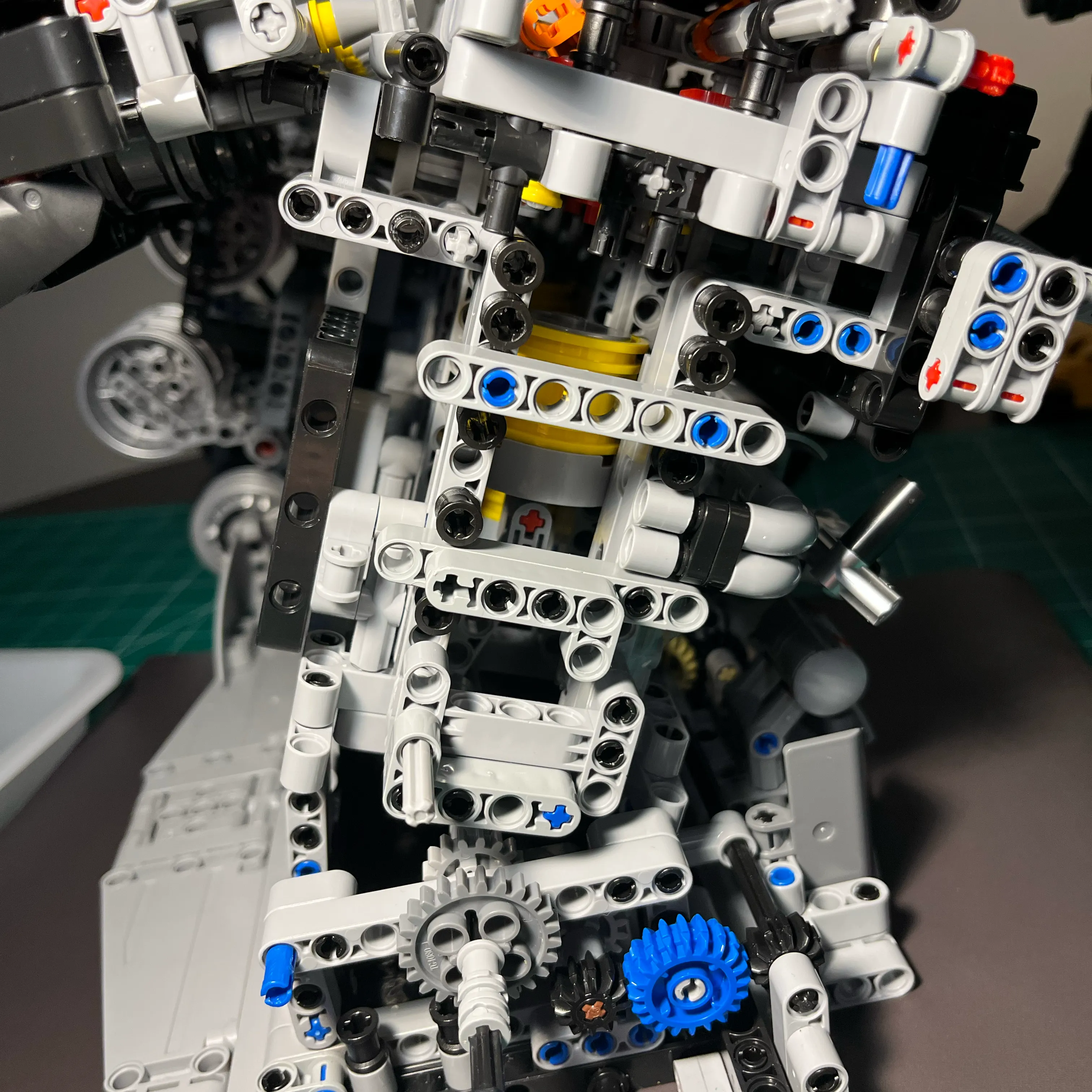
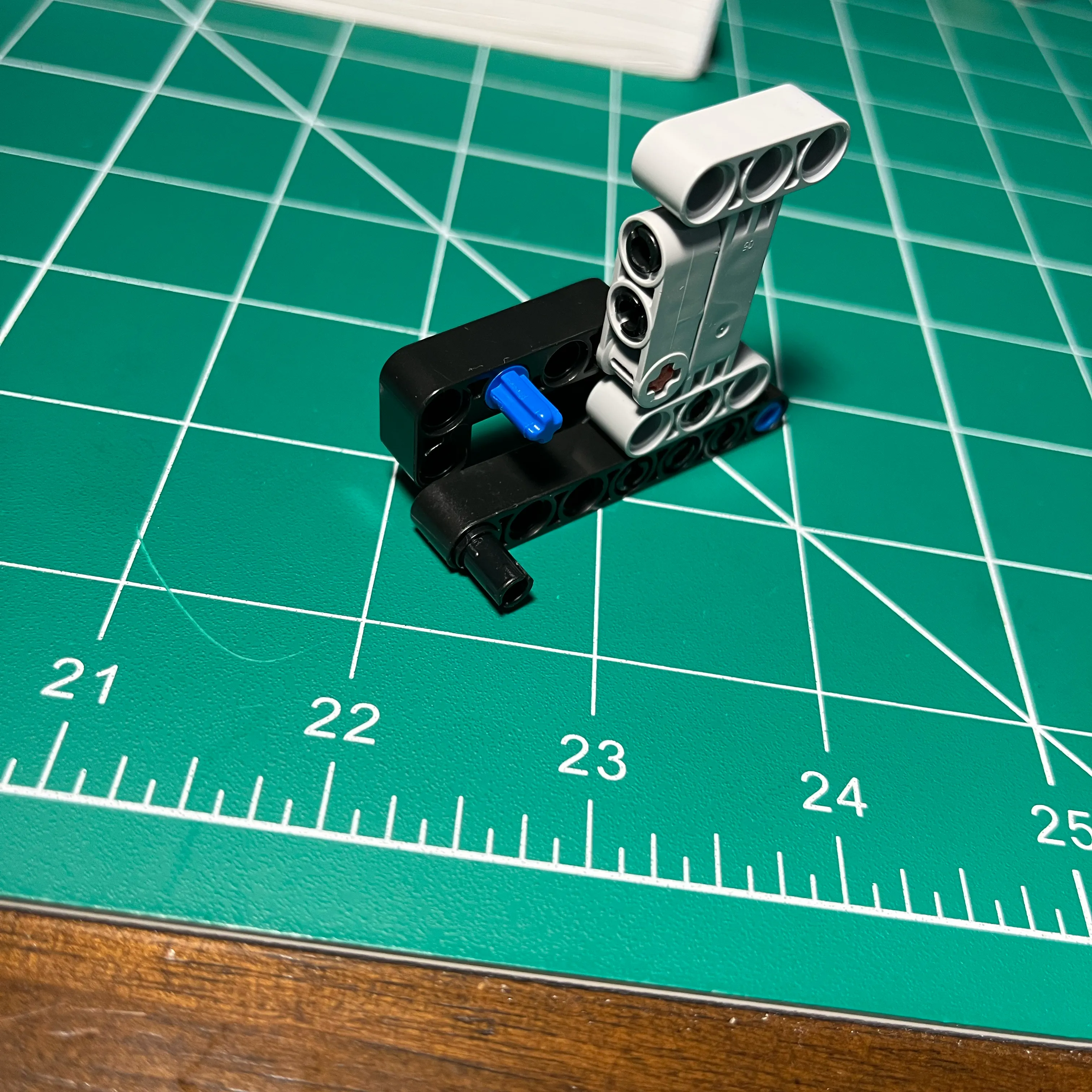
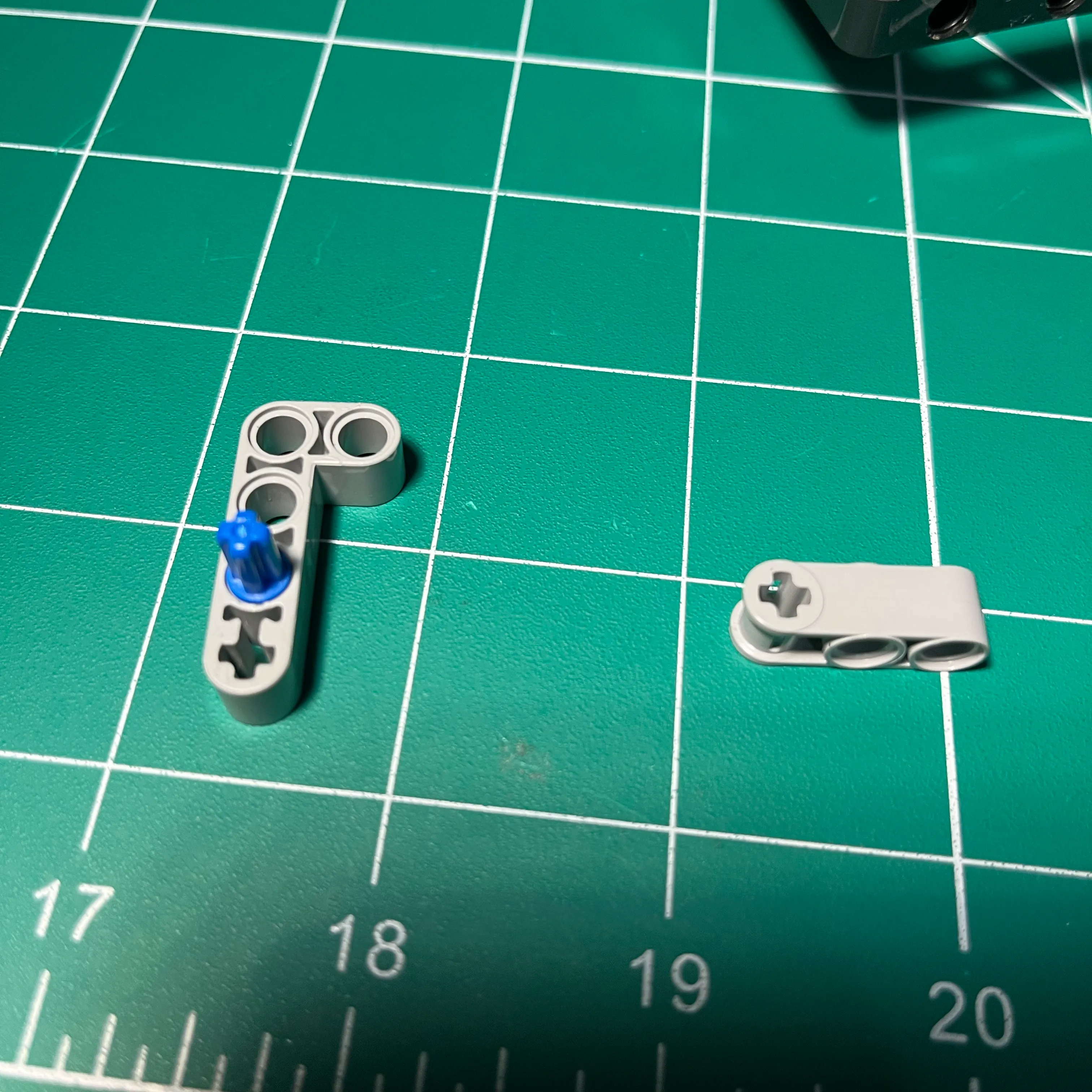
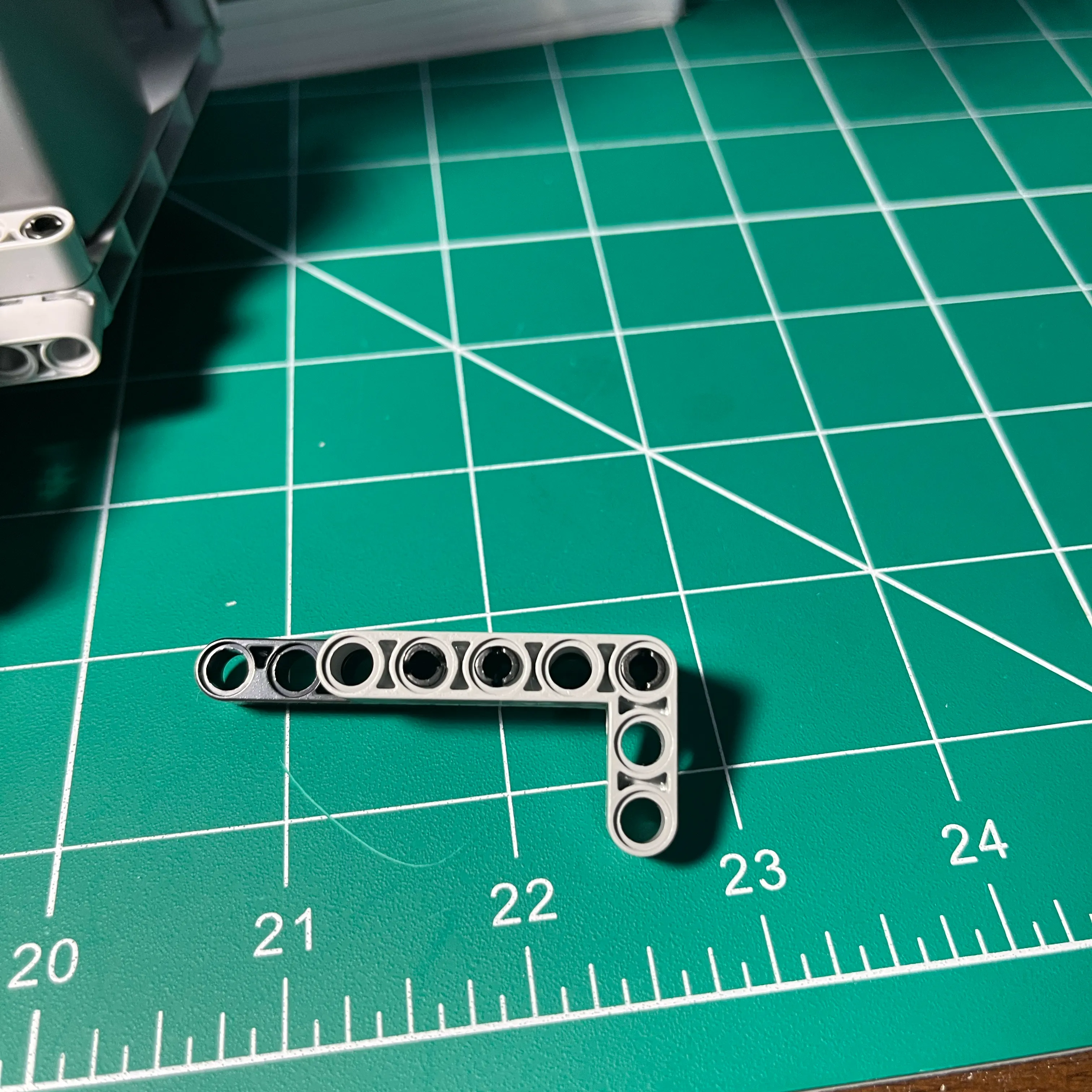
While prototyping the gear drive assembly, I stumbled upon the idea of a pivoting gear assembly beam. I was trying to find a way of arranging the gears on rigid beams, and I couldn’t get the gears to mesh with every combination I tried.
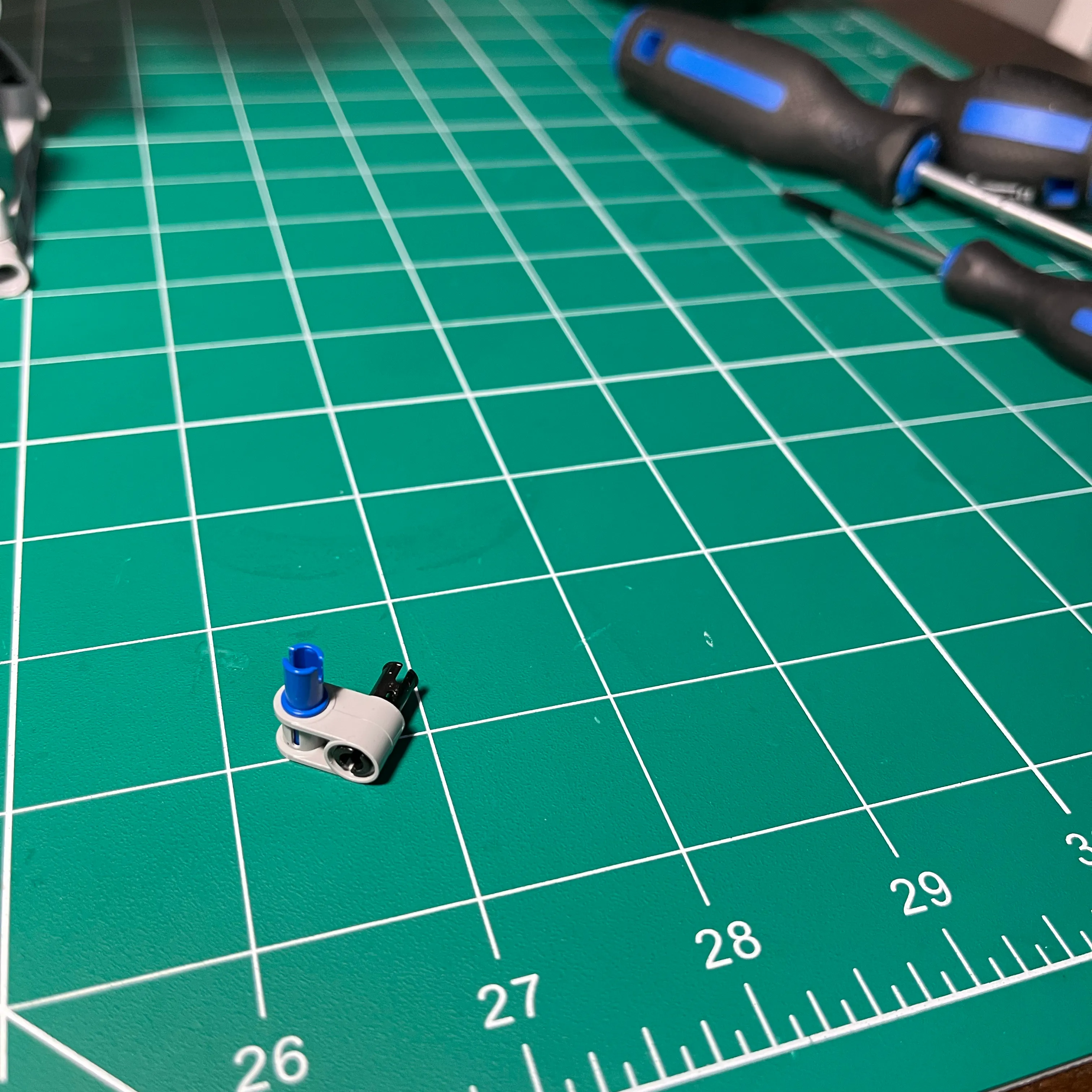
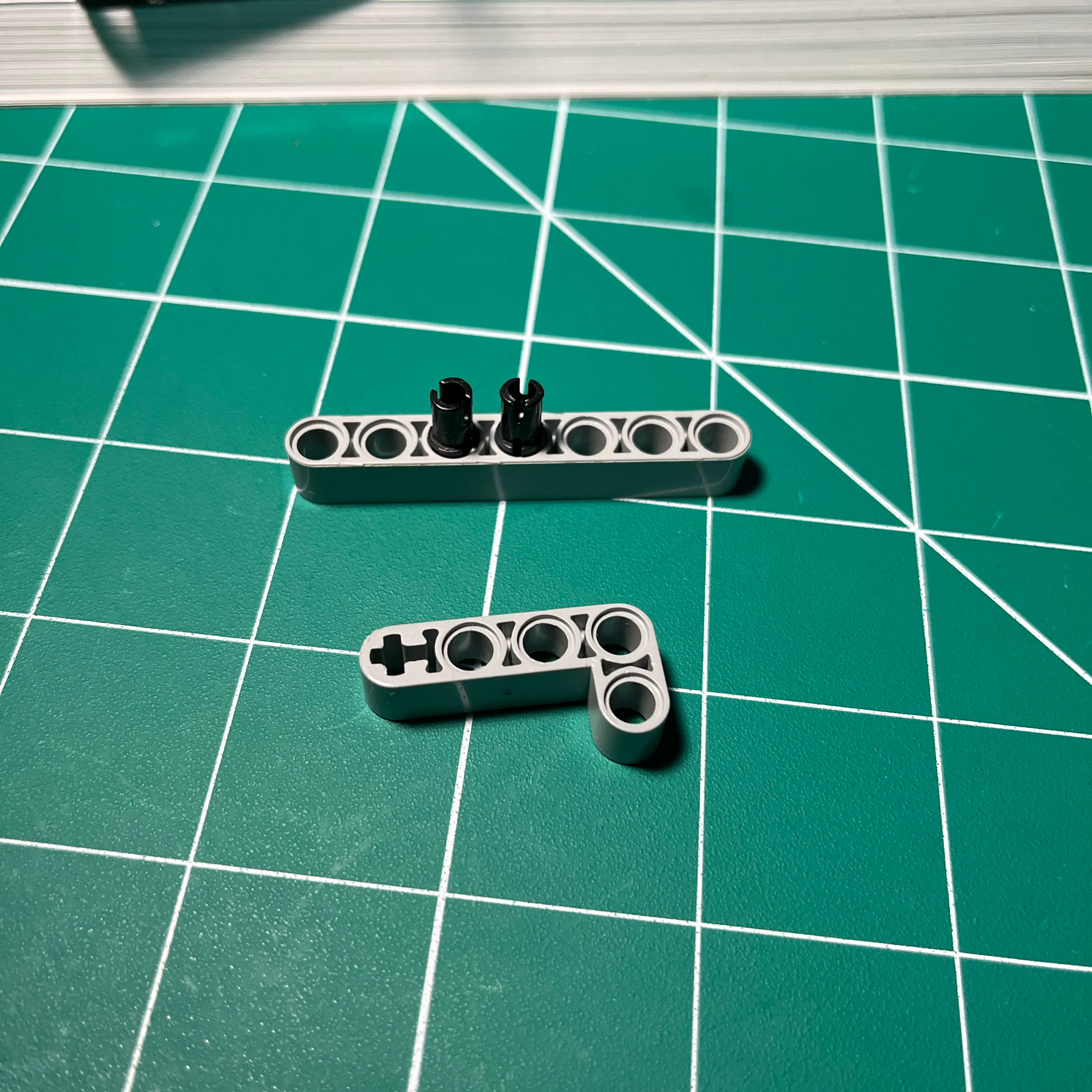
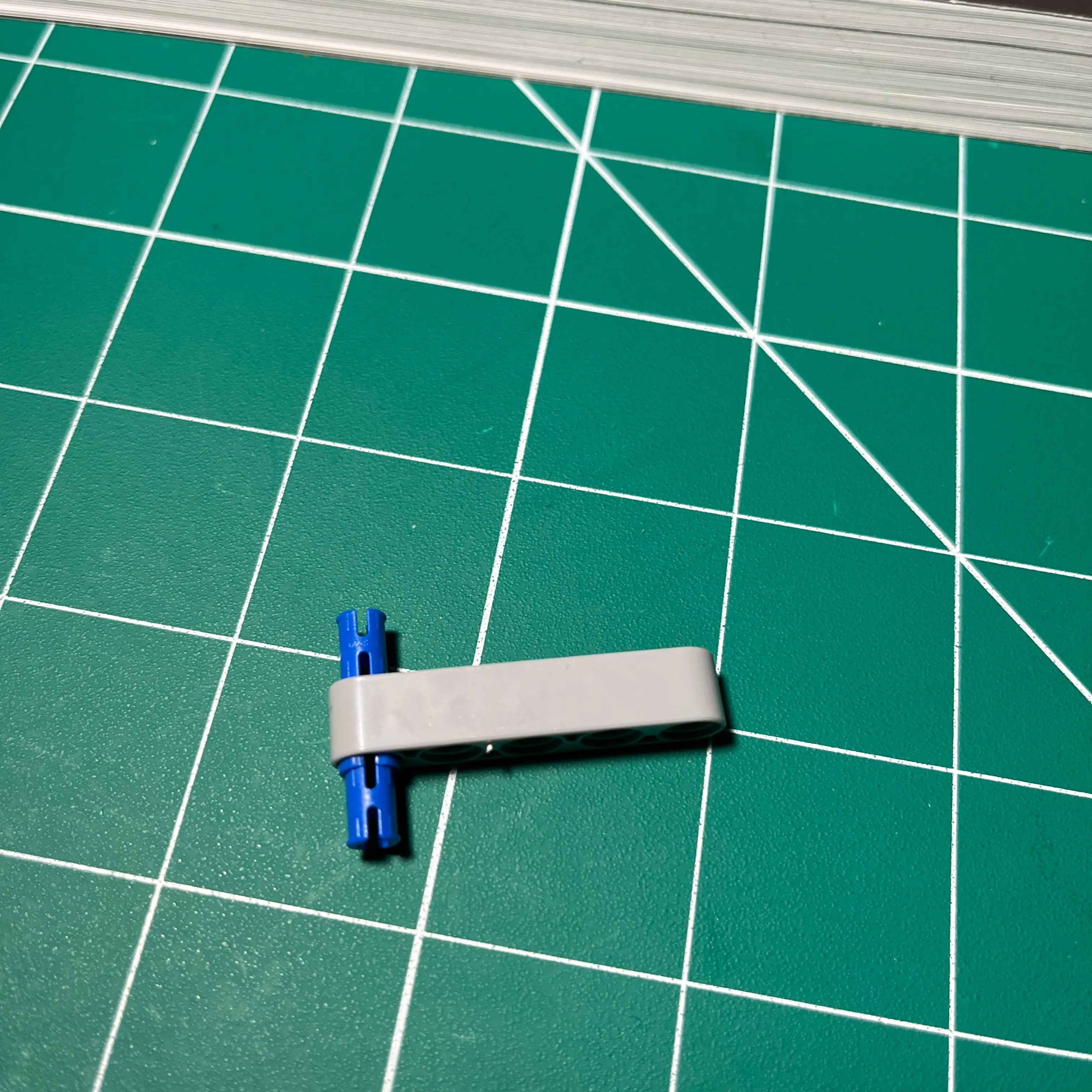
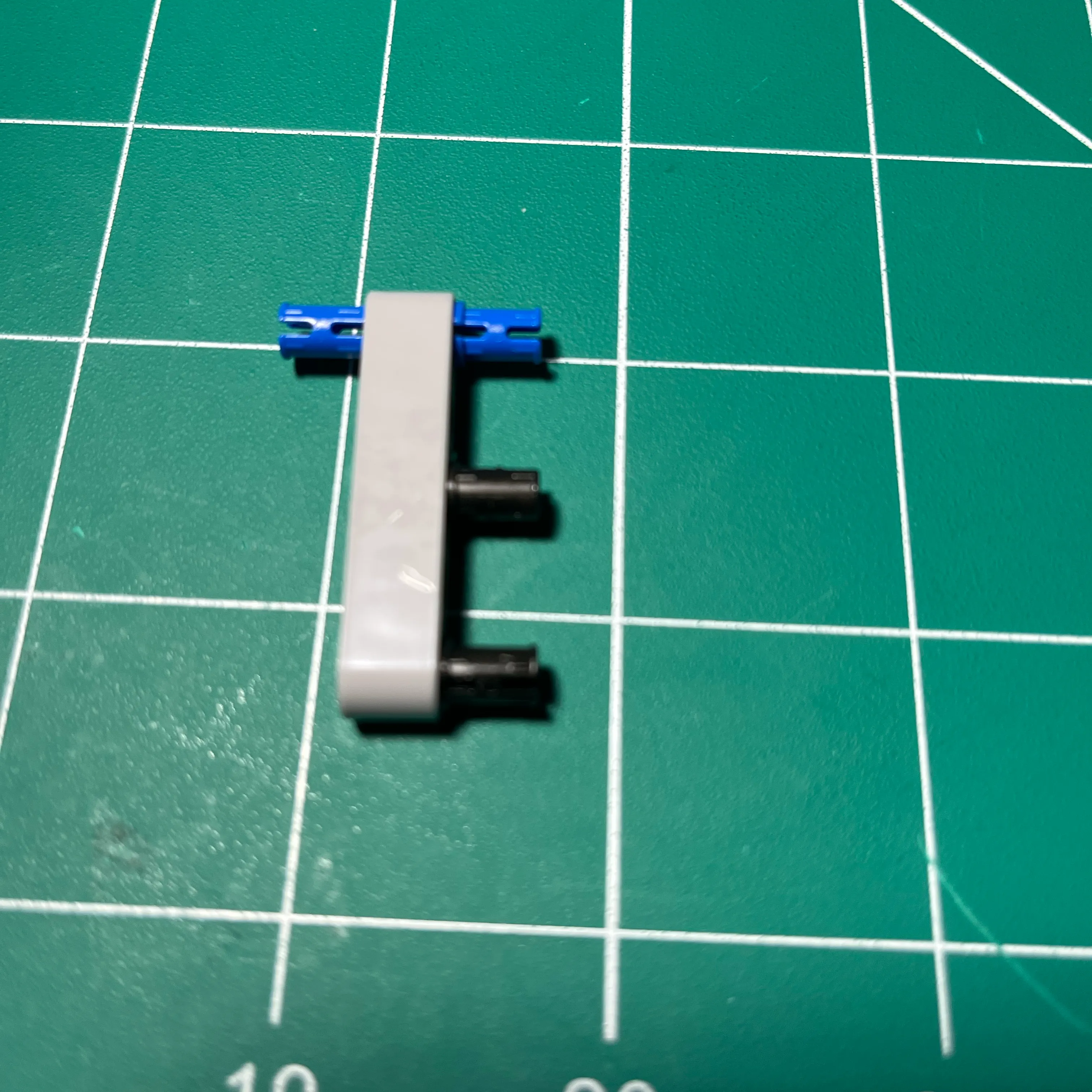
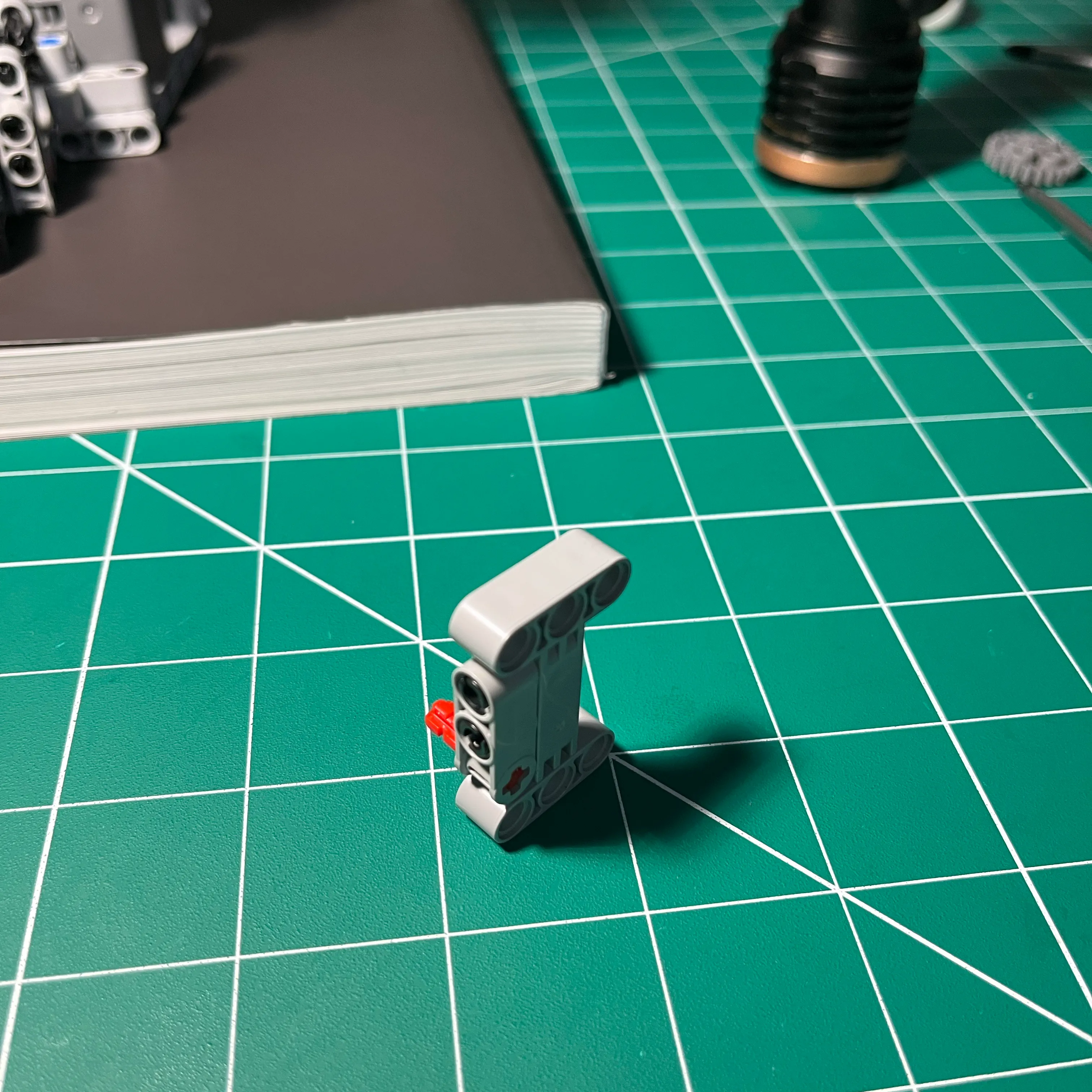
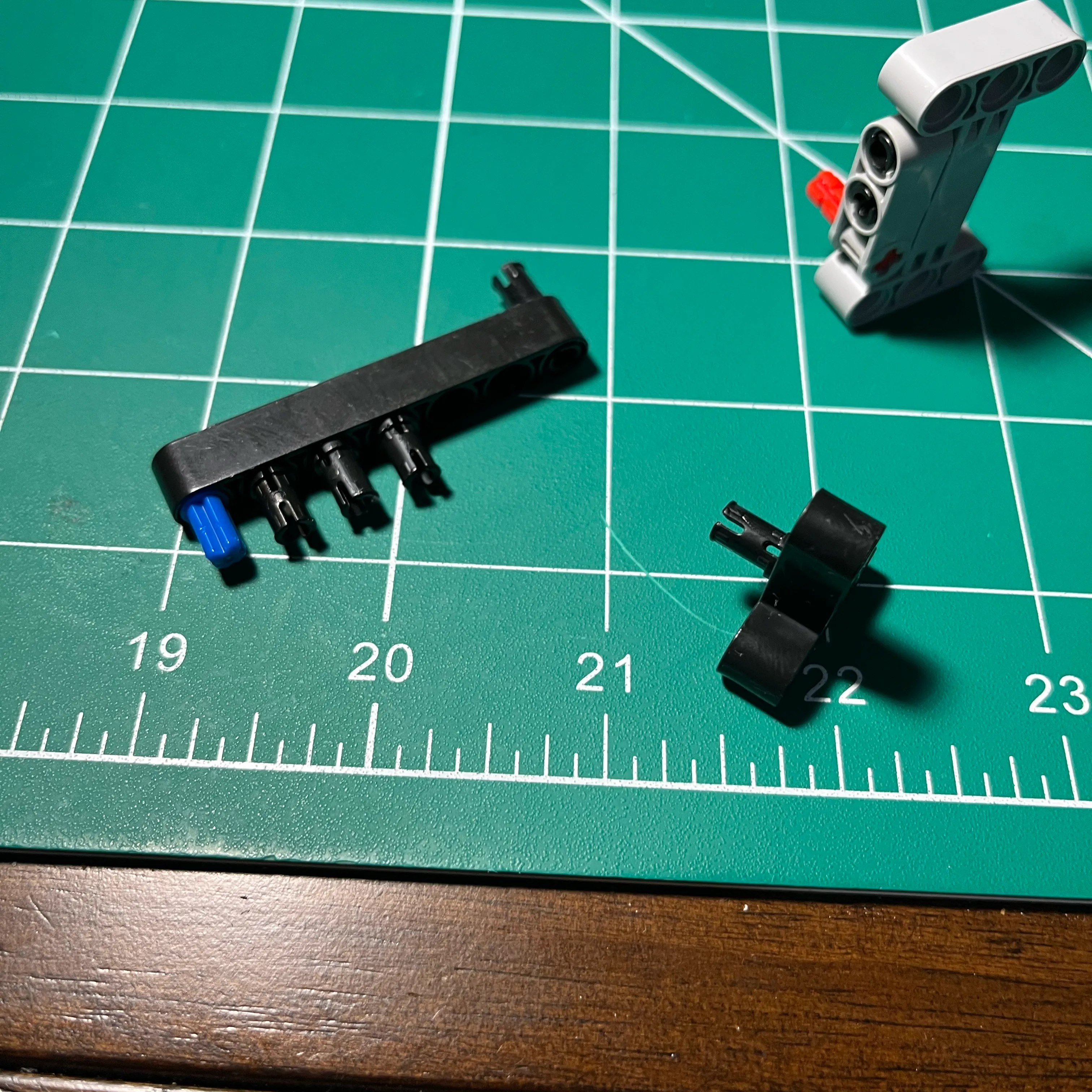
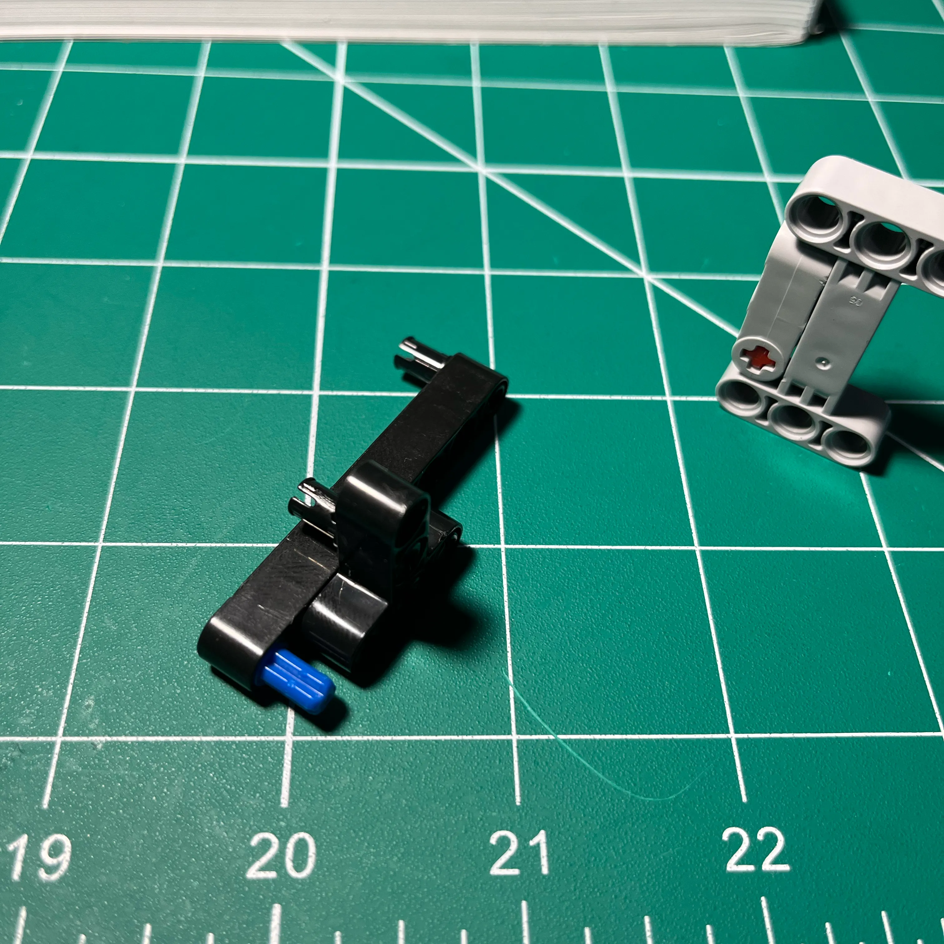
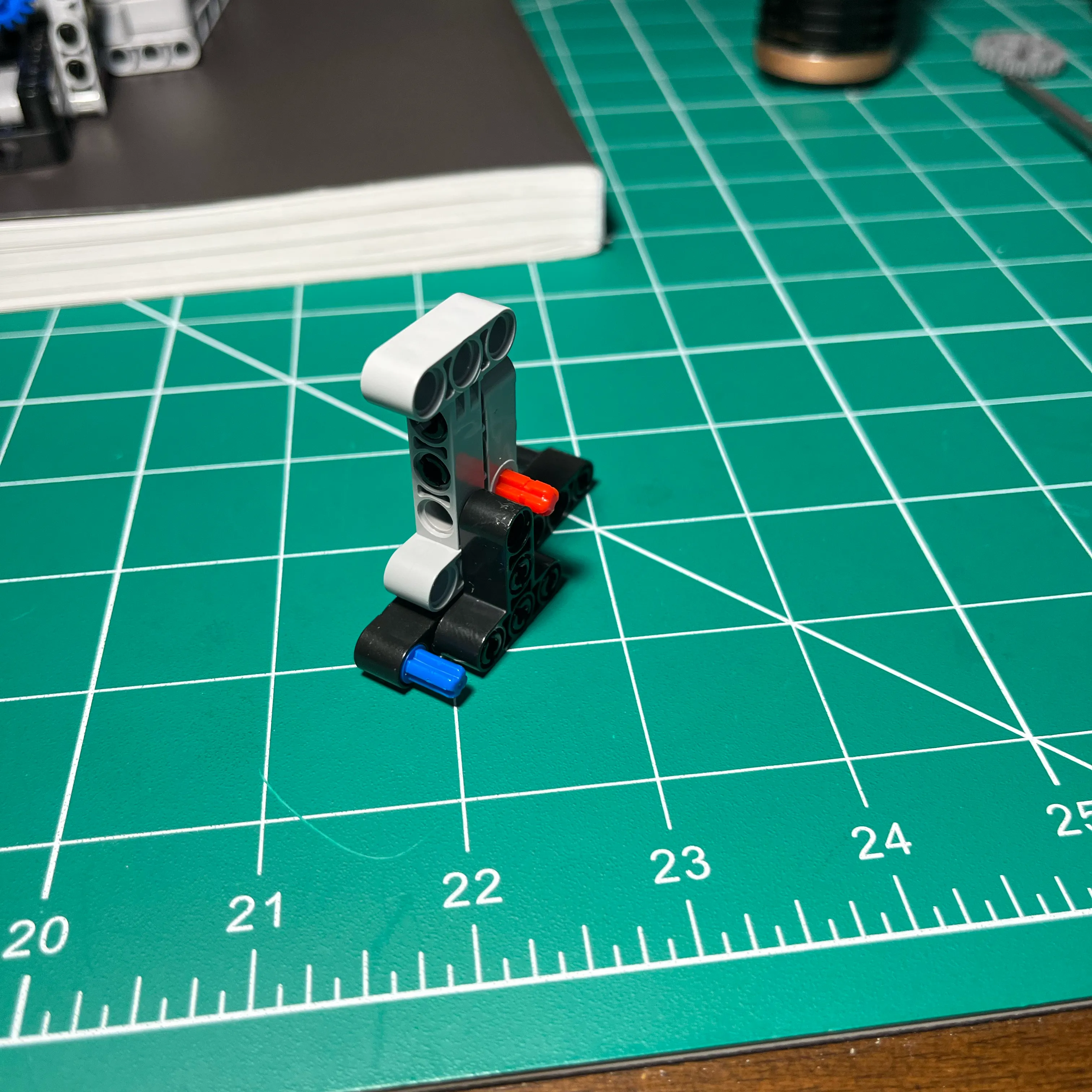
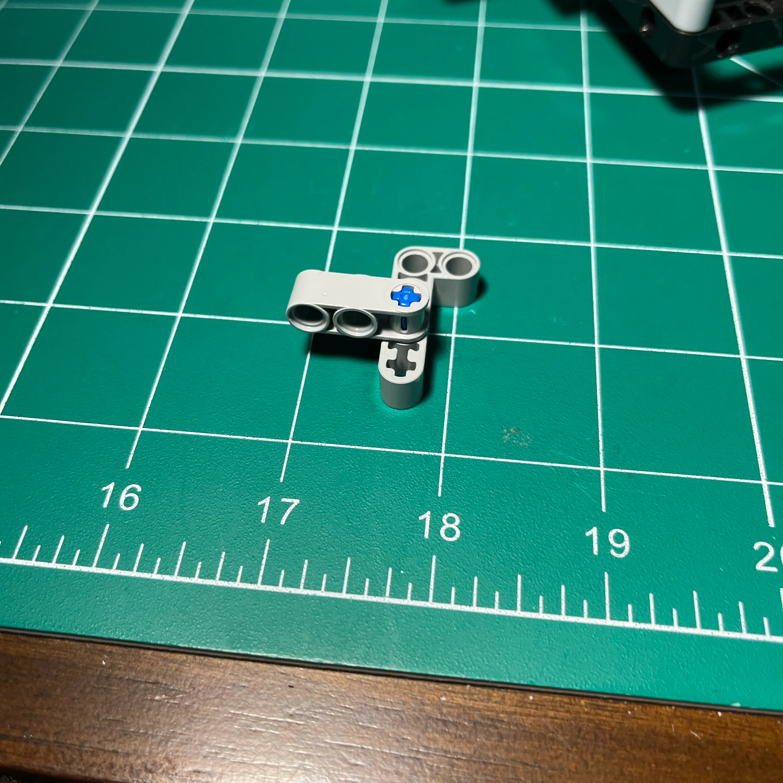
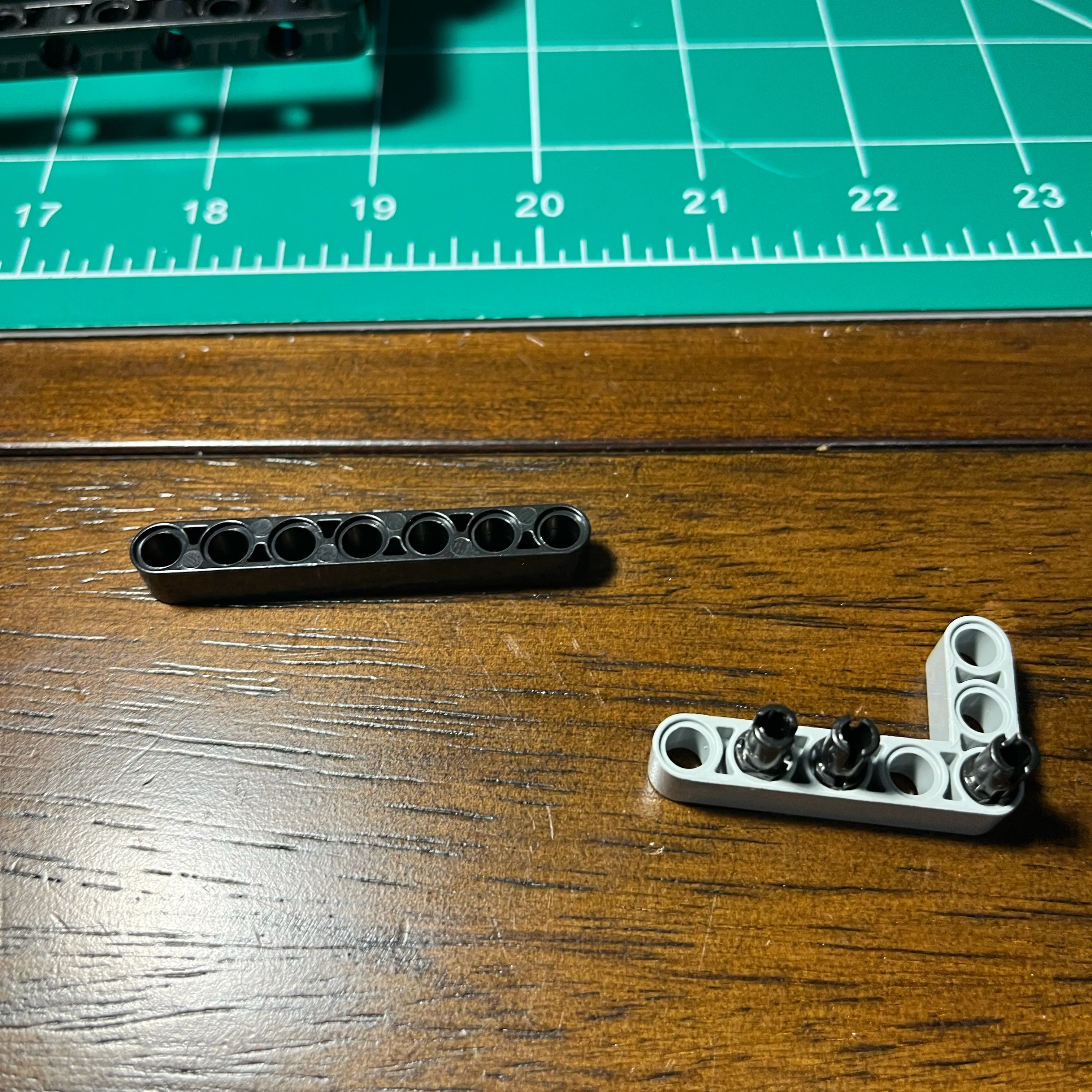
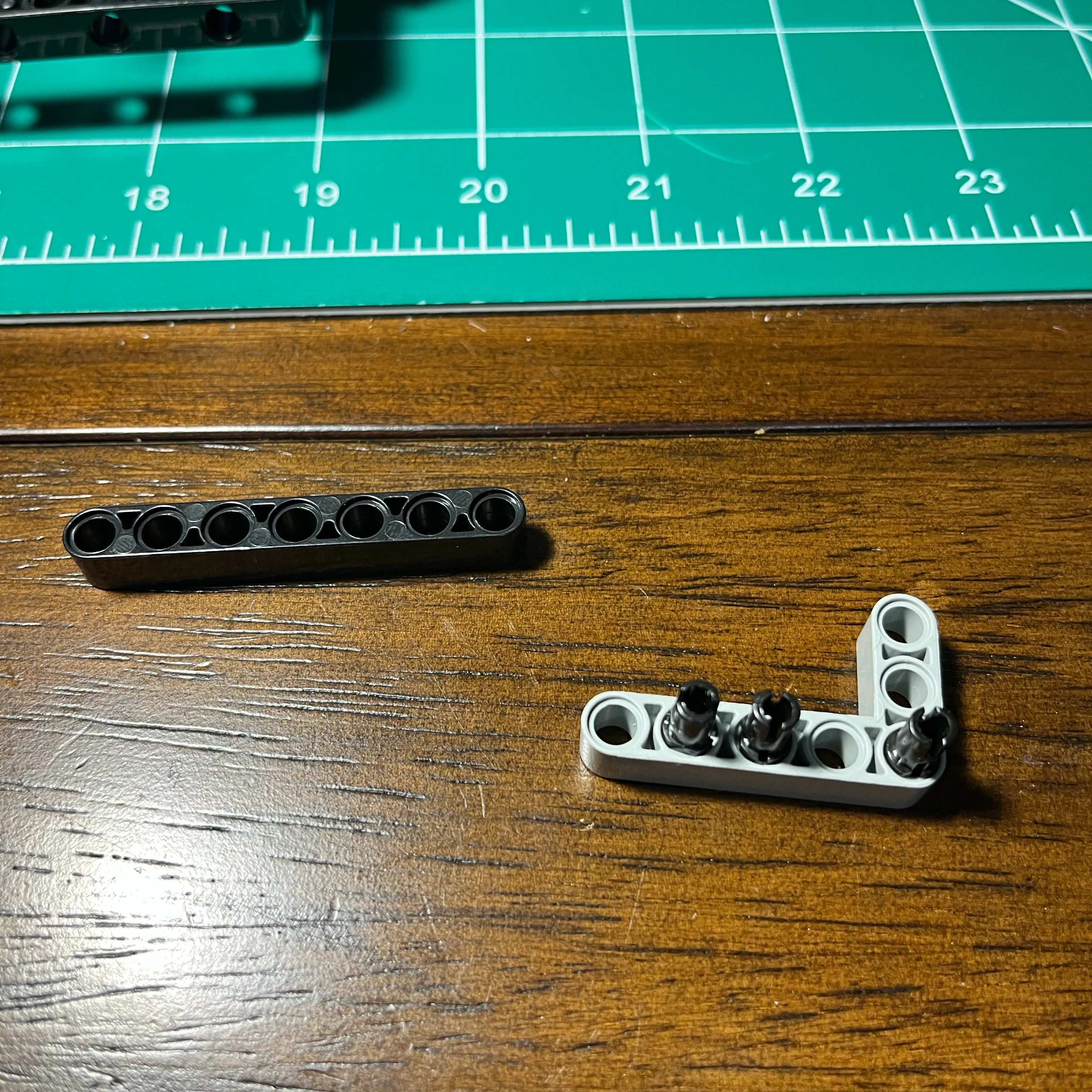
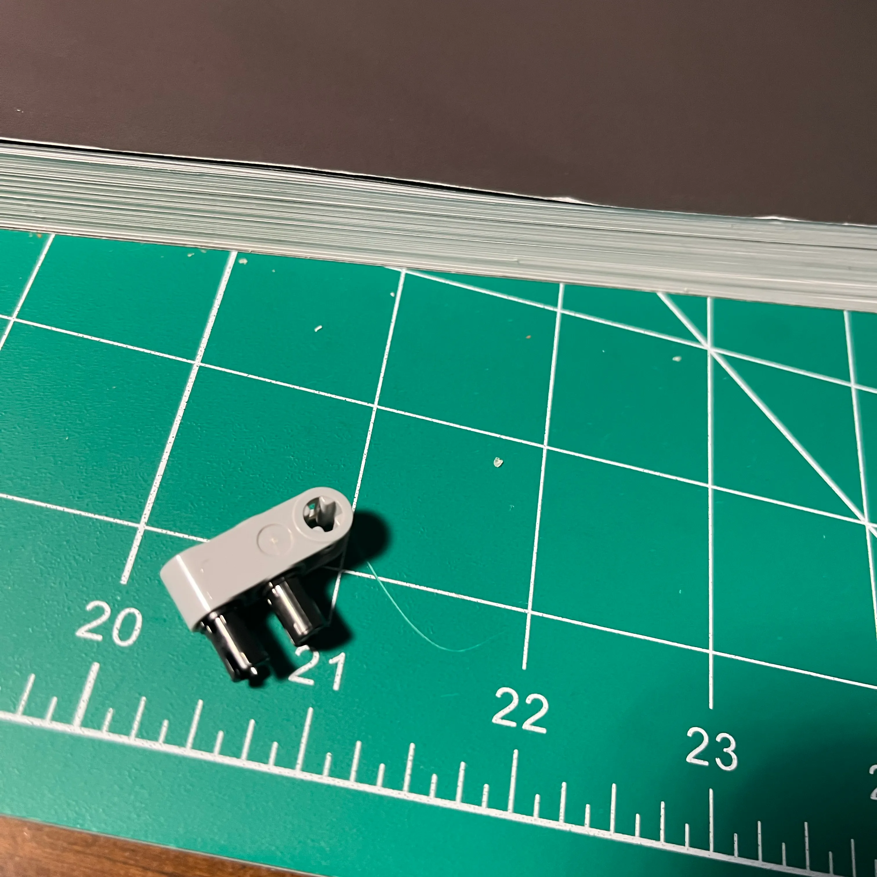
I discovered that I could get the gears to all mesh and rotate the cams on a single beam, but only if the beam was angled slightly. I had been playing around with these keyed pins for quick mockup when I wasn’t sure exactly where things needed to be placed. So I used that idea here.
I was moving the connector along the pin until it lined up with a structural connection point. Luck would have it that the required distance aligned perfectly with the right-hand wall of the engine block. That distance created enough tension to keep the gears meshed!
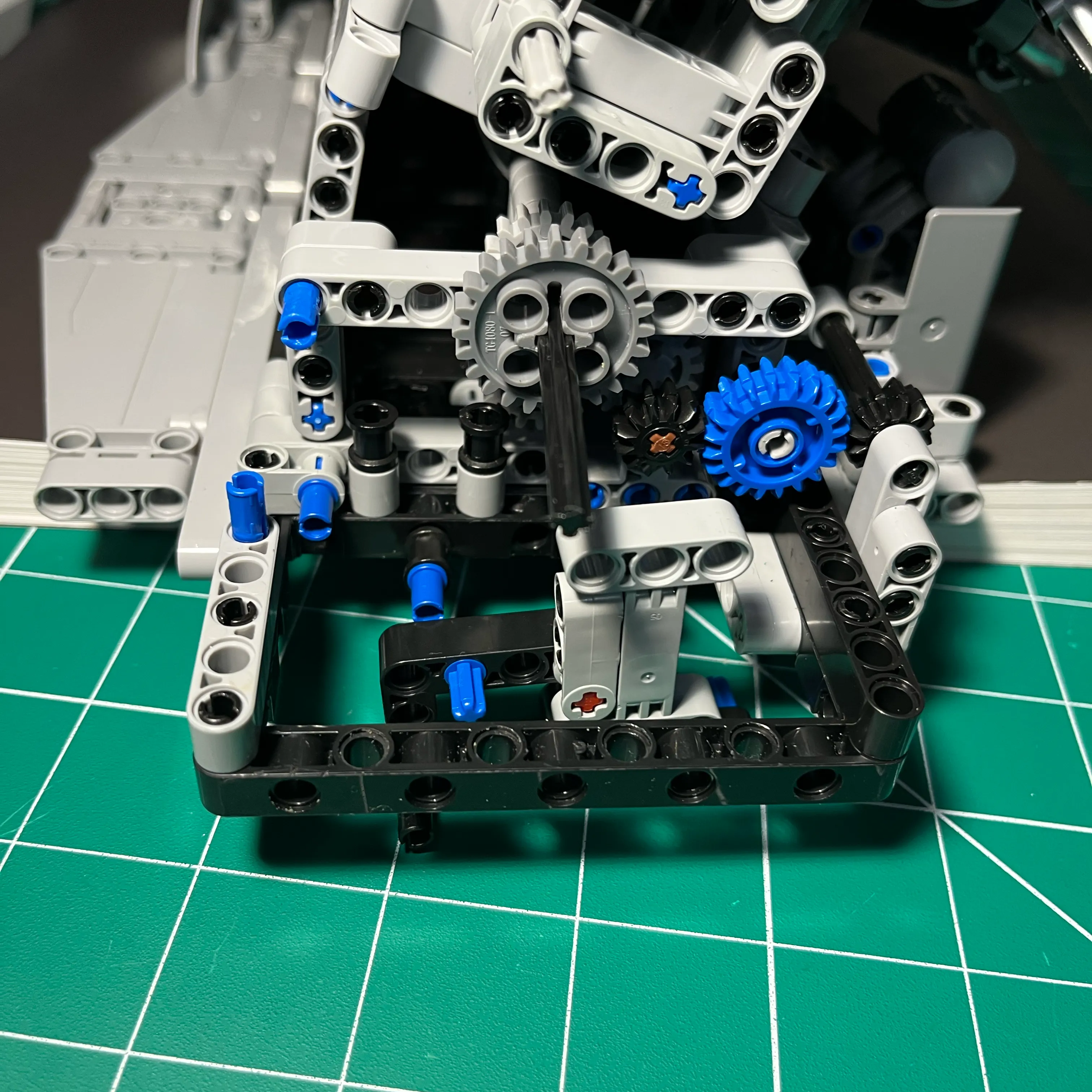
Cam Drive Gears Assembly Tensioner Support Brace
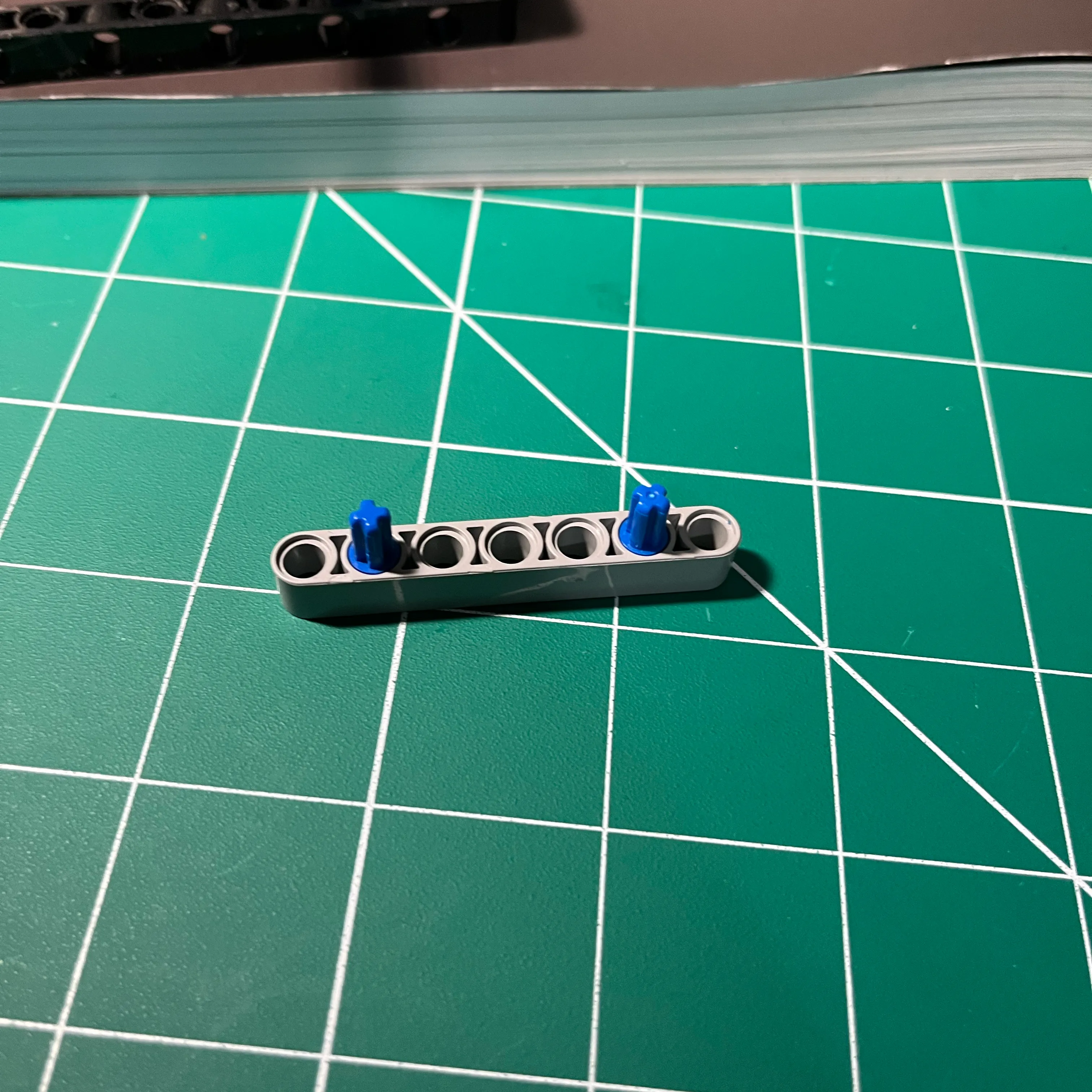
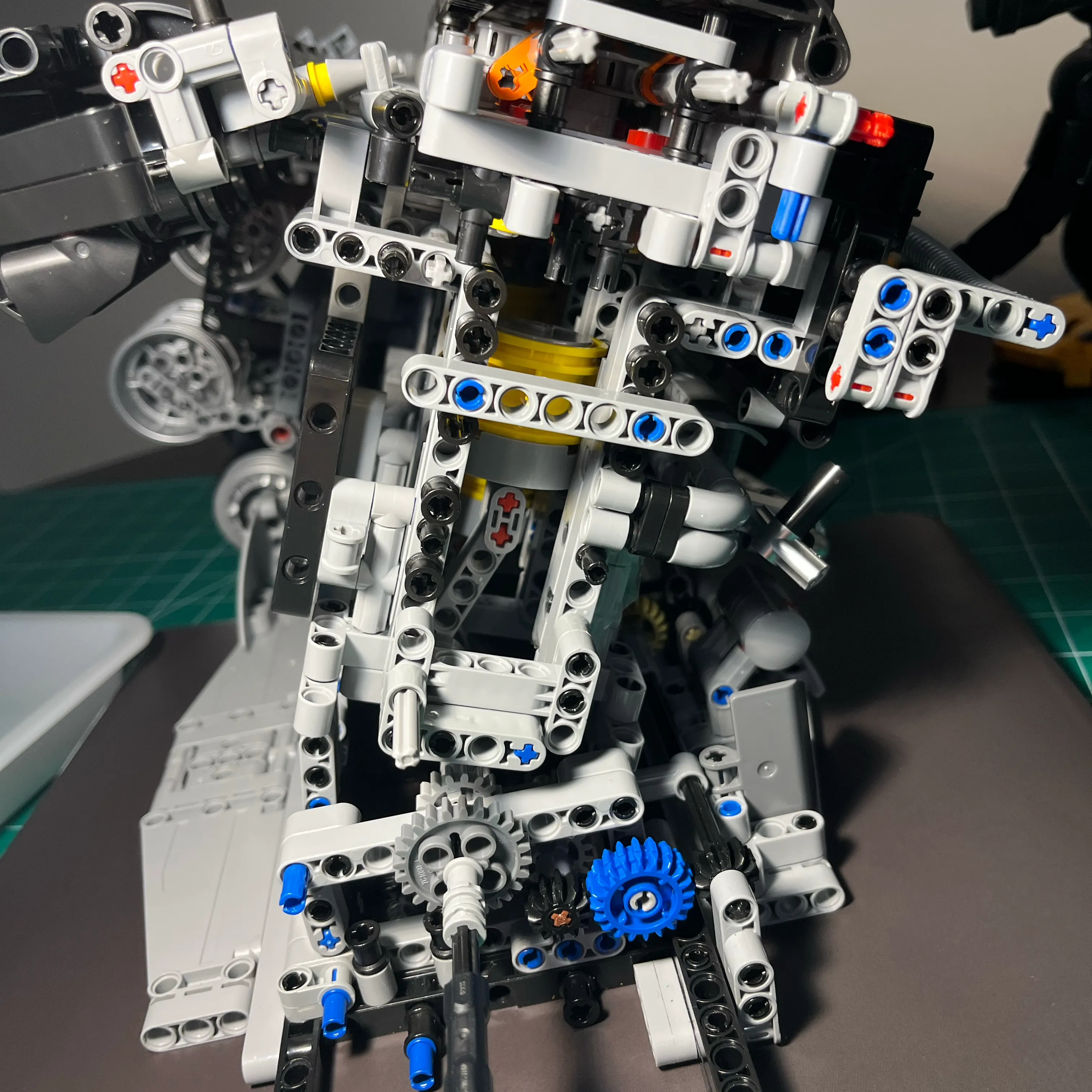
This brace acts as the anchor point for the tensioning lever. In a system without a chain, “tension” really refers to the pressure applied to keep the gear teeth tightly meshed together.
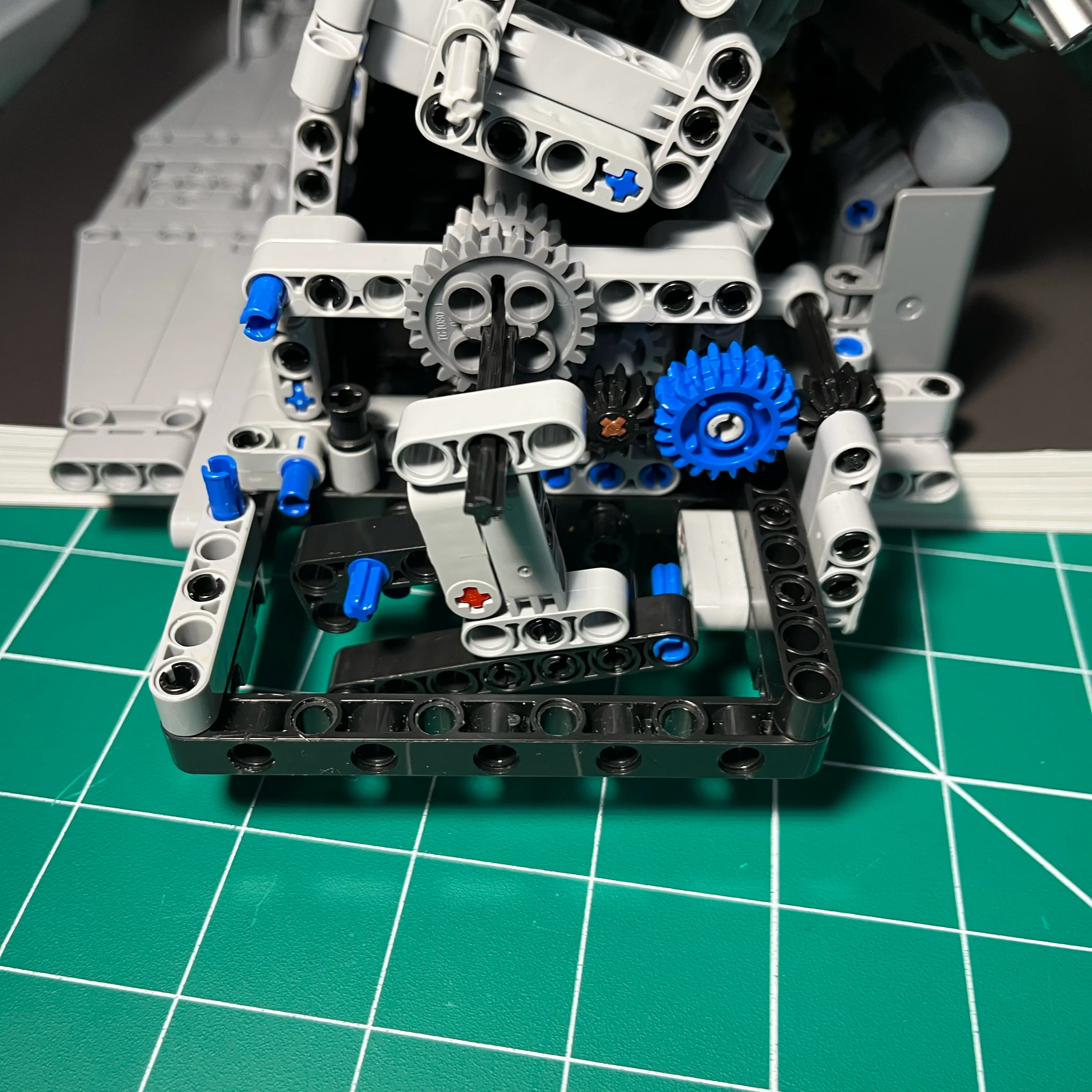
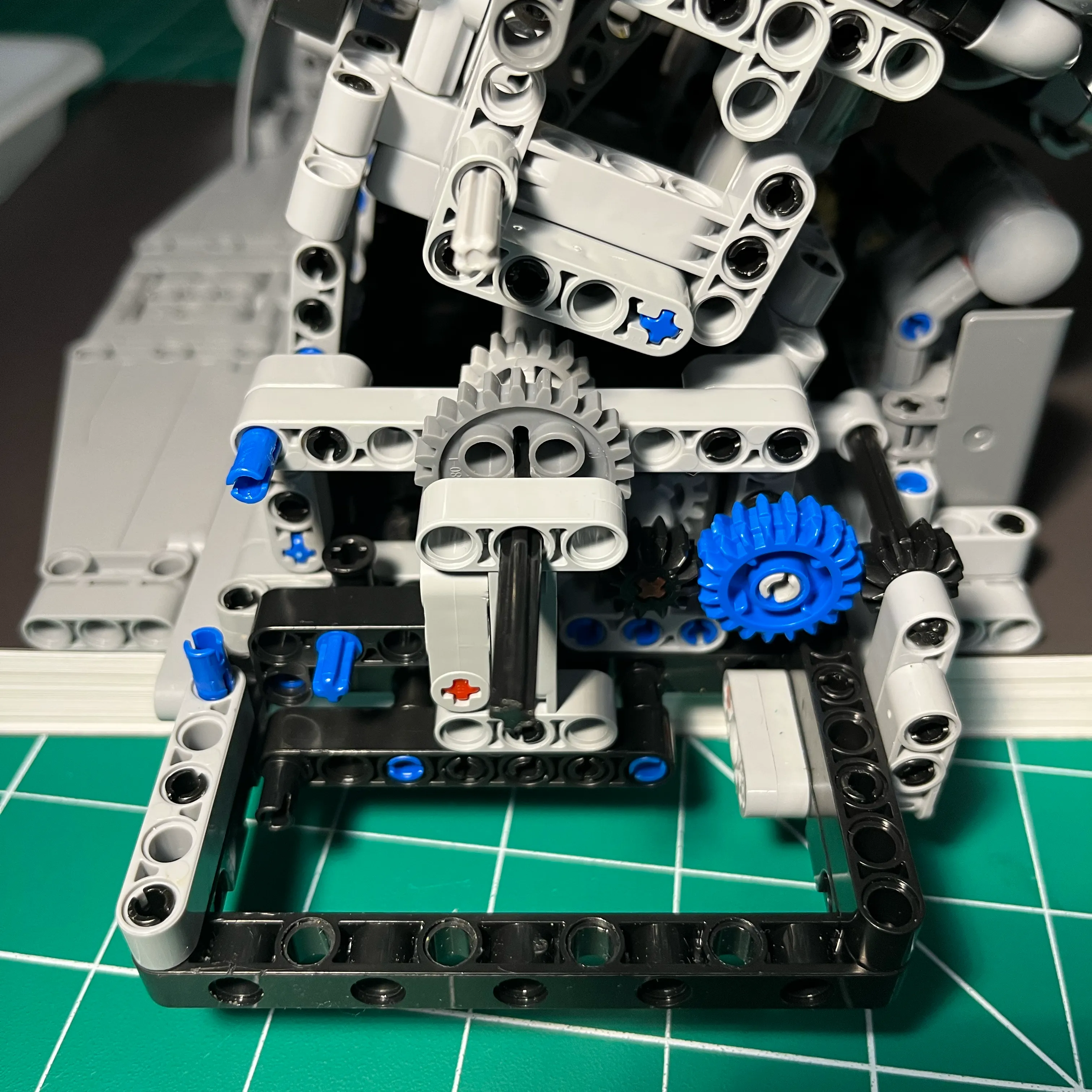
Building the Three-Gear Cam Timing Sub-Assembly
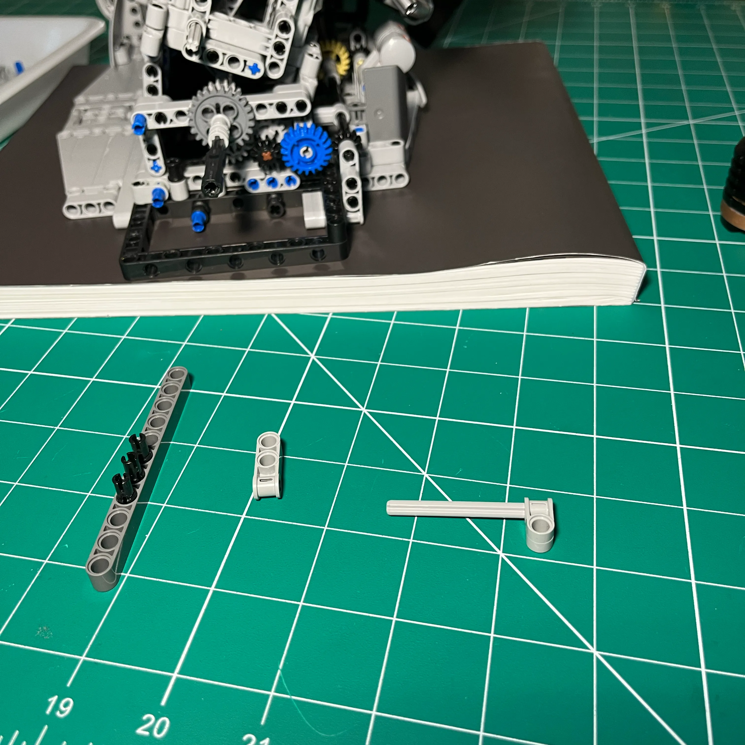
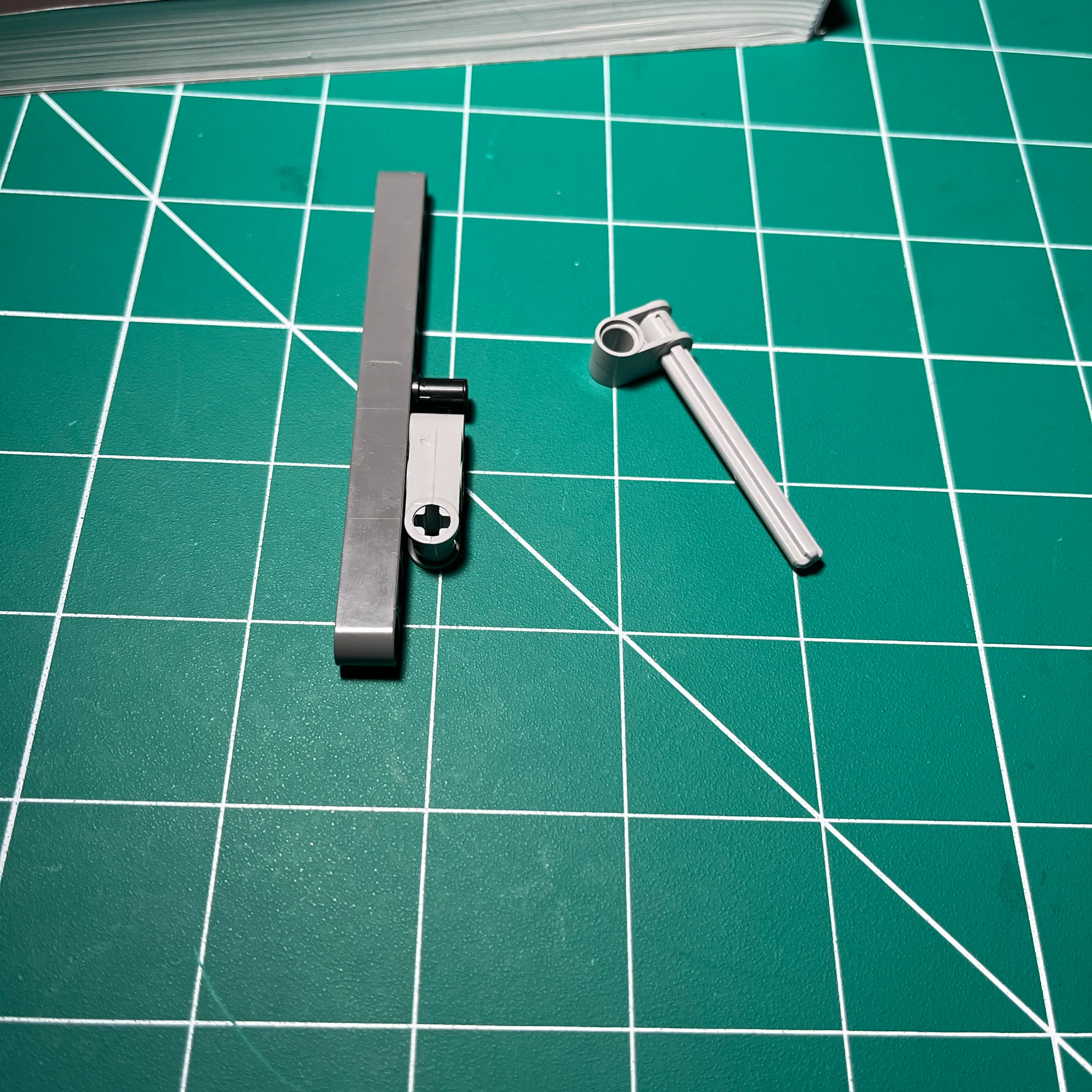
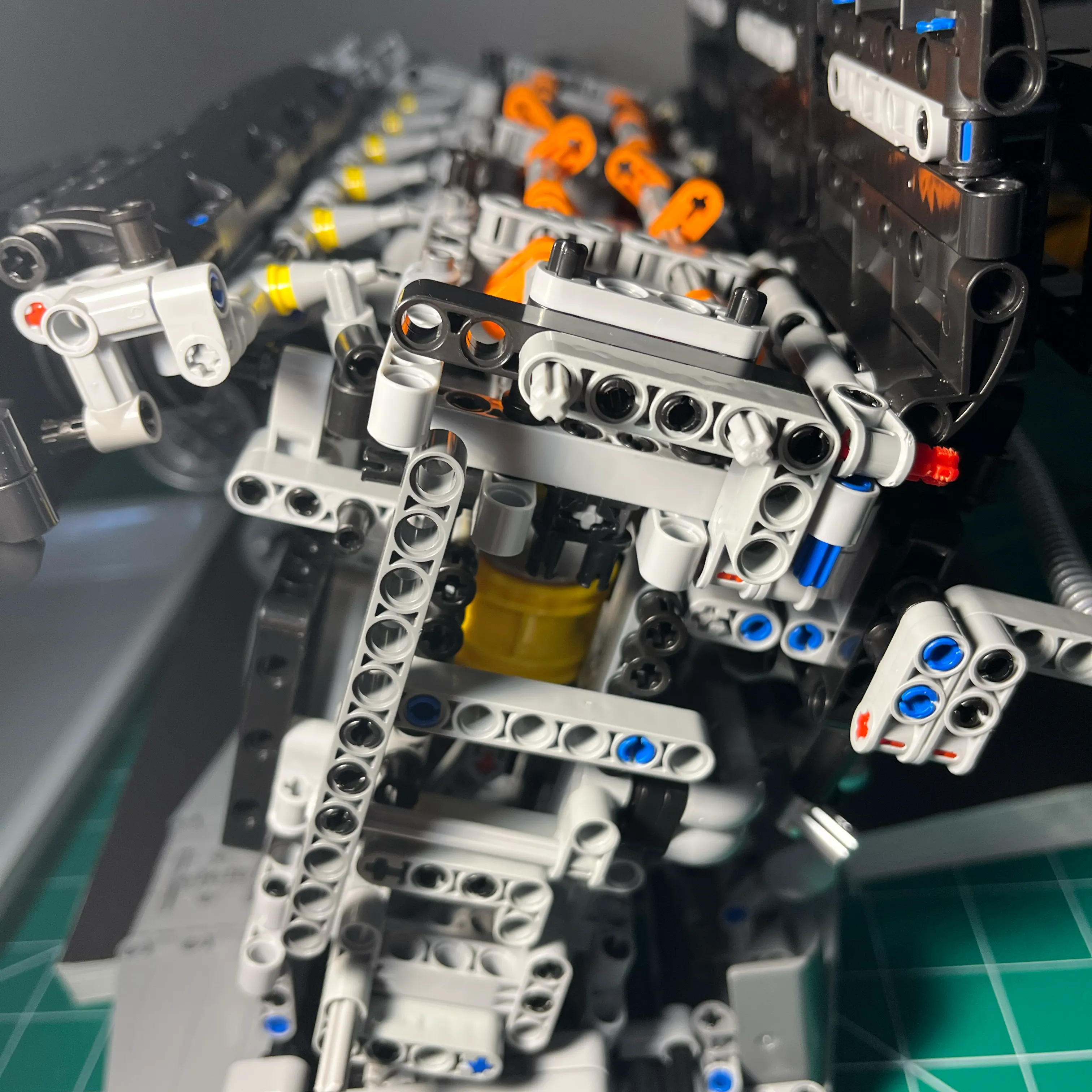
I like the simplicity and practicality of this design. I didn’t “design” this per se. Instead, it evolved during mockup having the beam connected to the cross brace by a single pin, and I happened to notice that with the gears installed I could get the gears into alignment by simply rotating the beam by hand. The idea of the using an axel came about when I considered how I could get the 3 gear assembly to stay where I had placed it by hand.
Crank Gear Support Assembly
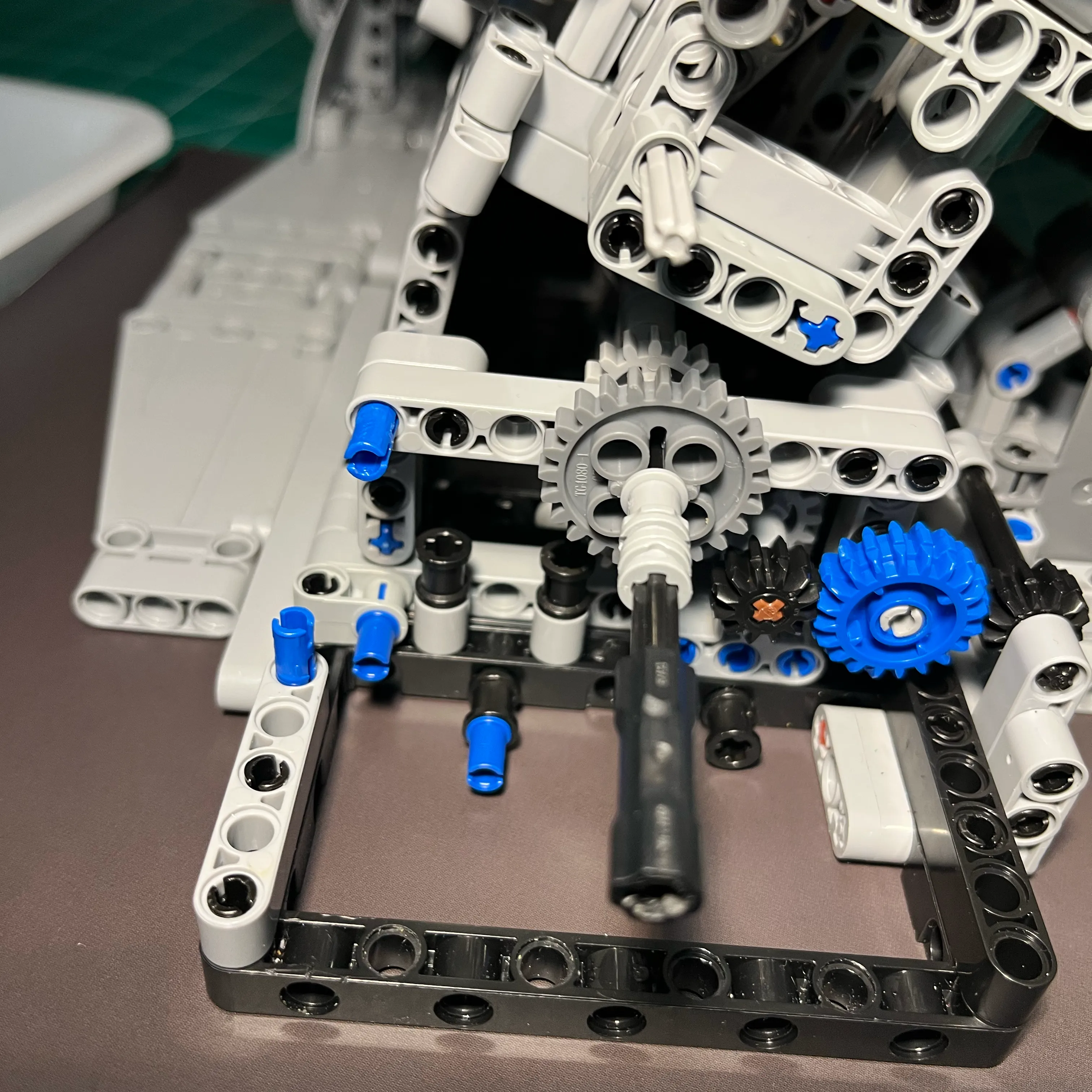
This design came about by trial and error, using components I had and the constraints of the design of the NifeliZ L6 model engine. the right-side of the crank had the gears that drive one of the front accessories.
These 2 small gears are part of the system that is apparently supposed to be used when adding an electric motor. Those gears are not strong enough to turn the engine over, so I will not be installing an electric motor where the instructors indicate. With the reinforced gears at the rear of the engine, that’s where I’d put an electric motor. I’ve already used an electric drill to do this, so an electric motor would work there.

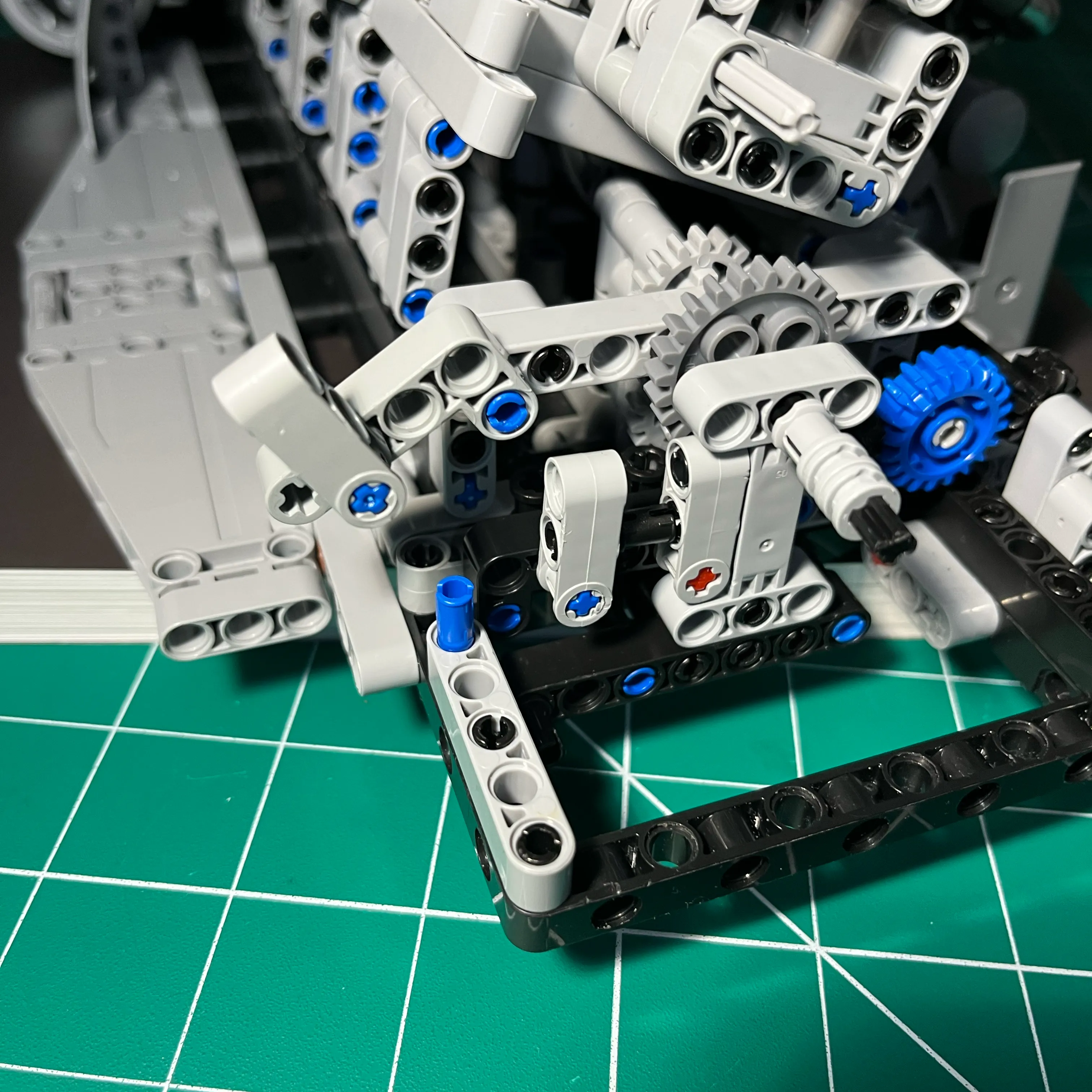
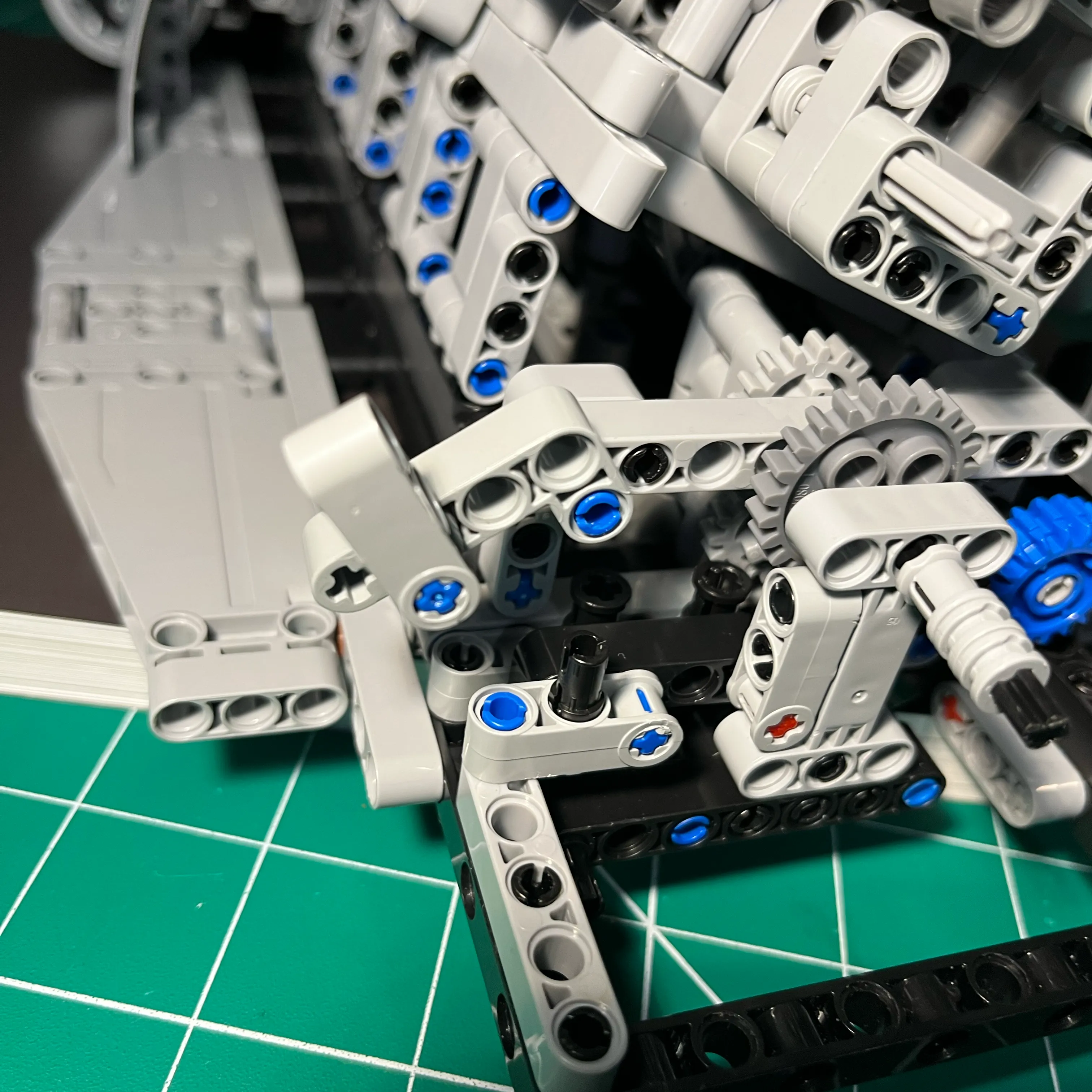
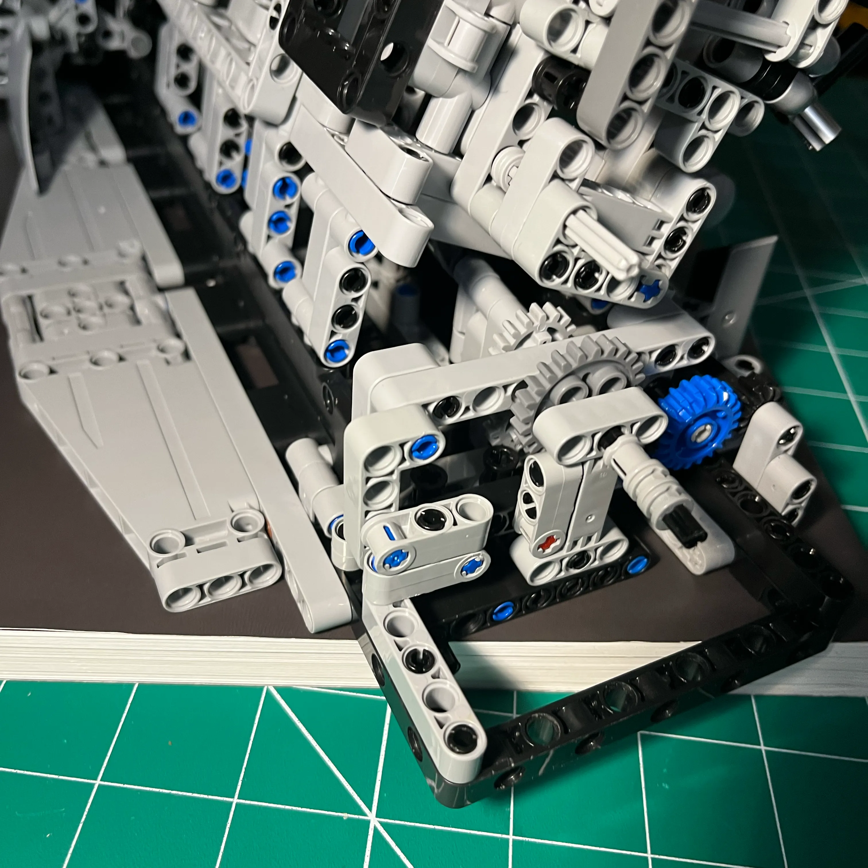
Cam Gears Install
The support brace behind the cam gears is floating, acting as a spacer to put the cam gears in vertical alignment with the other gears. I didn’t see a need to attach it to structure.
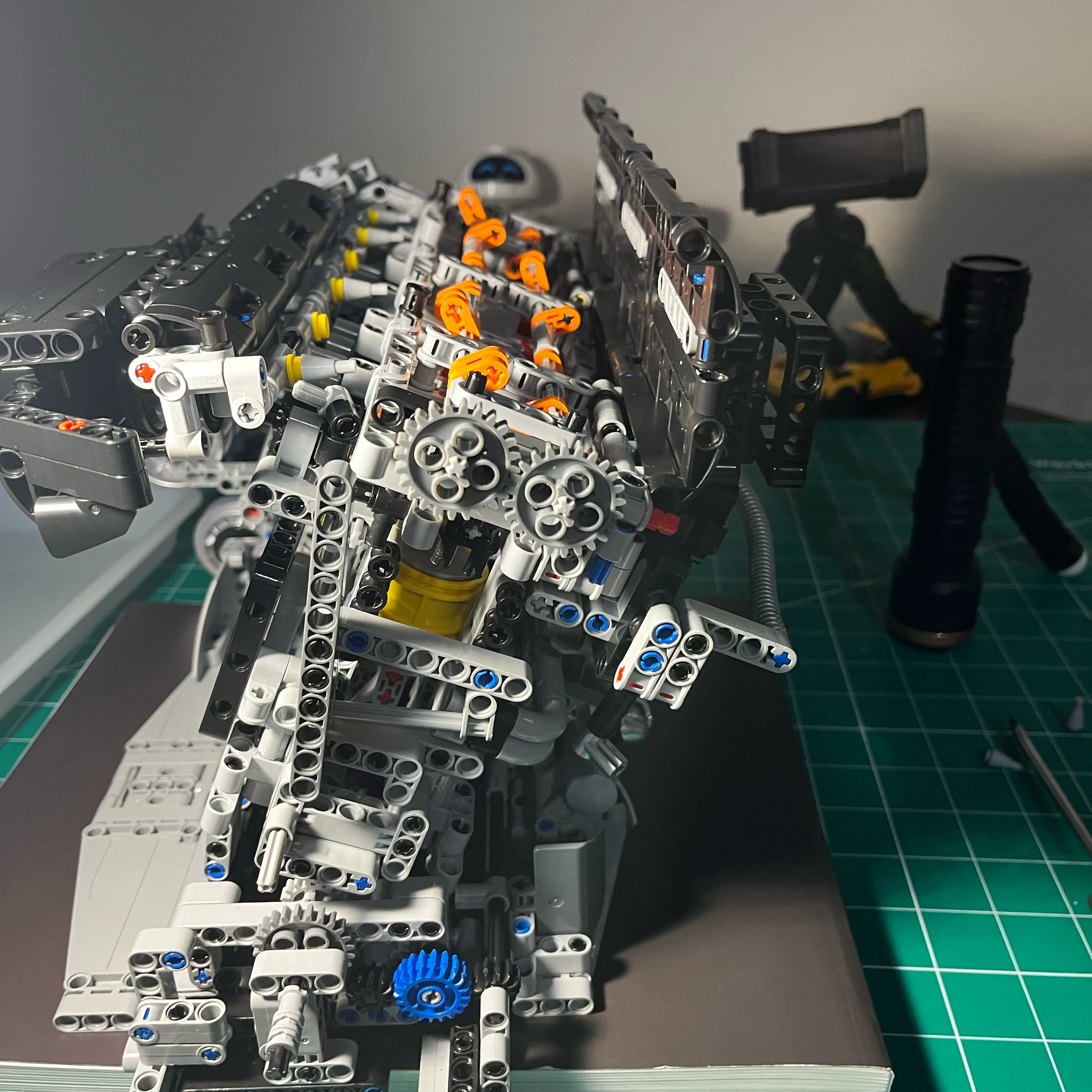
Cam Drive Gears Assembly - Install Gears
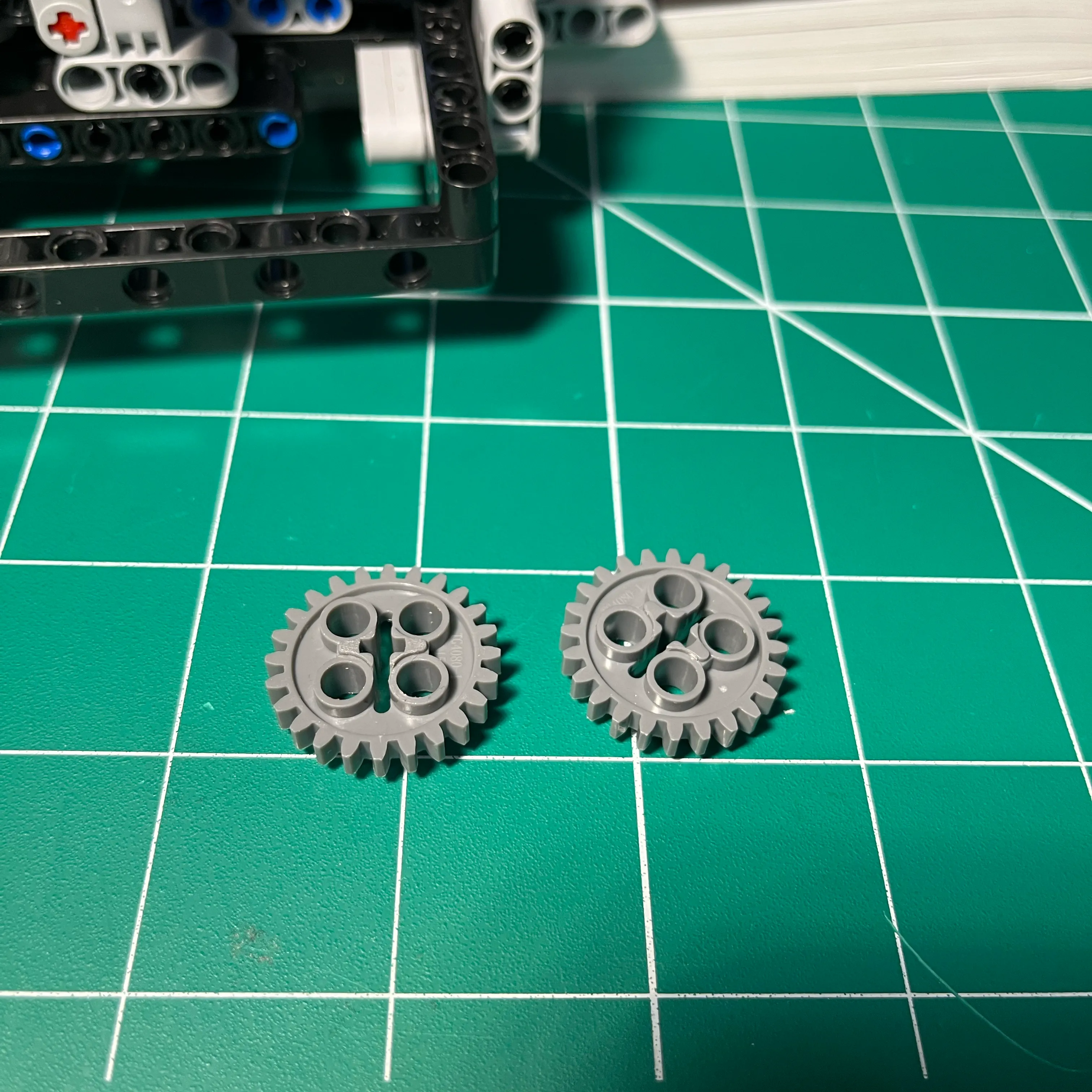
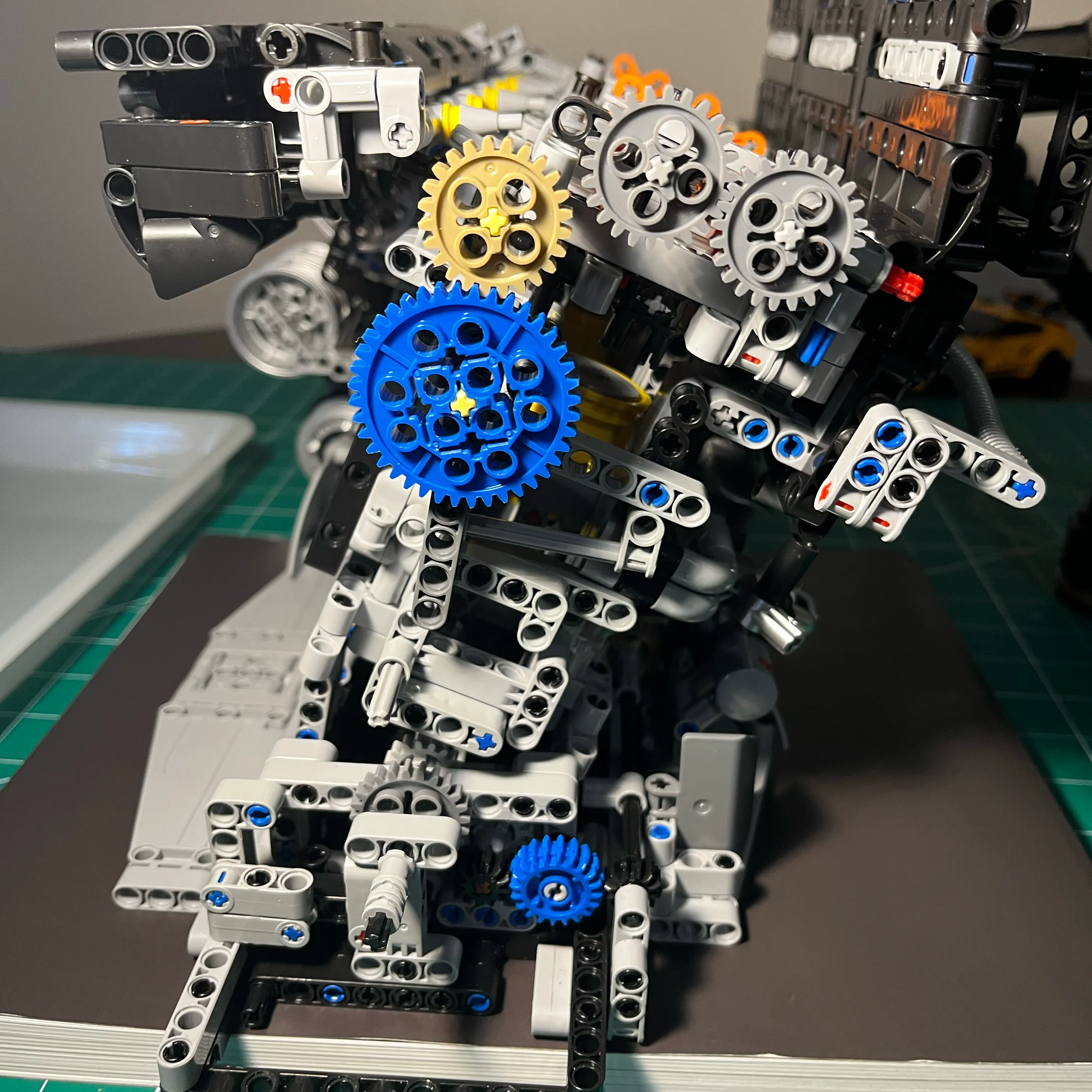
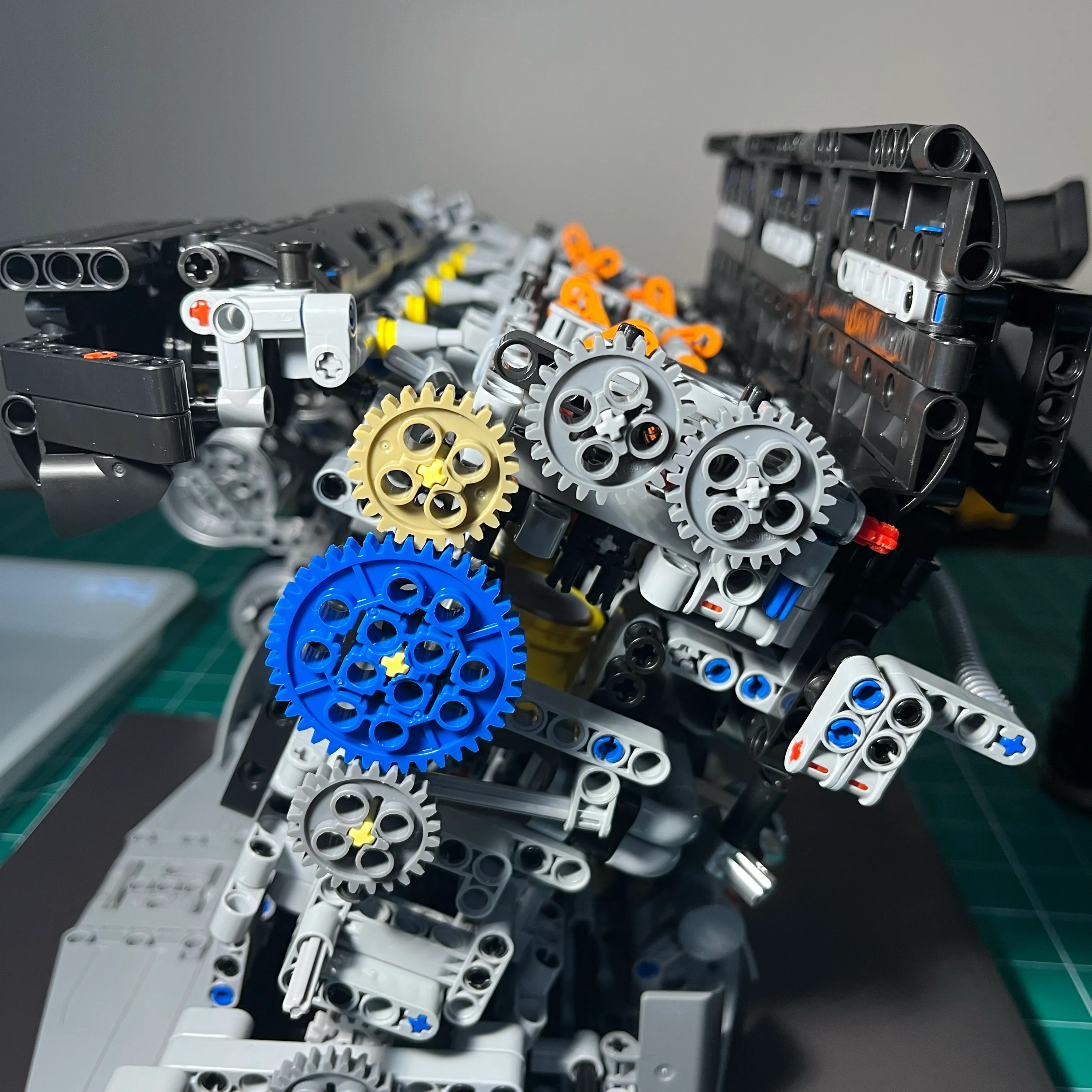
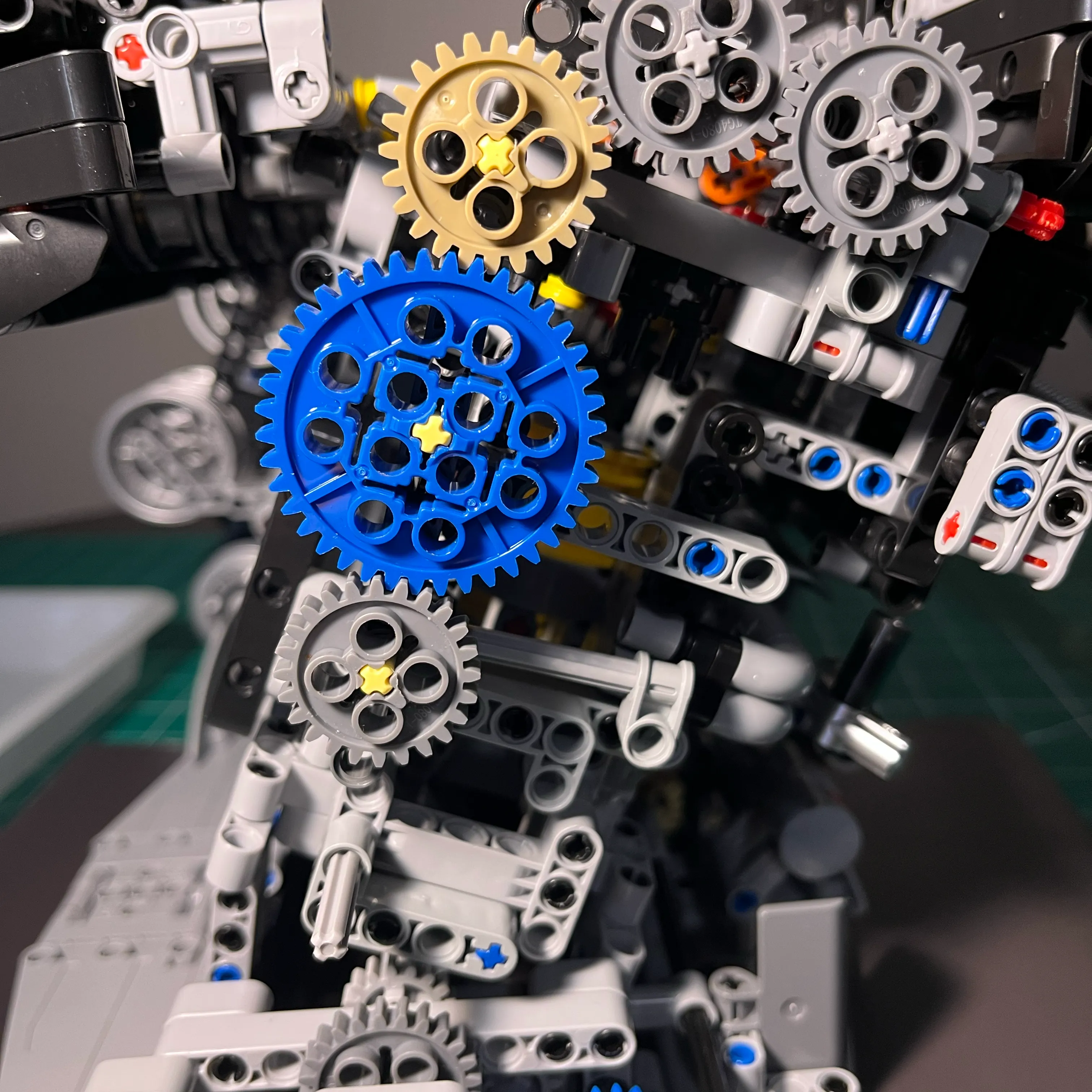
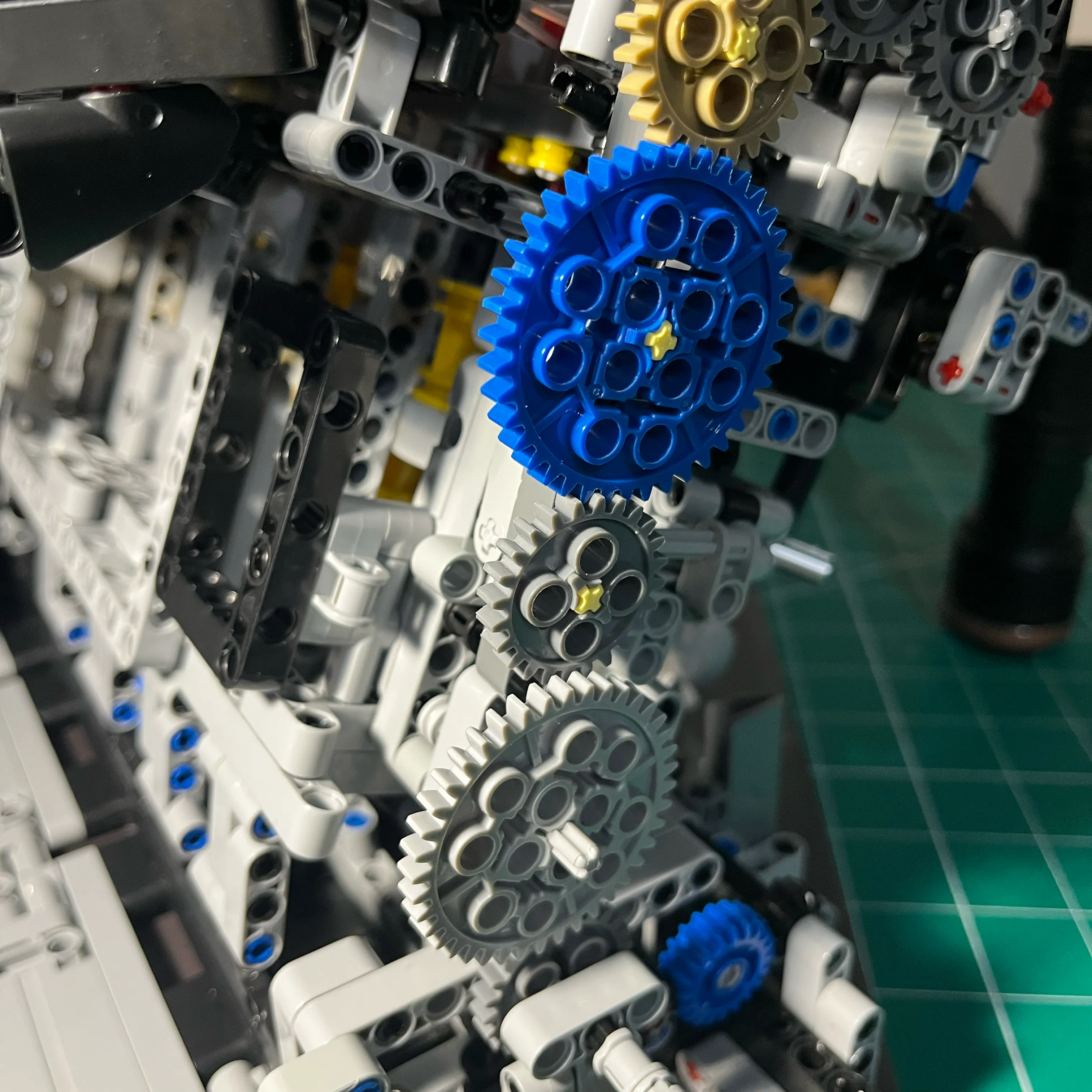
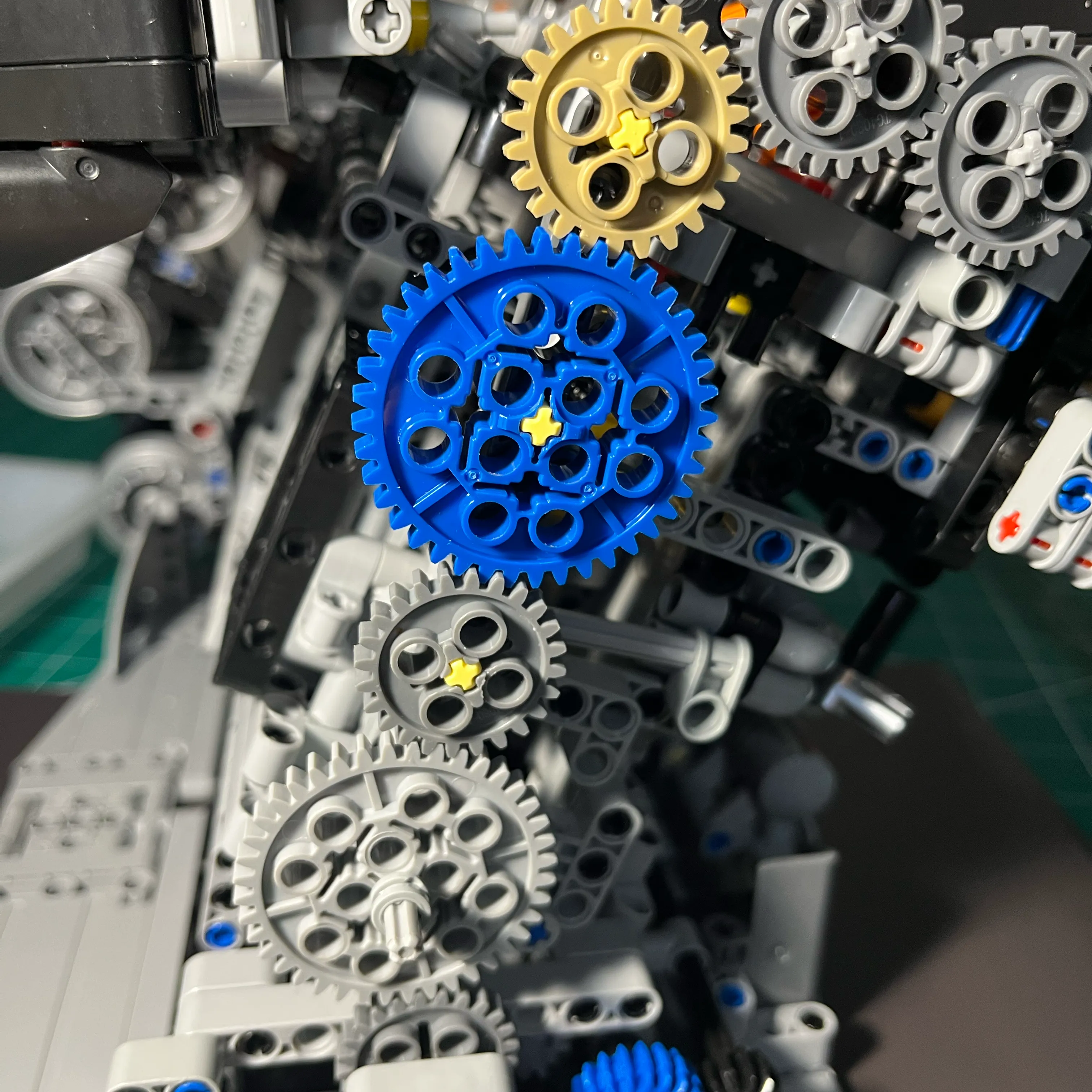
It’s satisfying to have those 3 gears all on the same beam. I did not concern myself with getting the correct 2:1 crank to cam gear ratios for proper 4-stoke engine timing. For my purposes, seeing the cams turn as the engine turns over is good enough.
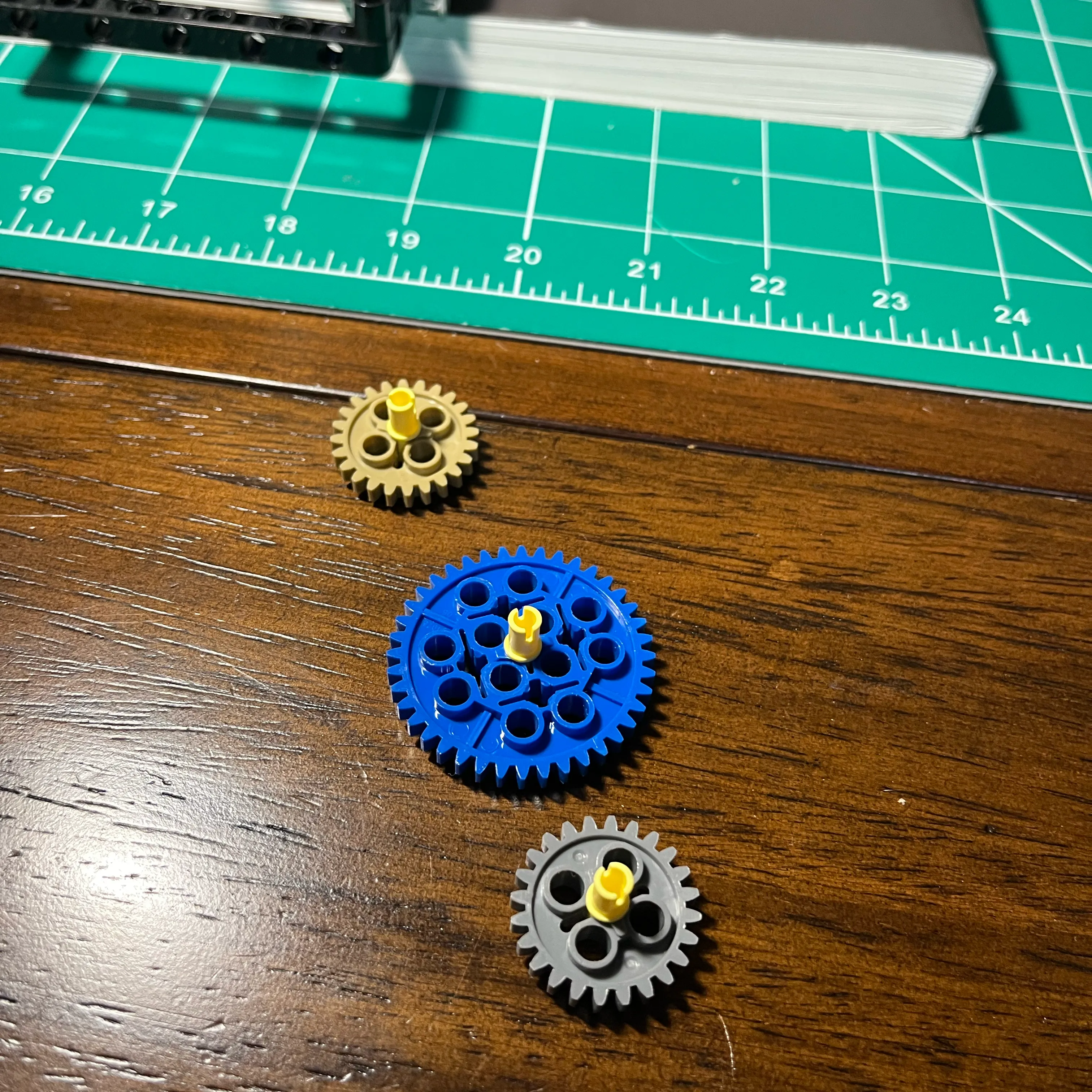
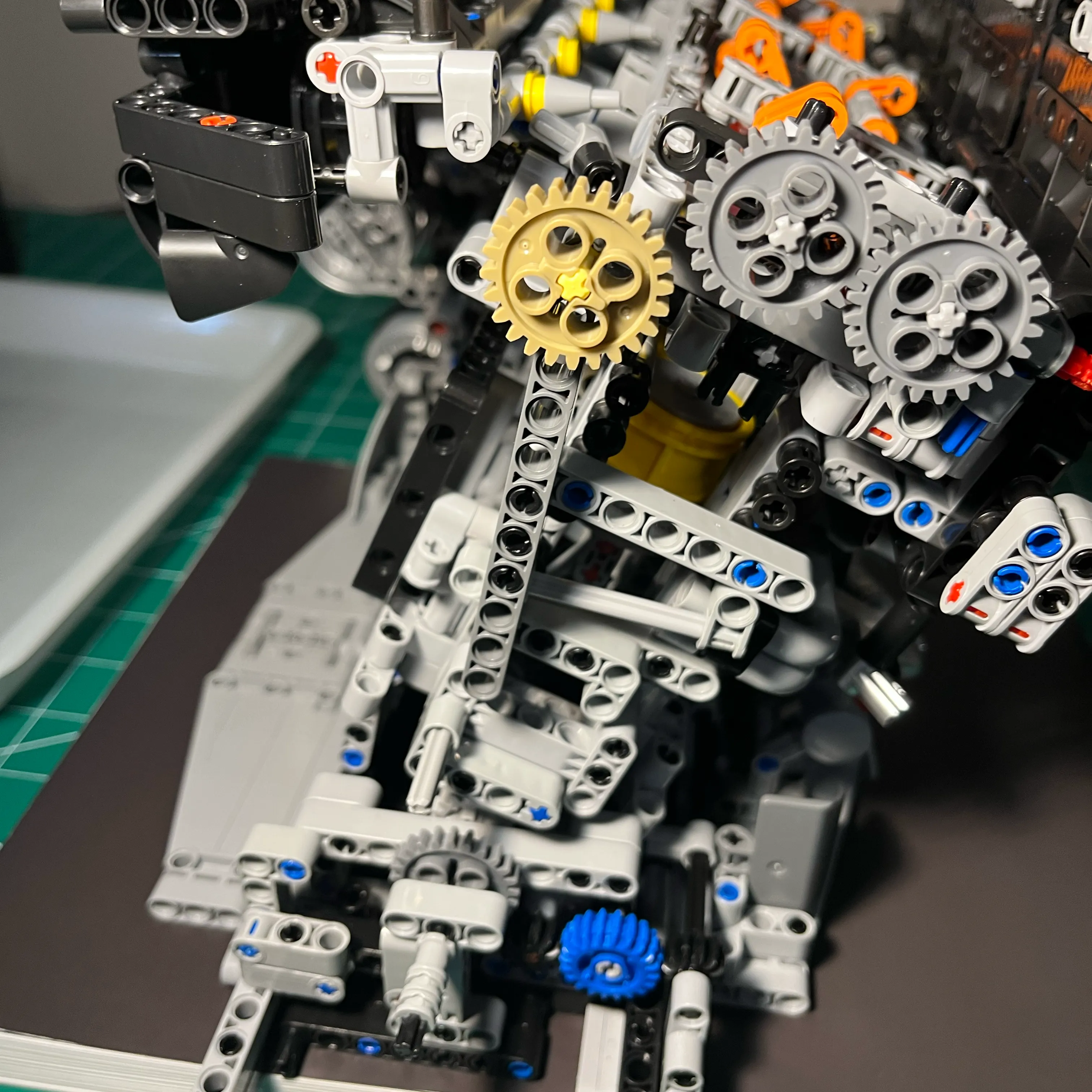
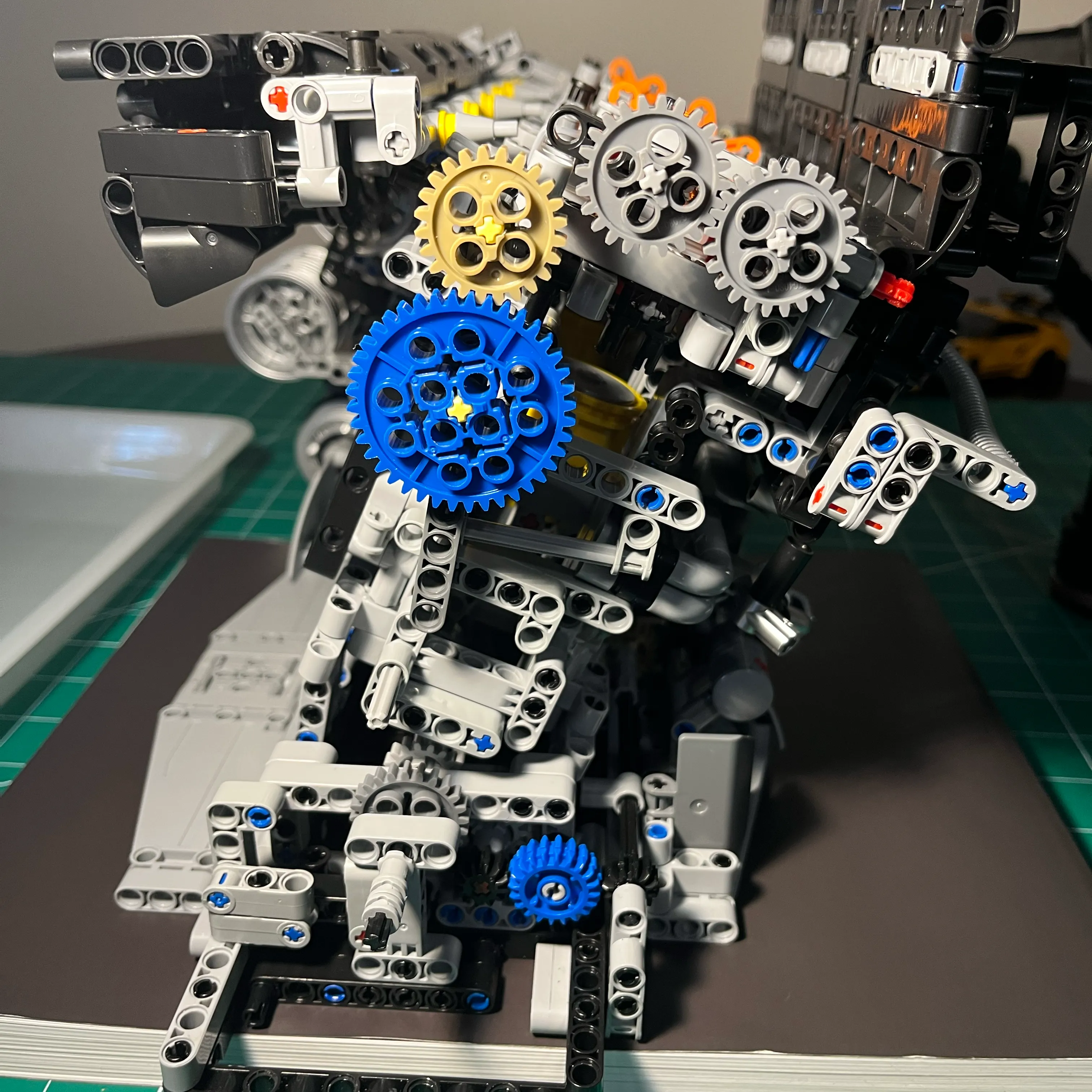
Large Light Gray Gear Install
Reviewing Cam Drive System
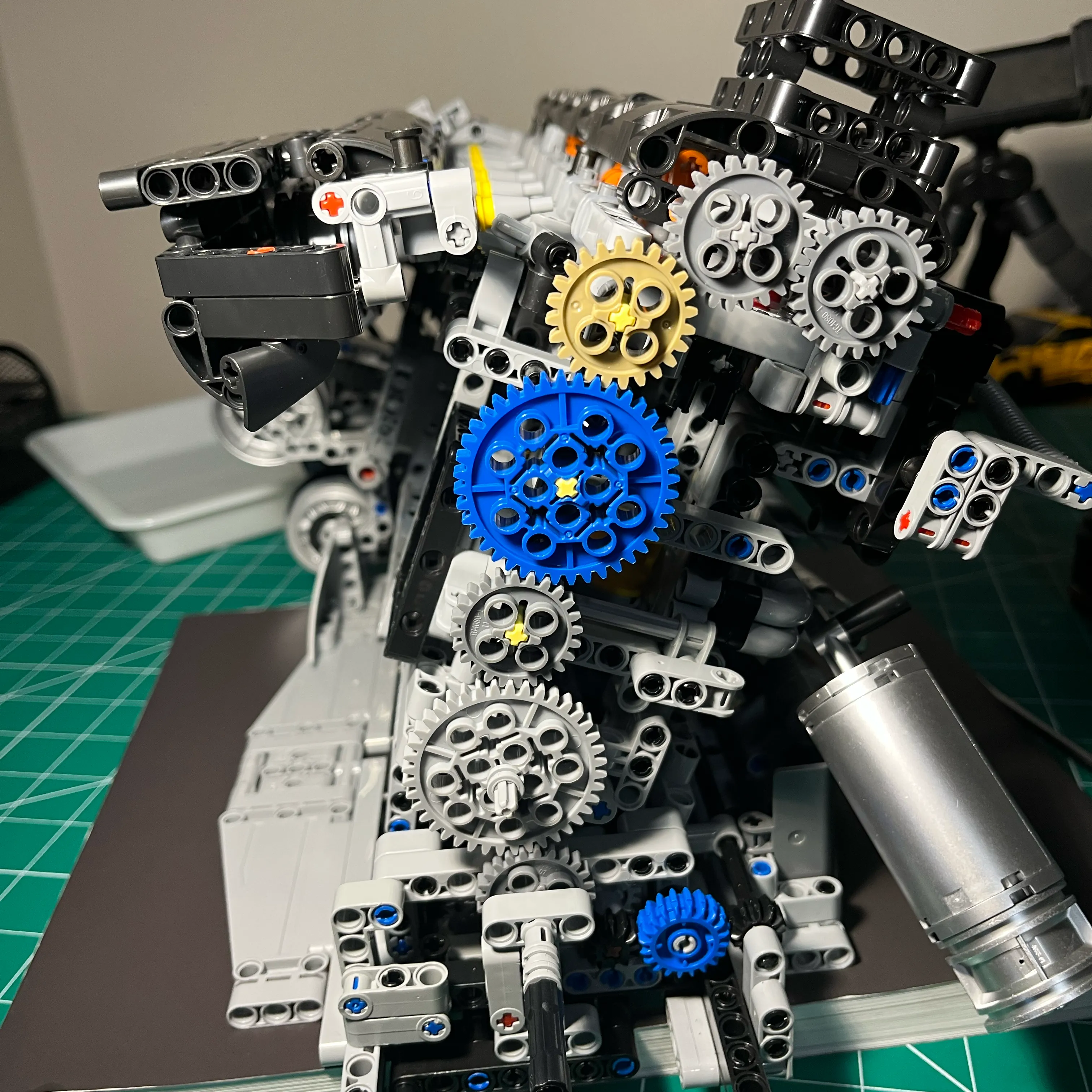
All Gears Meshed - View from Straight On
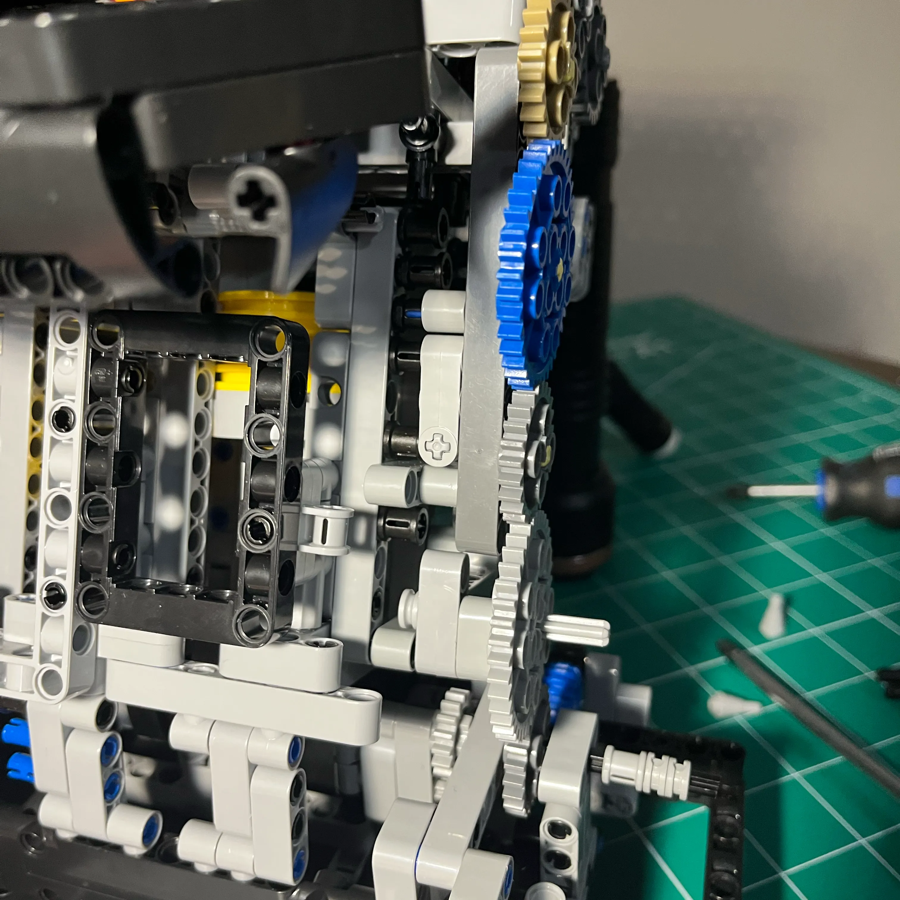
All Gears Meshed - View from LHS
Cam Drive Gears Assembly - Lock Tensioner In Place
This is the final step: applying the lateral pressure. By locking the pivot beam into this specific horizontal position, the entire gear train is pressed into a precise mesh that doesn’t slip, even when driven by a power drill.
Final Thoughts
This redesign transformed the NifeliZ L6 from a static display model into a robust mechanical system capable of handling high-speed rotation.
To see the videos of this gear-drive in action—including the high-speed drill test where I found the RPM limits of the pistons—check out the main NifeliZ L6 Model Engine post.