NifeliZ L6 Model Engine
2026-04-06
Assembling the NifeliZ L6: A hands-on dive into mechanical systems and engine architecture.
NifeliZ L6 Engine Kit
After thoroughly enjoying the LEGO® Back to the Future DeLorean build, I wanted to find a more challenging automotive inspired LEGO® kit to build. Nothing currently available struck my fancy.
I found the NifeliZ L6 Engine kit on Amazon ($140 CAD / $100 USD), thought it looked interesting, and went ahead and purchased it. There is also a V8 version. I chose the inline 6 model because I have Paul Walker’s Toyota Supra Technic build on my shelf, and I thought a 2JZ-style engine would complement it perfectly.
The NifeliZ L6 Engine Model is a LEGO® Technic inspired take on the inline 6 engine. Here’s the NifeliZ marketing material:
While I’ve shared quite a few custom modifications and redesigns in my videos, I want to give proper credit to Nifeliz for the foundation—it’s a great building experience and serves as a fantastic canvas for any mechanical enthusiast.
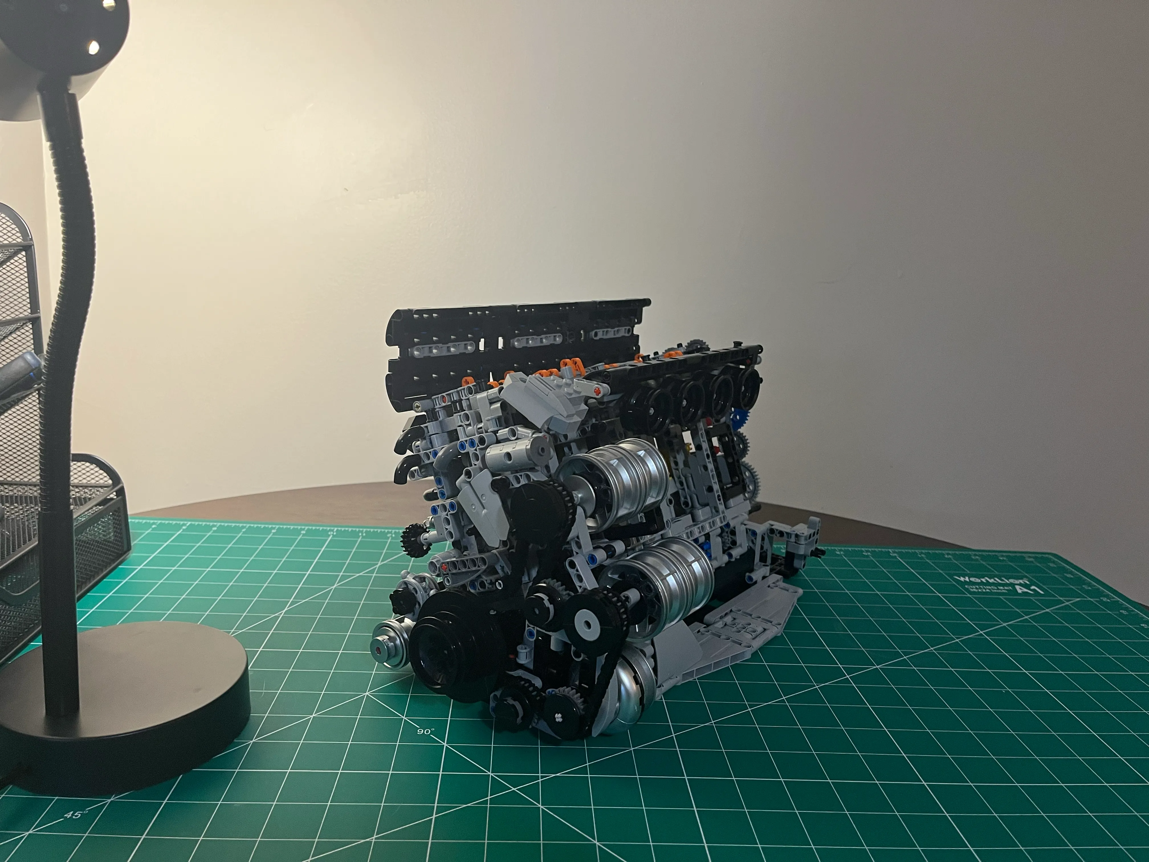
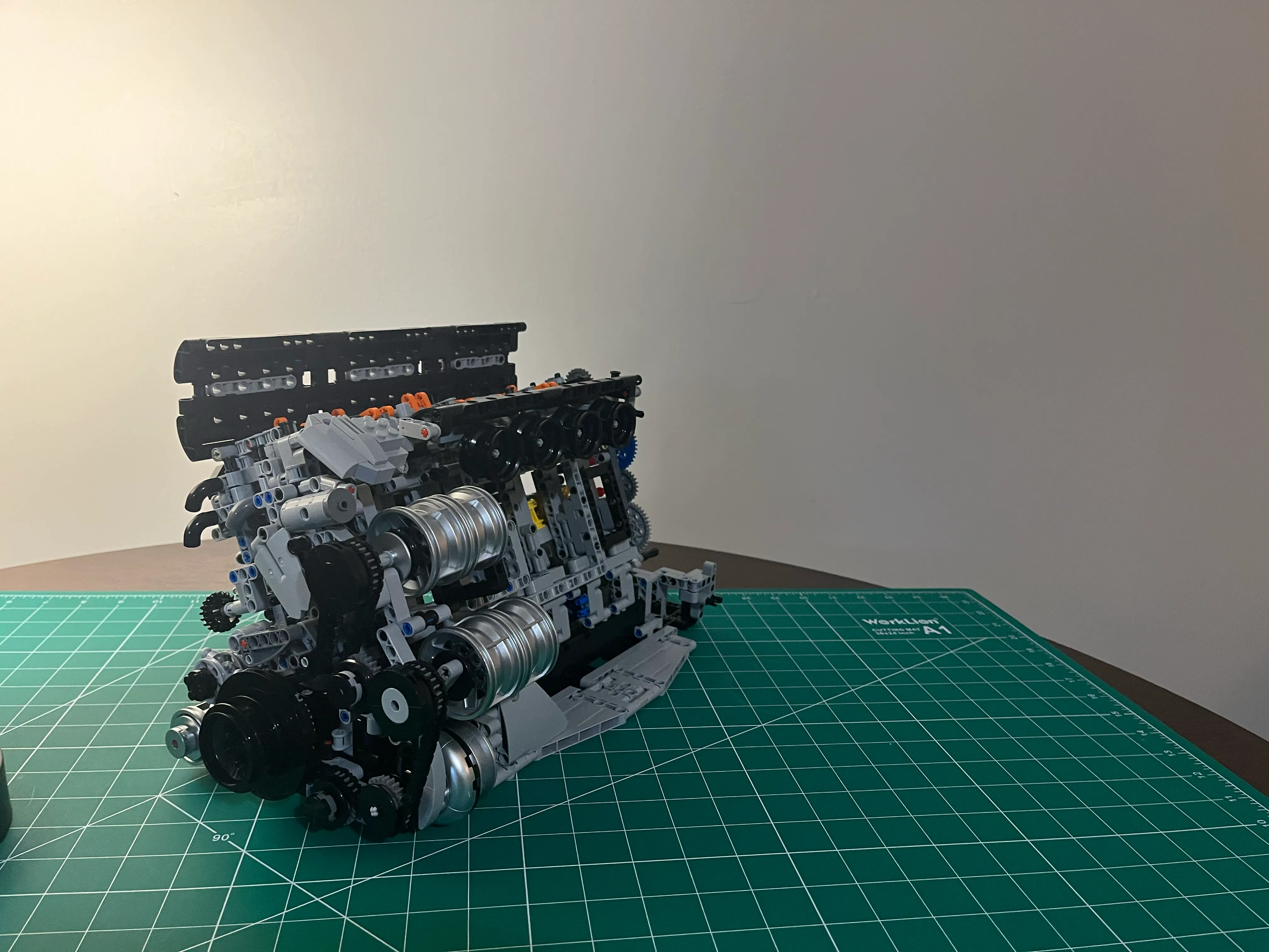
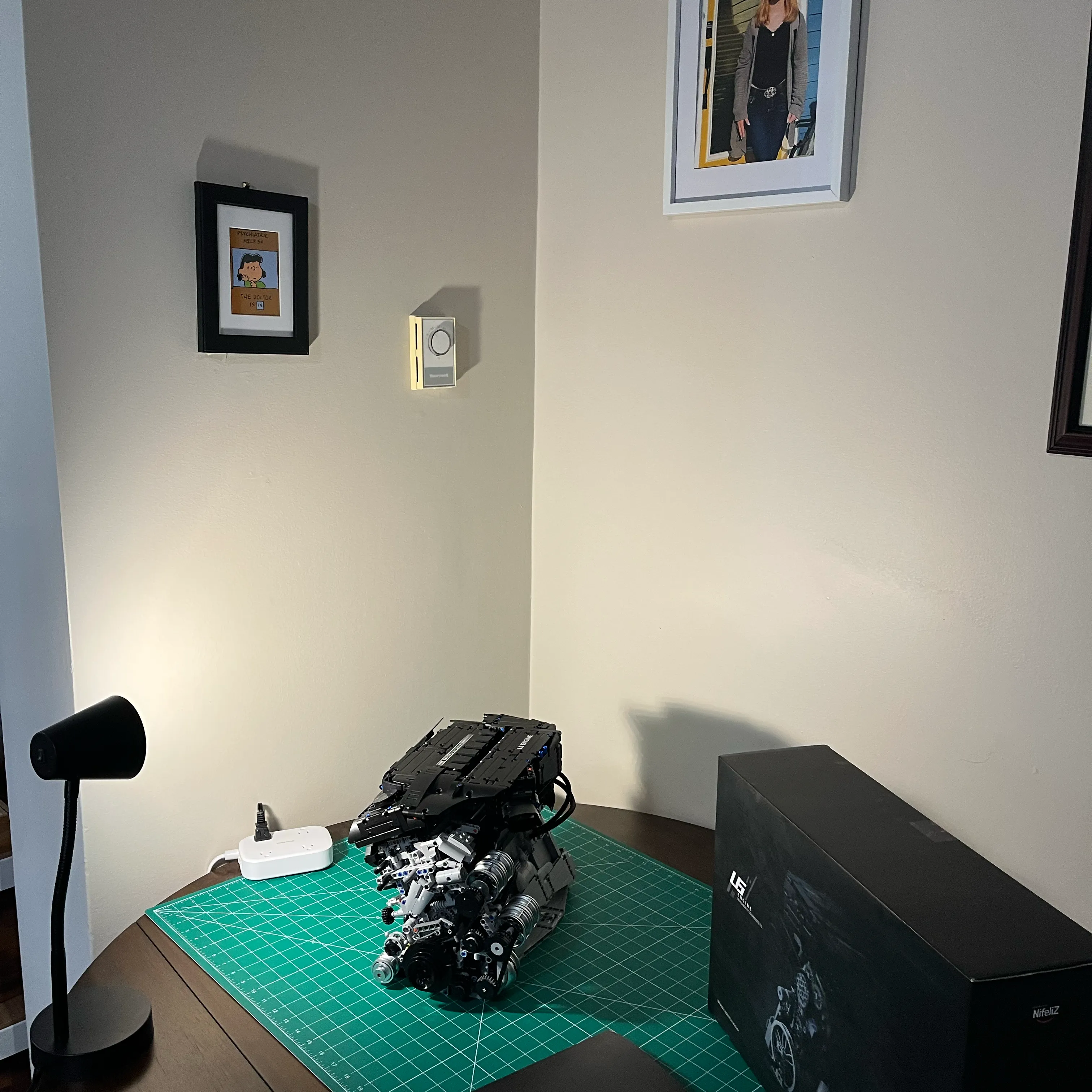
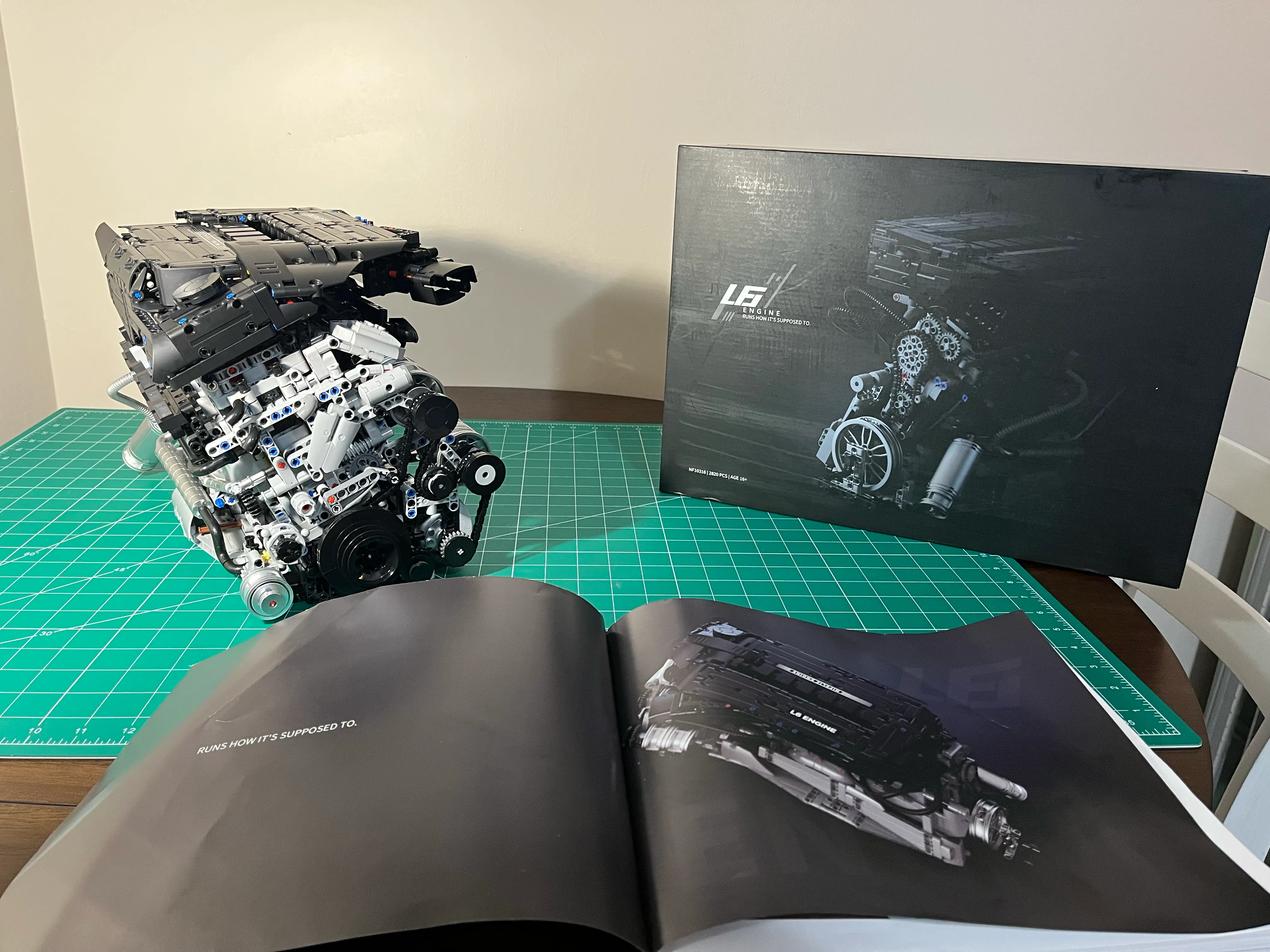
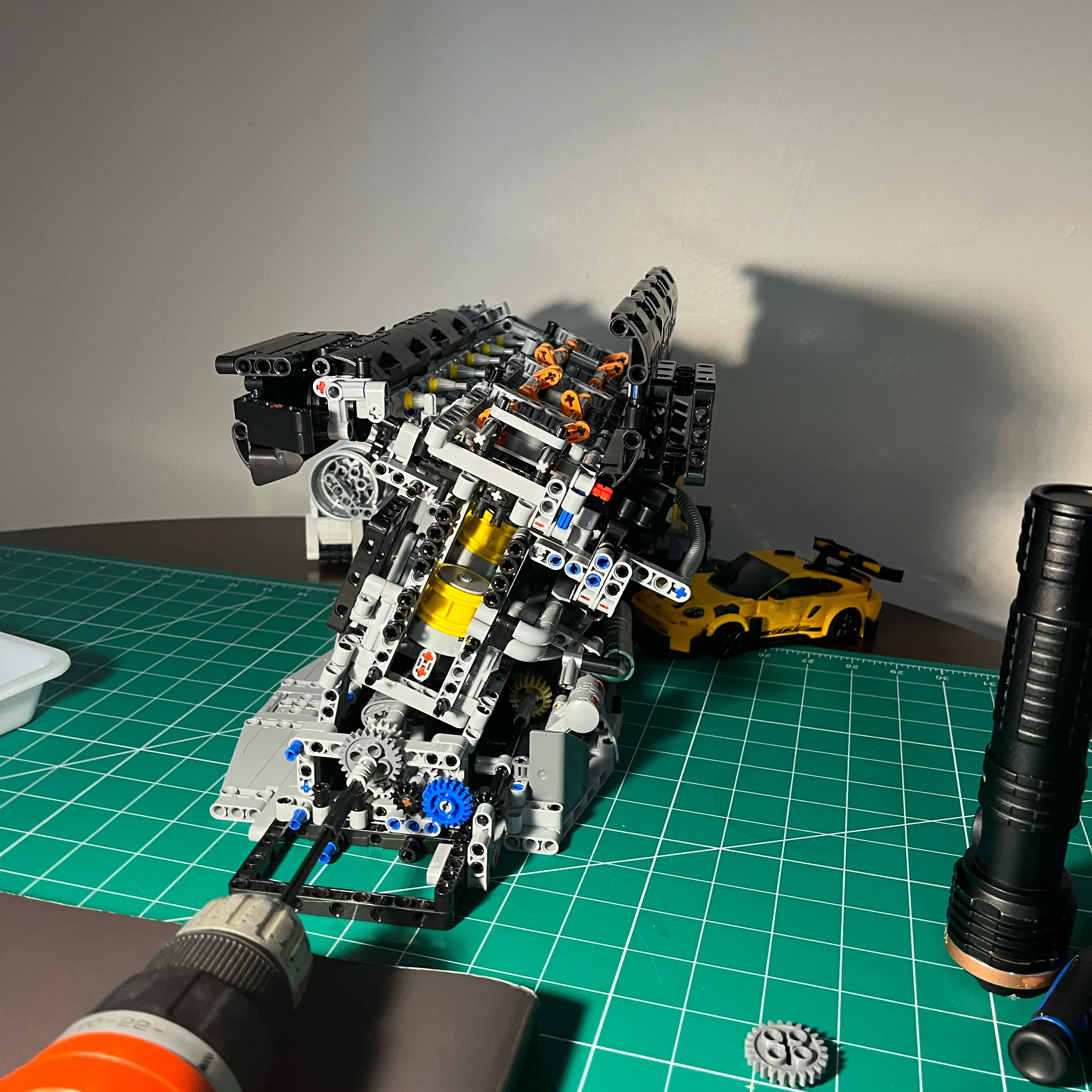
At 15 inches long, 7 inches wide, and 10 inches high, the model is a substantial presence on a desk or workbench. It features a realistic aesthetic, including a turbocharger and several front-end accessories.
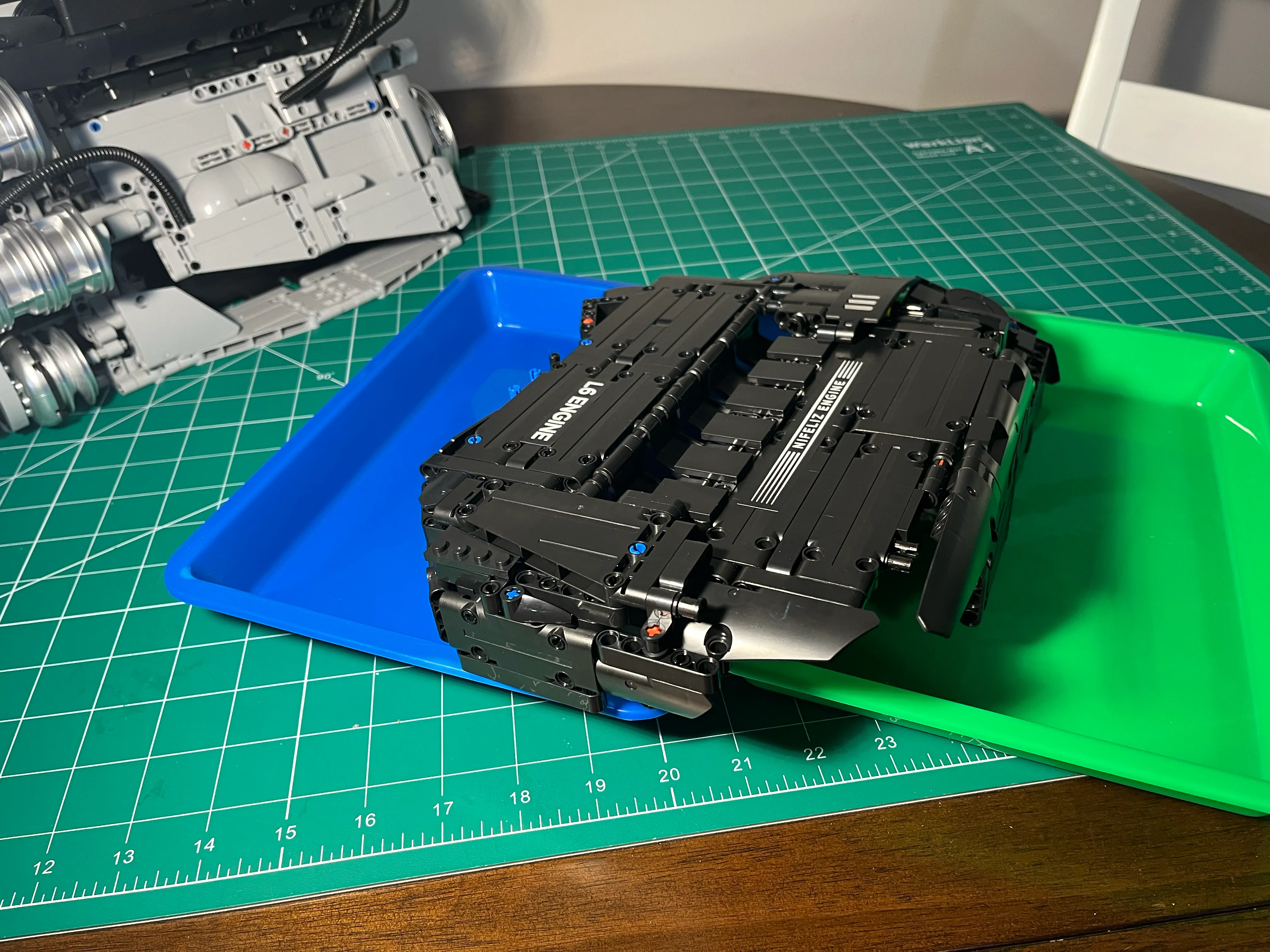
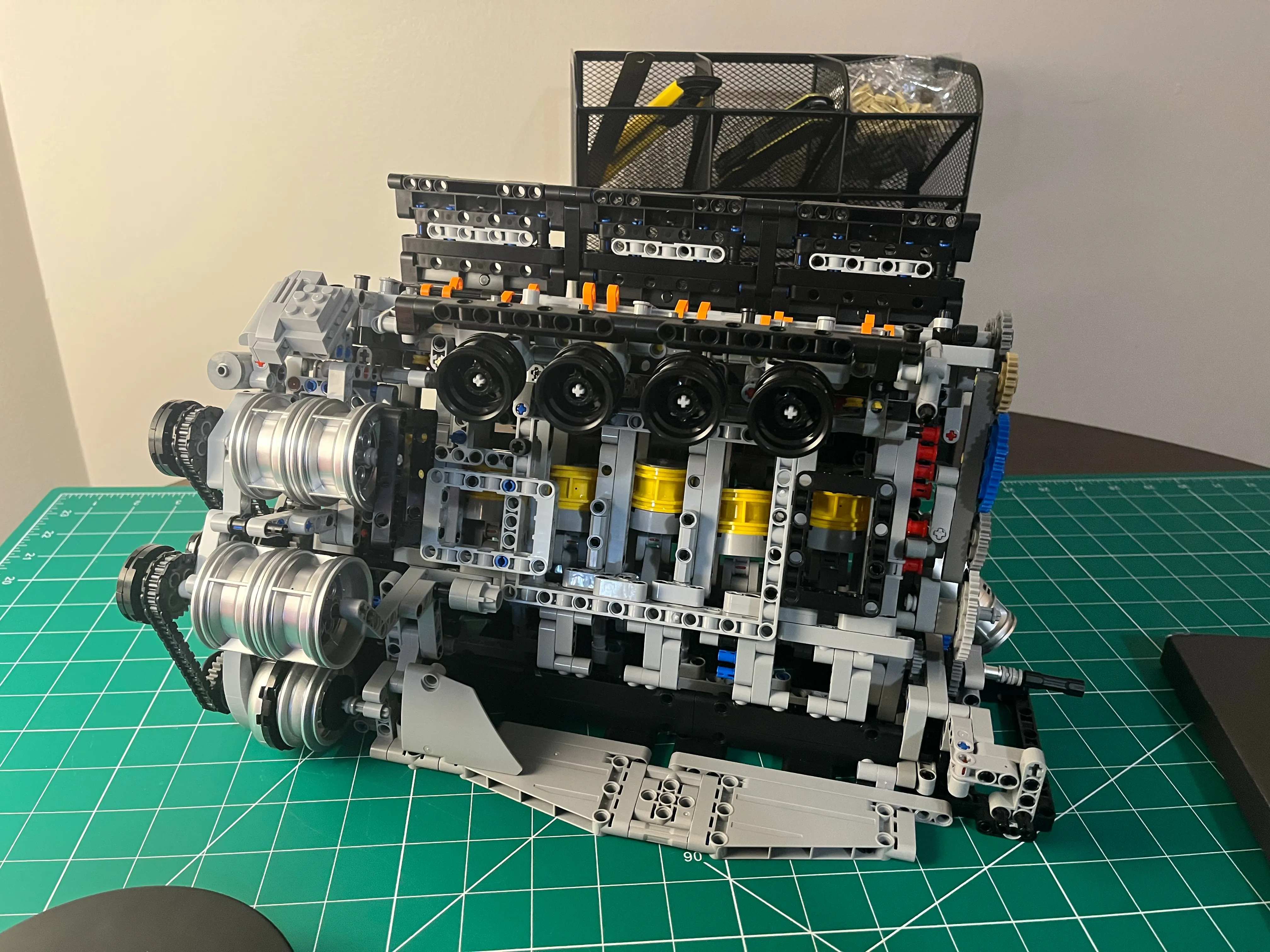
Fully Assembled
Here’s a picture of the completed build. It looks really great, IMO.
Engine Demo Videos
Here is the final result: a 90-second run using the power drill, capturing the front accessories, the exposed pistons, and the new bulletproof rear gear drive operating flawlessly at varying speeds.
Rear View
Here’s a quick clip where I manually turn the engine over, viewed from the rear of the engine.
Front View
Here’s another clip where I manually turn the engine over, viewed from the front of the engine.
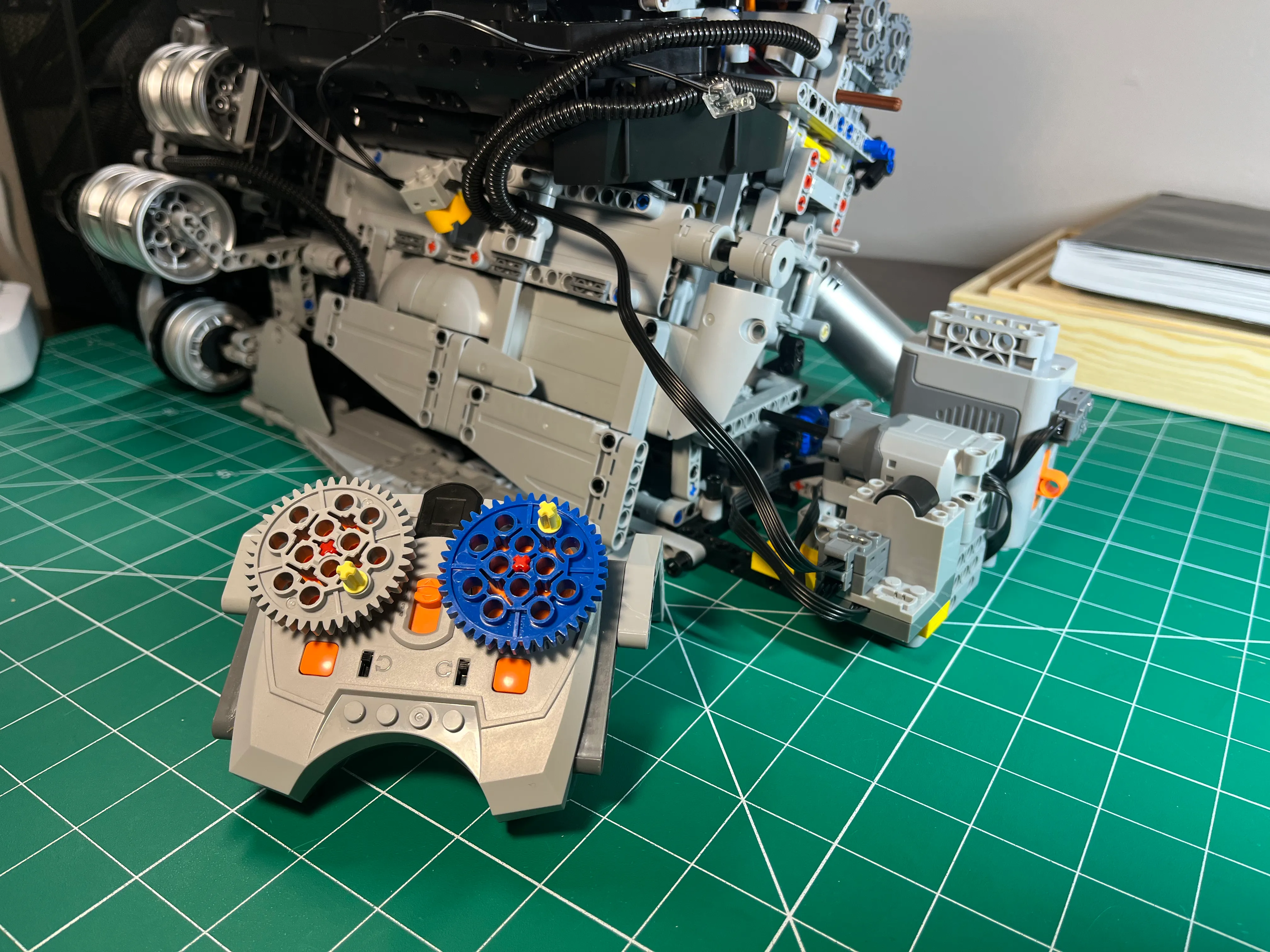
Technic Motor Powered - with Remote Control
To add the cherry on top, I installed a Technic XL motor on the crank shaft at the rear of the engine.
NifeliZ L6 Engine Remote Control Demo
Technic XL Motor Install
The Technic XL motor, IR receiver, battery pack, and remote viewed from an angle behind and to the left of the L6
engine.
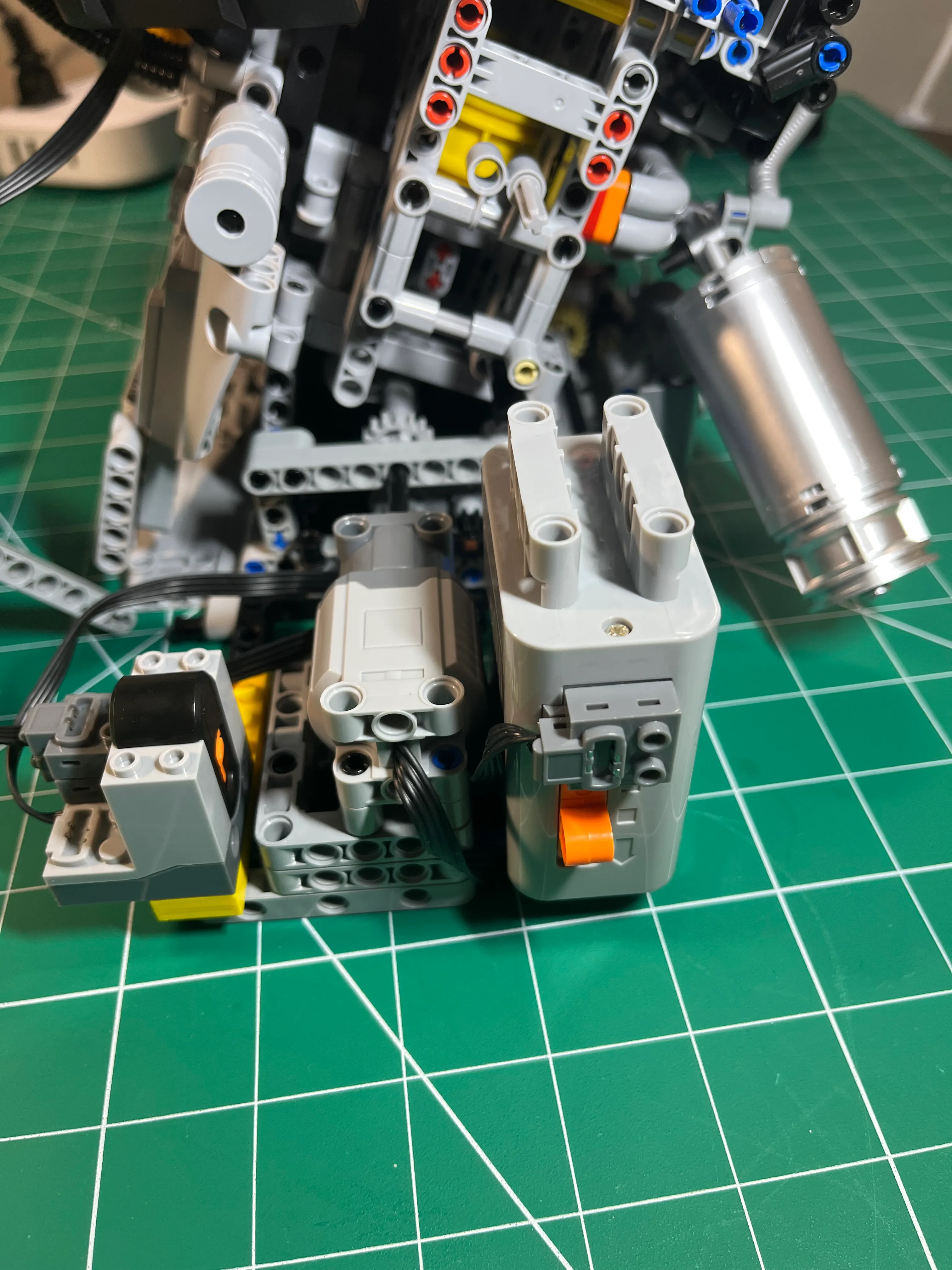
The Technic XL motor setup, viewed straight on from behind the L6 engine.
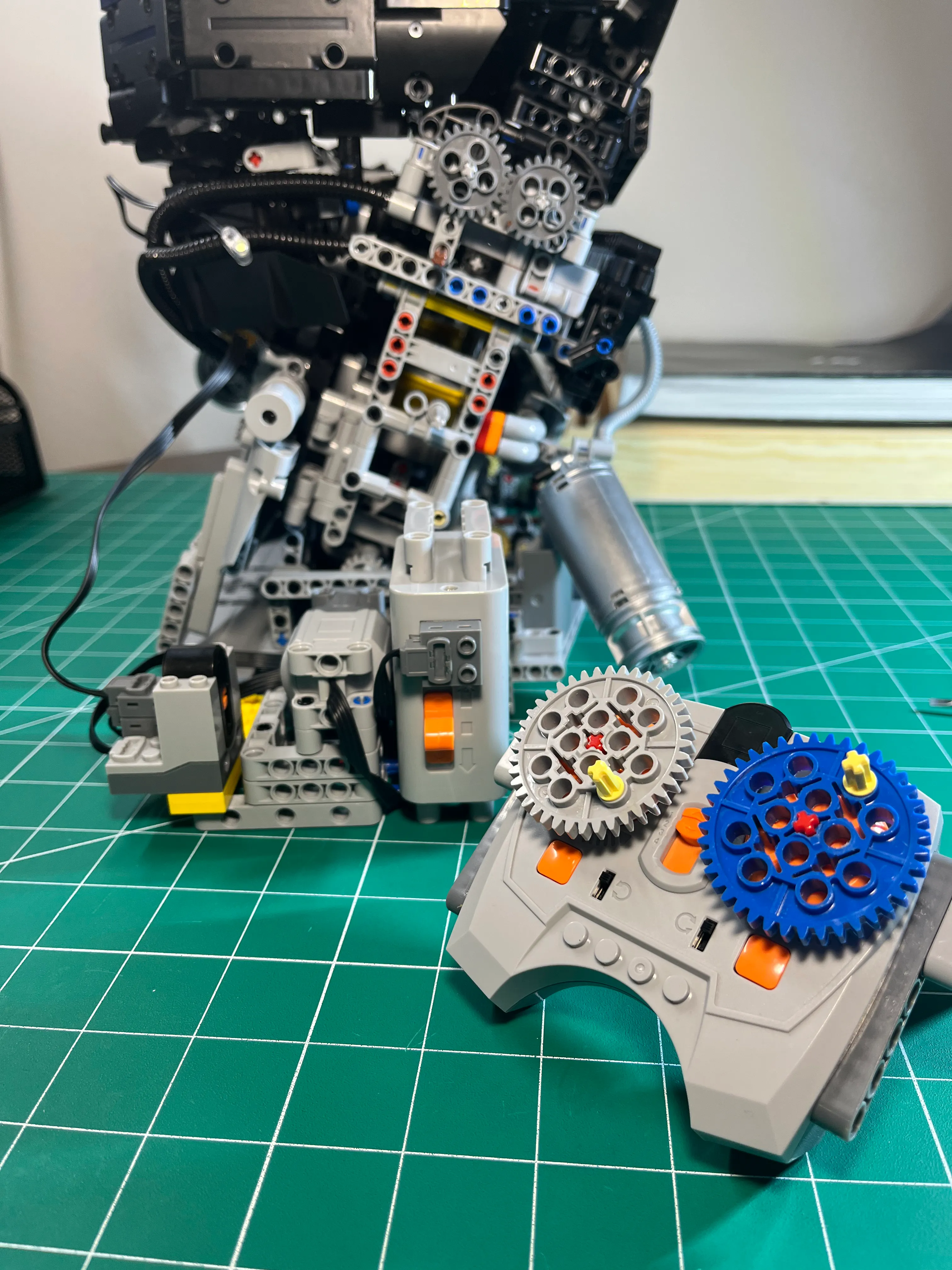
The Technic XL motor setup, viewed at a downward angle. This shows the layout and attachment points, and the neat and
tidy routing of the wires.
Technic Motor Kit
Here’s the 9-in-1 Technic Motor Kit I ordered from Amazon for $42 CAD.
Engine Cover
The engine cover is really nice, and I don’t want to just let it sit on top of the engine. It doesn’t look great when the engine cover is not level. Any bump and the engine cover can move.
I was pissed that the nice engine cover that is the final part of the build does not include any mechanical fasteners. From what I can tell, the instructions tell you to just lay the cover on top of the engine. I could not believe it. I was able to find enough left over parts to rig something up, but it’s still not to my liking.
Rotating Assembly Clearance
The assembly instructions did not go into depth on proper crank and piston alignment procedures. The existing steps have you assemble the crank and pistons and add it to the engine frame, then assemble the engine block and cylinder head, and install it over top of the pistons.
By the time you get to the steps where the gears are added to the engine to allow spinning the crank inside the block, any alignment issues are nearly impossible to fix. Access to the crank and pistons is completely covered up. You have to strip away the cylinder head and all exterior engine components attached to the block just to see the crank lobes. Even then, the bottom side of the engine has zero visibility. Visualizing the binding points was brutal.
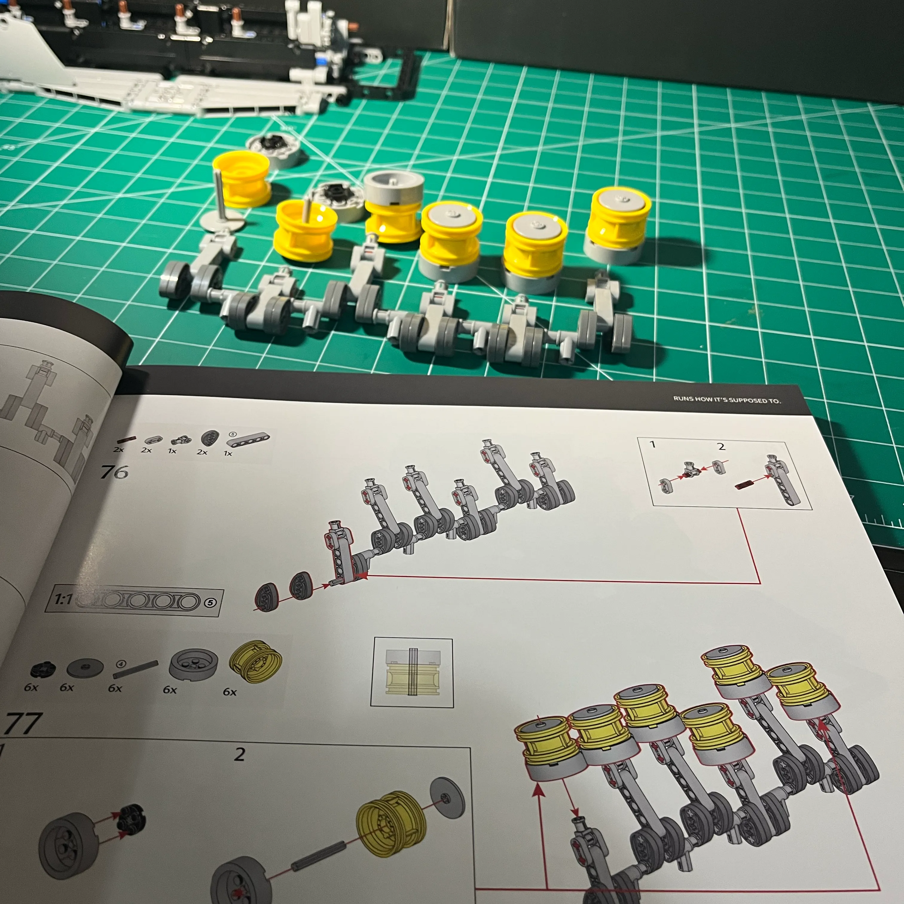
Here’s the crank assembled without pistons attached, and then installed in the frame. I turned the frame upside down to see how the pistons might look in their bores once the engine block is installed.
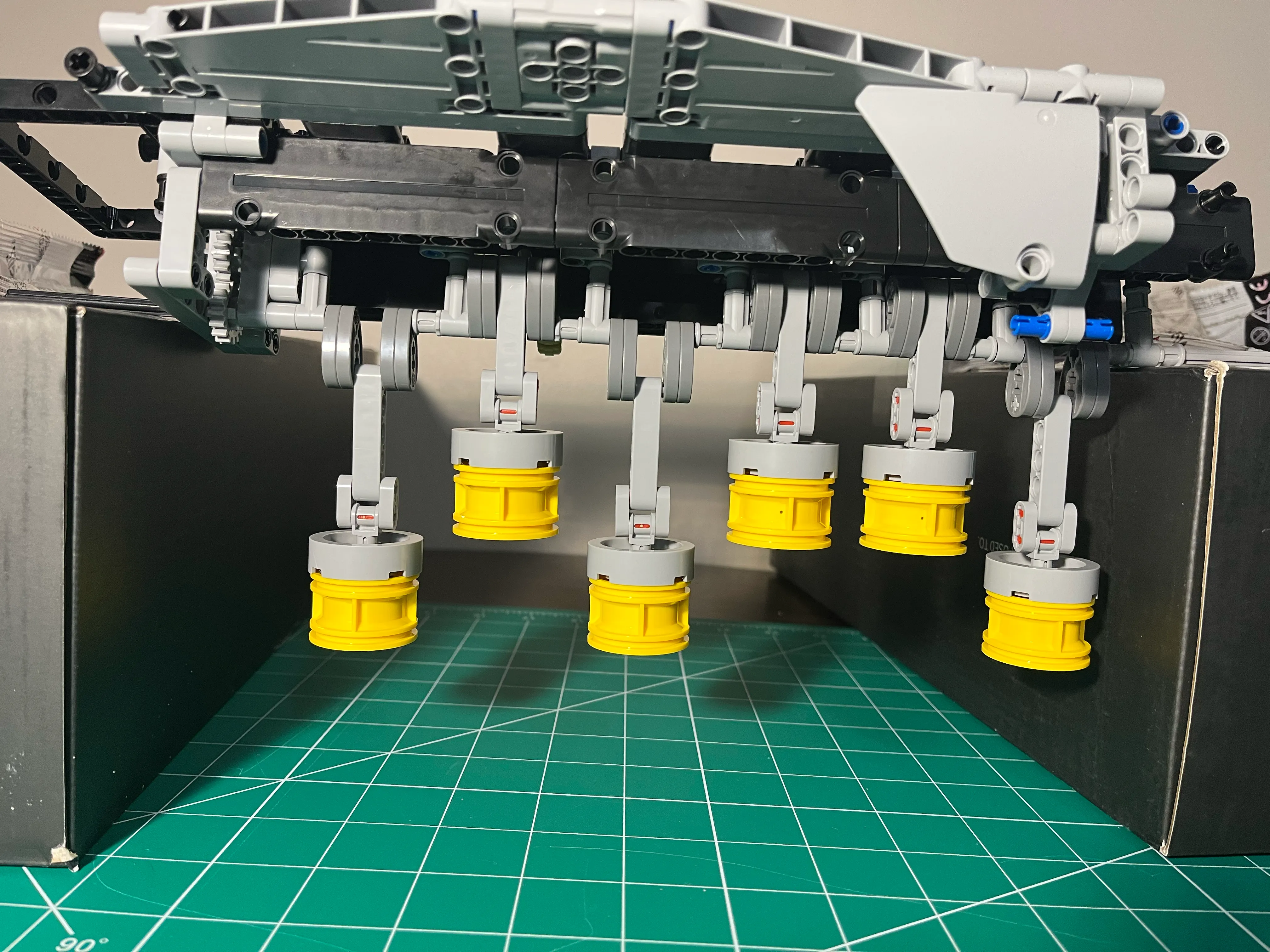
Before I realized the binding issues, I was on bag 29 out of 40. Here’s what I could see—not much at all. I had to tear down to find the problems.
The other side of the engine block had better visibility and gives a nice view of the pistons, but I still couldn’t see exactly where the binding was happening; I could only hear it.
I eventually noticed some crank lobes were hitting engine block cross members. A lobe is made up of 2 oval-shaped pieces using a connector. If that light gray connector on the midline protrudes too far, it can either hit the piston connecting rod or the engine block cross member.
What I had to do was check each engine block cross member and ensure there was enough clearance. This needs to be done iteratively, because adjusting clearance in one cylinder can change clearances in other cylinders.
Chamfering Crank Lobes
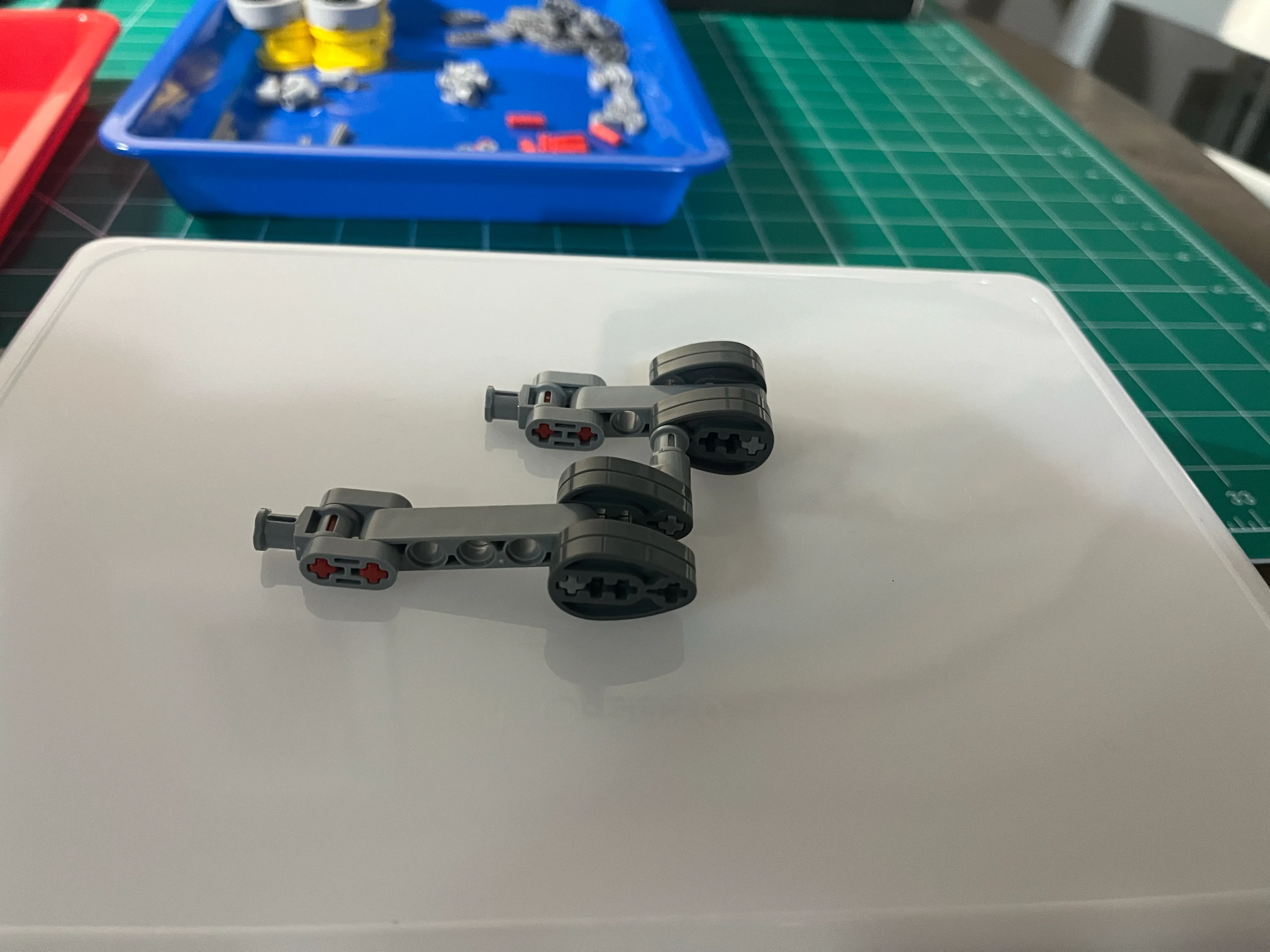
I found that the crank lobes were hitting structural components of the engine block, and were also interfering with connection rods rotating freely. I had to chamfer all the crank lobes to get the crank and connection rods to rotate freely. I used a Dremel and sand paper to chamfer the crank lobes. It looks rough, but it works well.
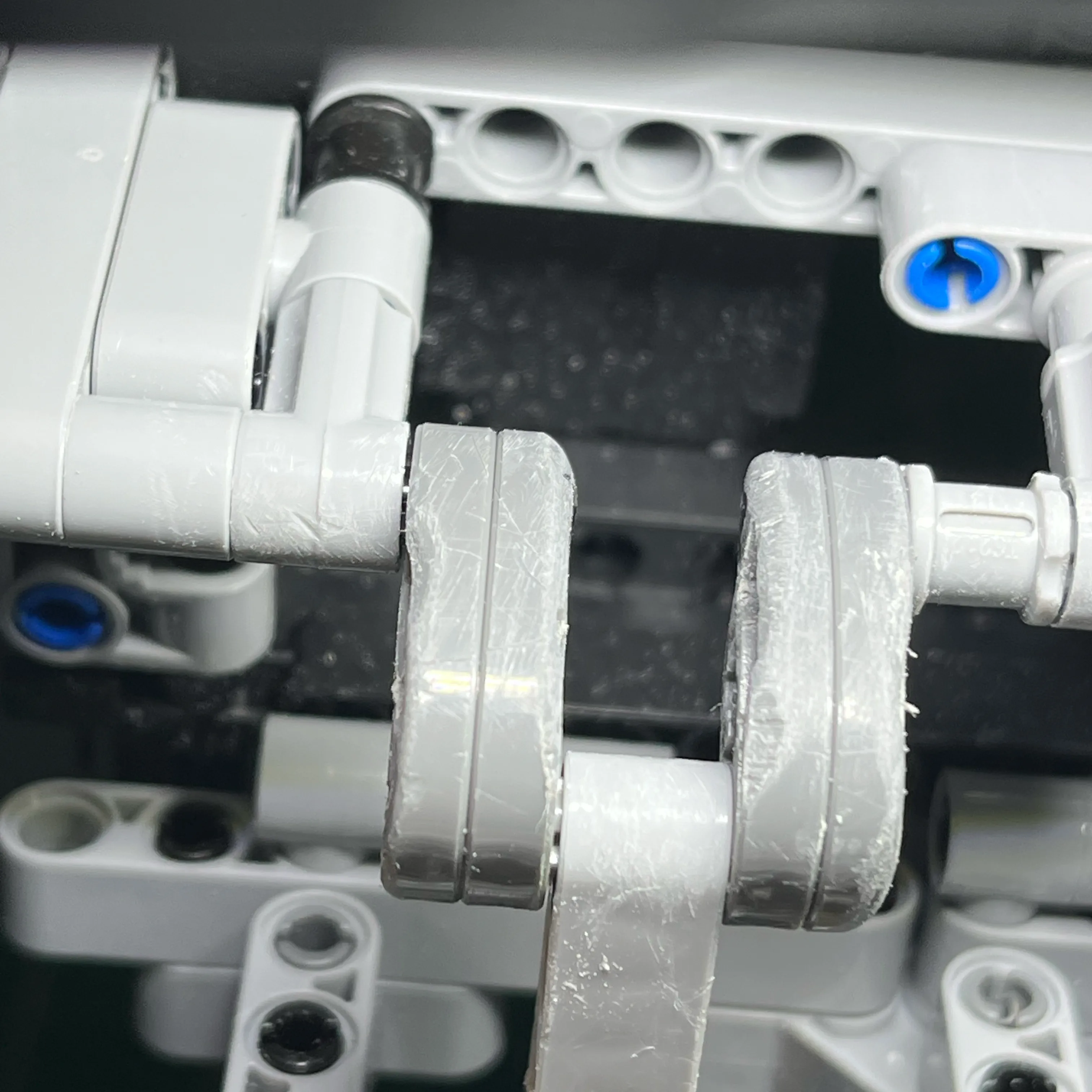
Here’s a connecting rod connected to 2 crank lobes, with the connecting rod close to TDC. The chamfering is visible on the outside of both crank lobes as well as on the inside of both crank lobes. All 6 cylinders had this chamfering work done.
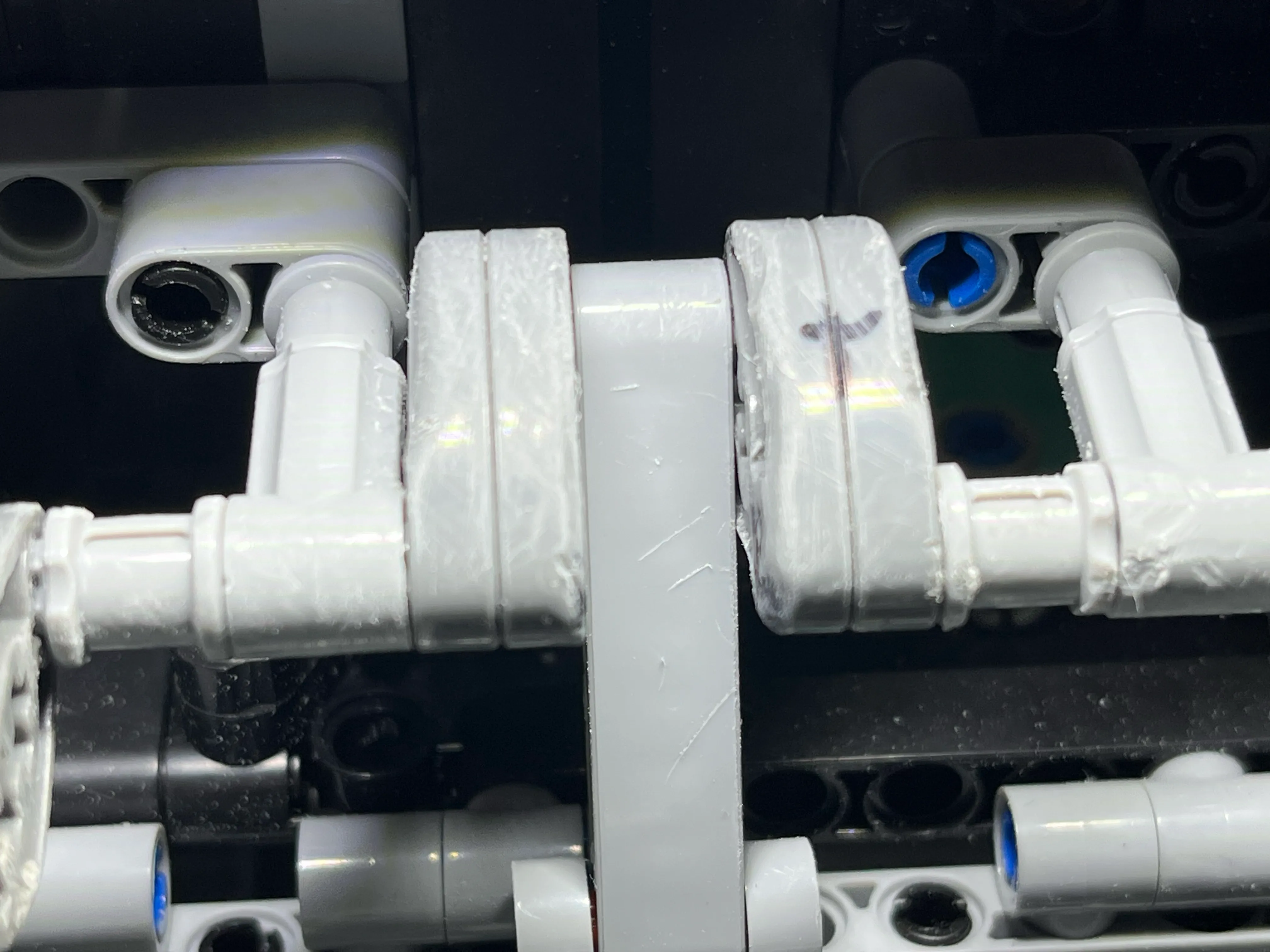
Here’s a view of crank lobe chamfering with the connecting rod close to BDC. This shows that when the connecting rods
sweep through the 2 crank lobes, the connecting rod can bind if the crank lobes are too close together.
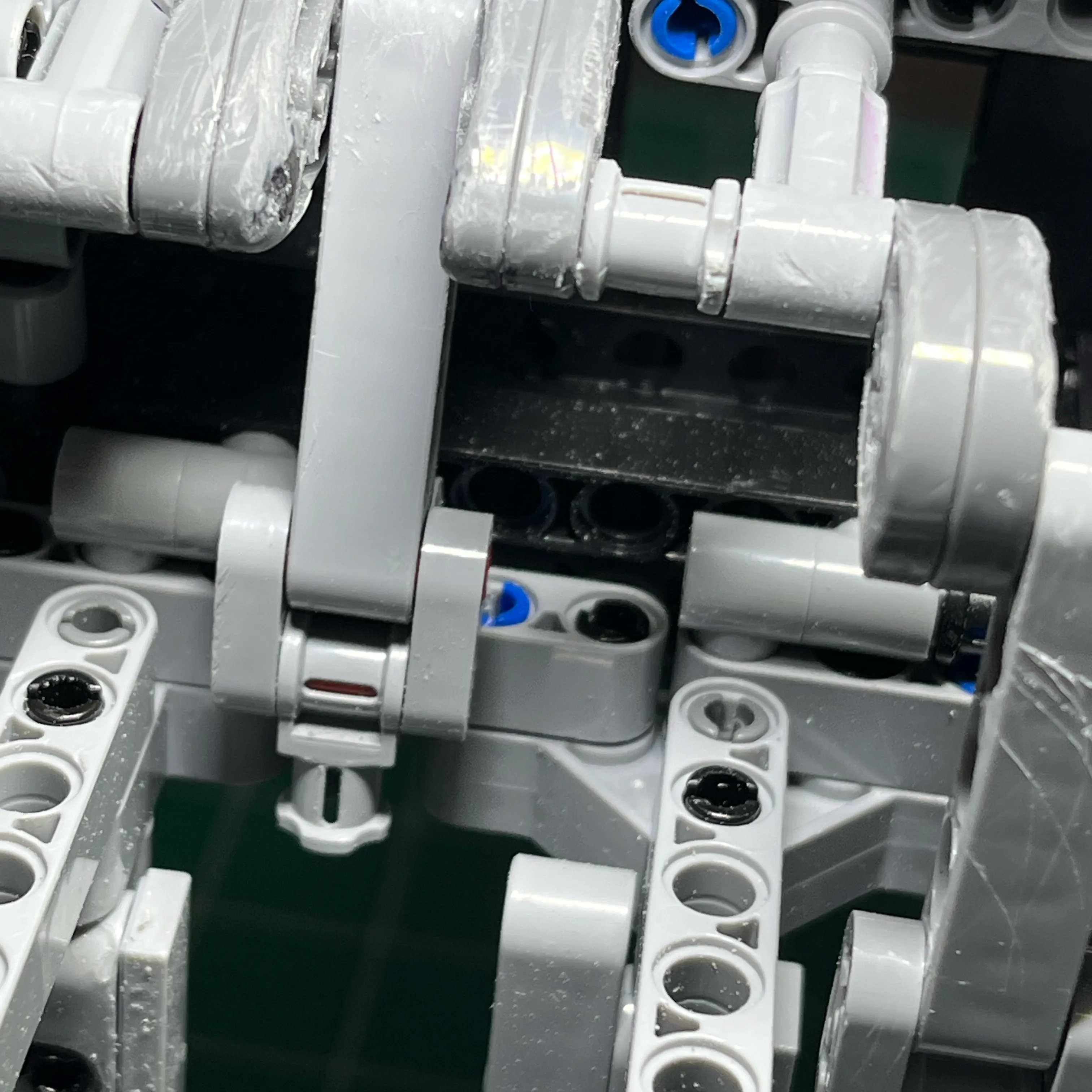
Here’s a view of crank lobes showing where the crank lobes attach to the crank, to see the chamfering around the
connection.
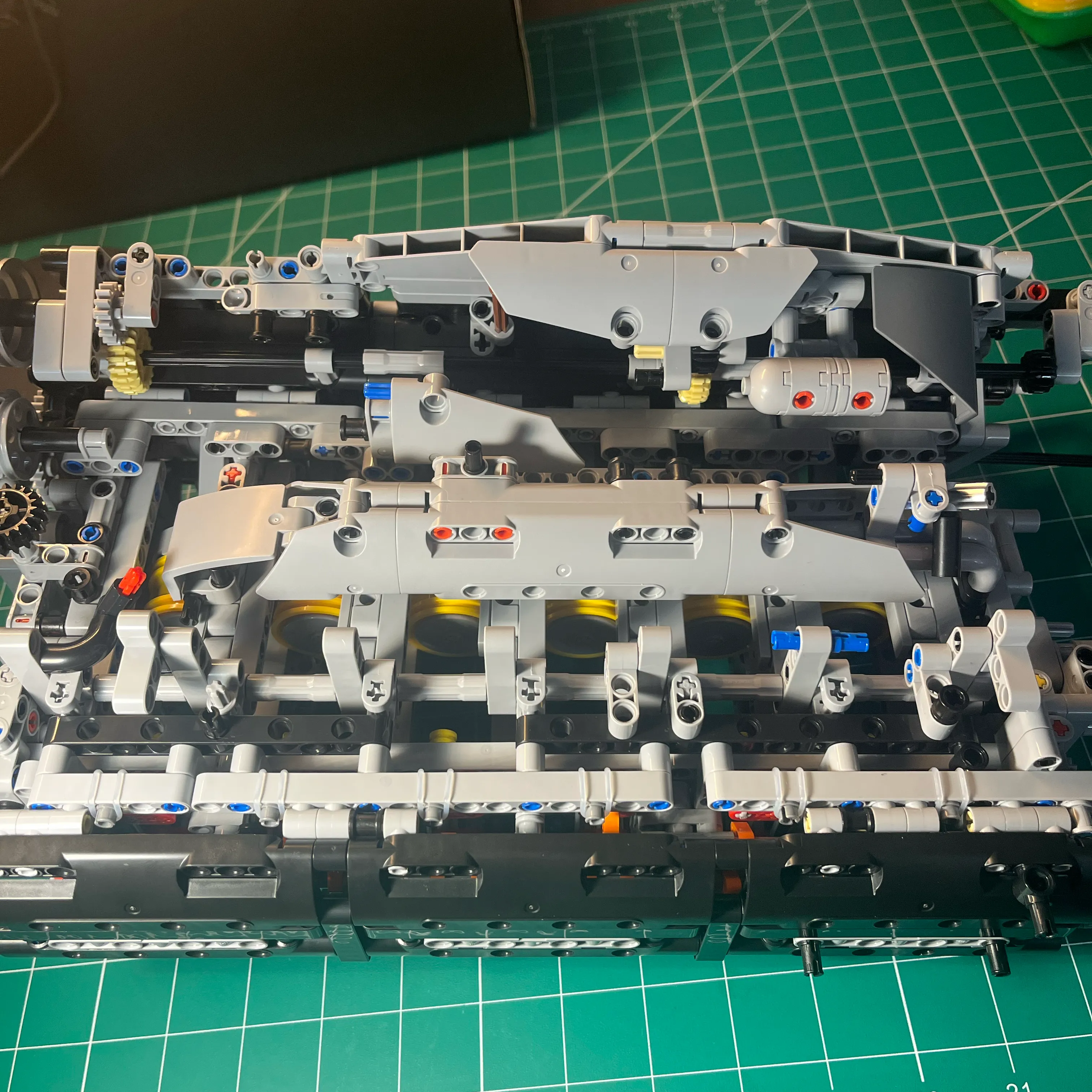
Here’s a view of the engine torn down for chamfering work, with the engine block disconnected on one side and the
engine base sitting flat on the table. This gives a good look at the rotating assembly and the chamfering. Pistons are
still attached.
Here’s another view of the torn down engine for chamfering work, with the engine upside down. This allows the
connecting rods to hang freely, letting me rotate the crank to check for clearance issues. The engine block is
disconnected from the base on one side, so I can flip up the base to do the chamfering work.
Cylinder 6 Binding
I found out using a power drill that applying axial load on the crank pushes the crank through the lobe in cylinder 6, which causes the cylinder 6 connection rod to bind when rotating through the crank lobes.
Here’s a good view of a piston, connecting rod, and crank lobes. There are 4 oval shaped pieces, 2 on either side of the connecting rod.
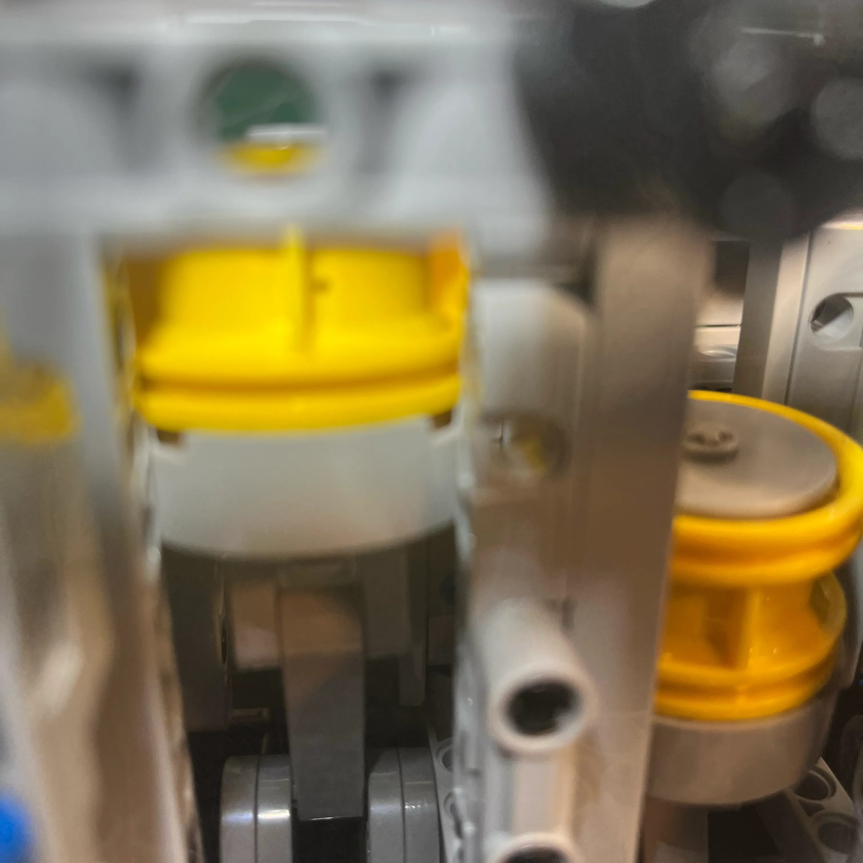
Here’s a view of the connecting rod and crank lobes during initial assembly.
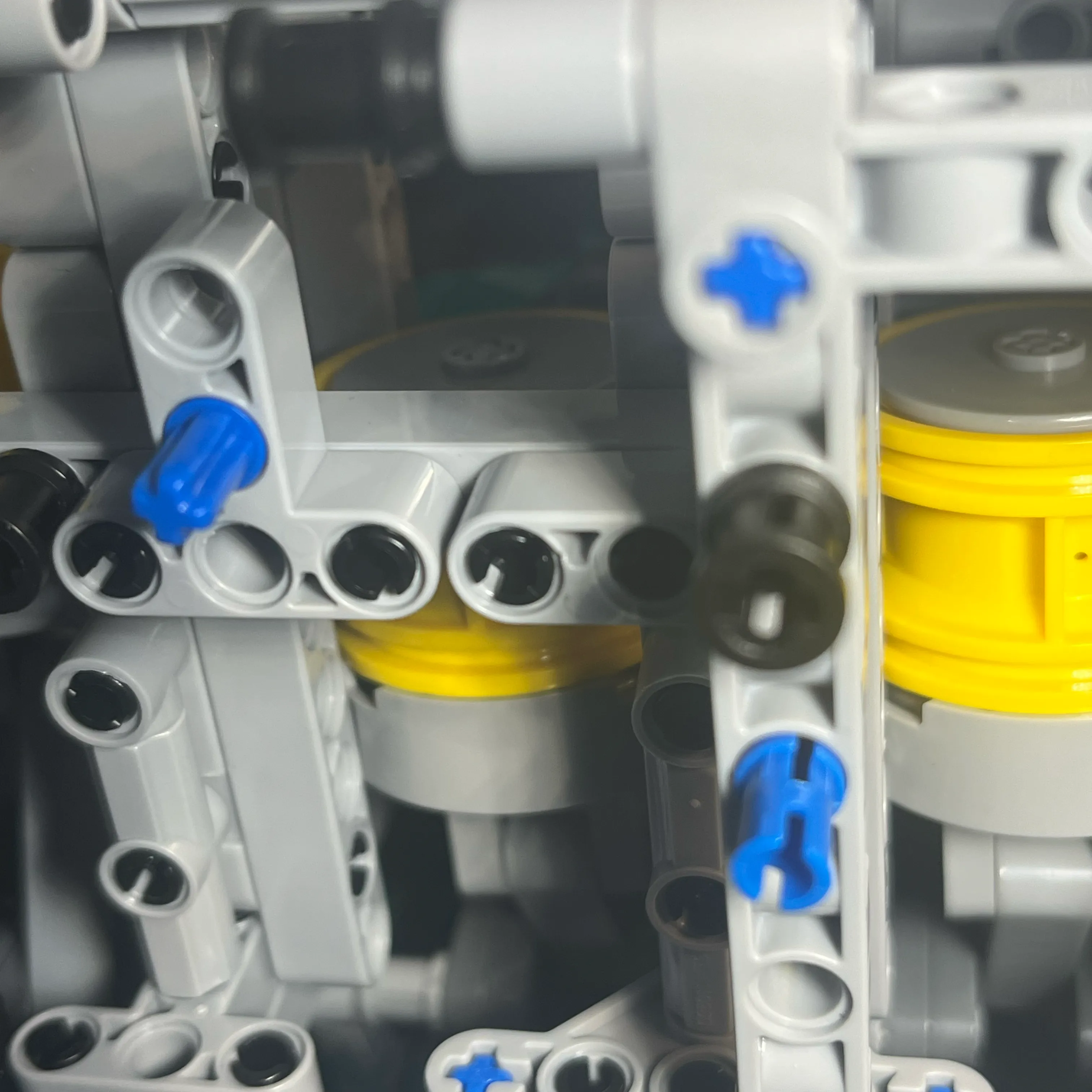
The binding issue can be seen clearly in this picture. Look at the connecting rod on the bottom. The 2 crank lobes on the bottom aren’t connected to anything at this point of the build. Focus on the other 2 crank lobes on the upper side of the connecting rod. There’s a pin that goes through the large end of the crank lobes and connecting rod, allowing the connecting rod to rotate on the journals, represented by the large end of the oval shaped crank lobe.
Look at the connection of those crank lobes to the crank. You can see the light gray + protruding past the crank lobe. That is the binding issue. I didn’t know at assembly time that even that small amount of protrusion would cause binding issues.
Cylinder 6 crank lobes on the very back of the engine are connected to a long pin that the hand crank is attached to that is used to spin the engine over. Applying force along the crank centerline can cause the pin on the crank lobe to protrude through both crank lobes, which causes binding in cylinder 6.
Removing and reinstalling gears on the back of the engine, or even hooking up a power drill to the crank to spin the engine over are examples of forces that are enough to cause the crank / rod binding issue in cylinder 6.
To prevent the cylinder 6 binding issue, I added 3 small collars around the crankshaft pin, that provide resistance and help prevent the crankshaft from protruding through the cylinder 6 crank lobes.
Checking Clearances and Reattaching Pistons
Checking for Crank Protrusion in Cylinder 6
Purposely Causing Cylinder 6 Crank Protrusion
View with crank gear and collar added
View of cylinder 6 crank lobe after installing crank gear and collar with too much force
View of drill attached to crank, to test clearances
View of engine upside down while reattaching cylinder 6 piston to connecting rod
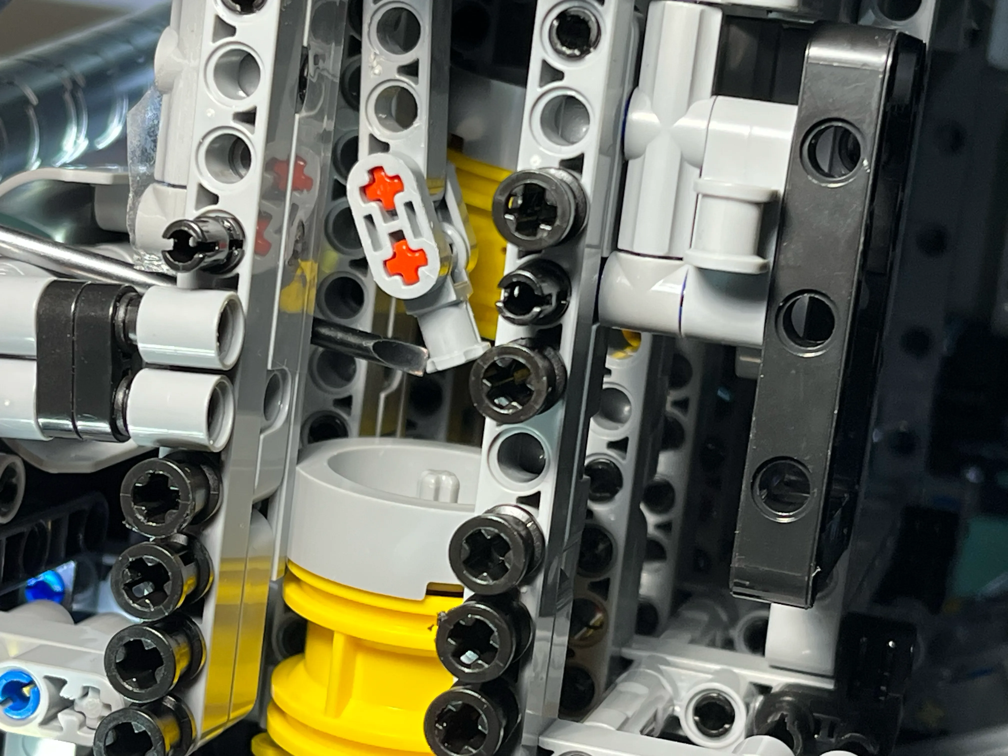
Attaching the piston to the connecting rod without taking the cylinder head off is a very tedious. It’s impossible to see what you are doing with the engine upright without having specialized cameras and lighting. The solution that I found worked best was to turn the engine upside down, and use gravity to align the connecting rod with the center of the piston. The piston has an edge that you can keep centered to make sure the pin on the piston aligns with the orientation of the connector on the connecting rod. To connect the piston to the connecting rod, move the piston up to meet the connecting rod, tip the engine from side to side slightly to get them aligned, and use a small screwdriver to gently nudge the connector onto the piston. Then you can use more force with the screwdriver to securely attach the connecting rod to the piston.
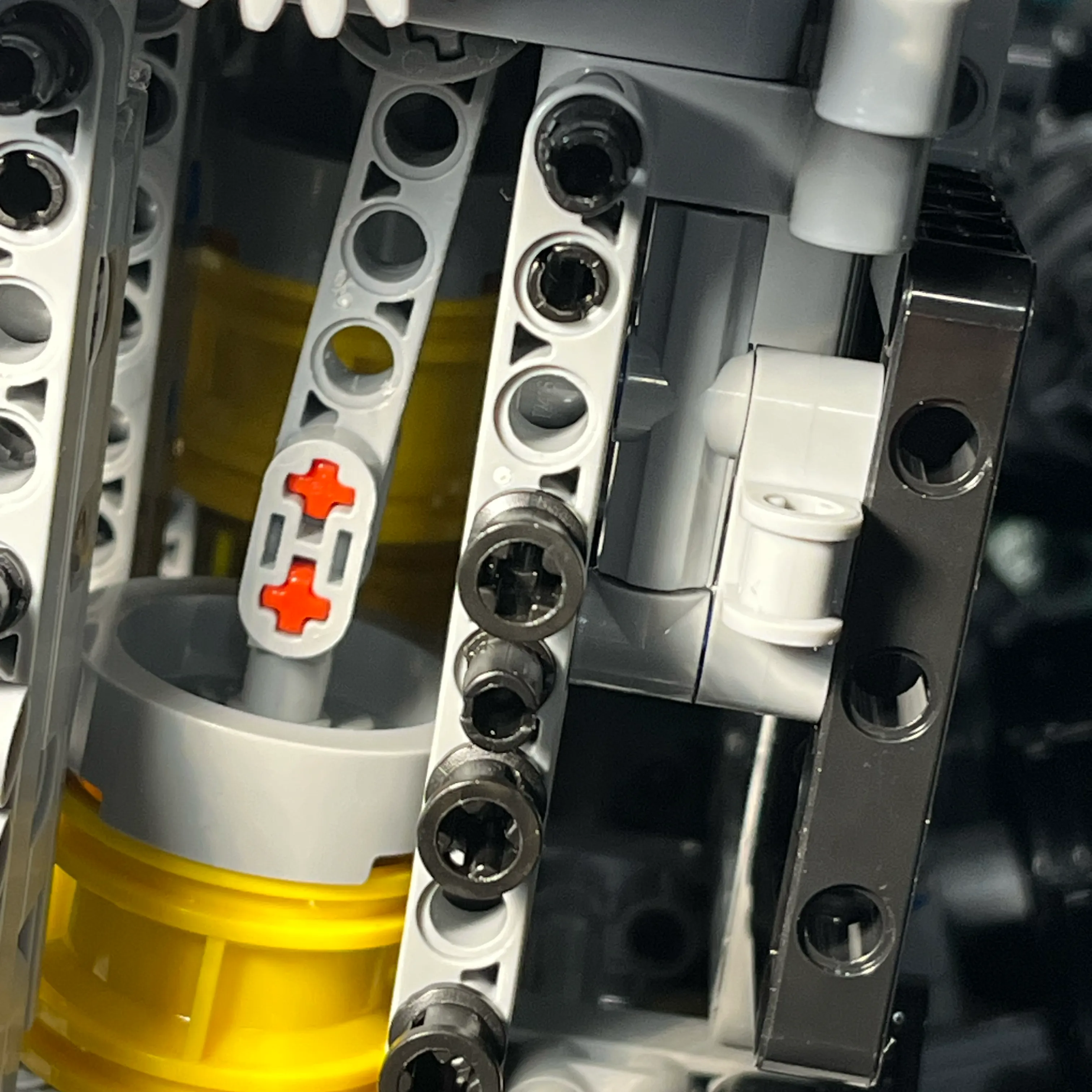
Up close view of upside down engine, moving piston up to meet connecting rod
Up close view of upside down engine, piston reattached to connecting rod
Cam Drive System
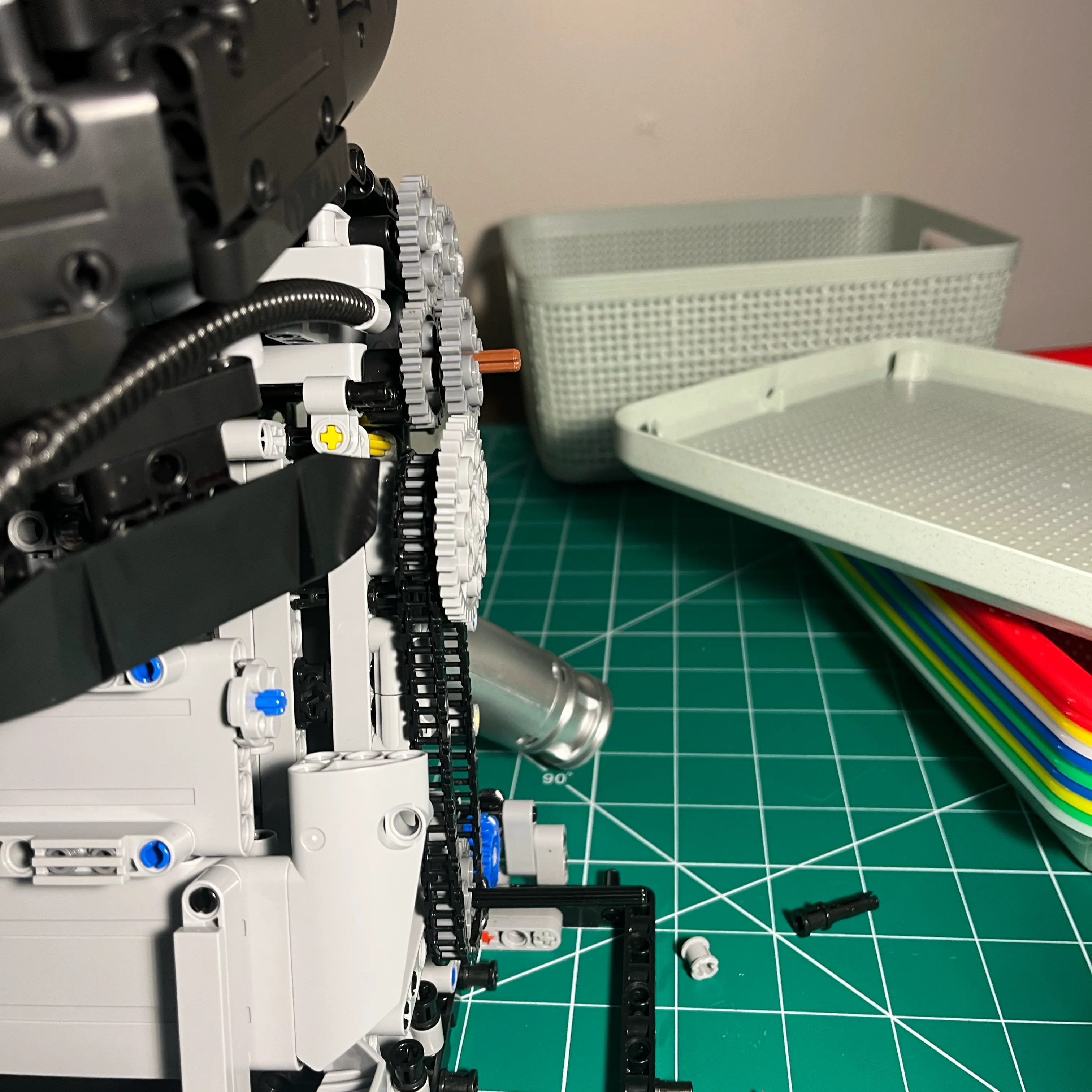
The stock cam drive system utilizes two chains. While it looks incredible.
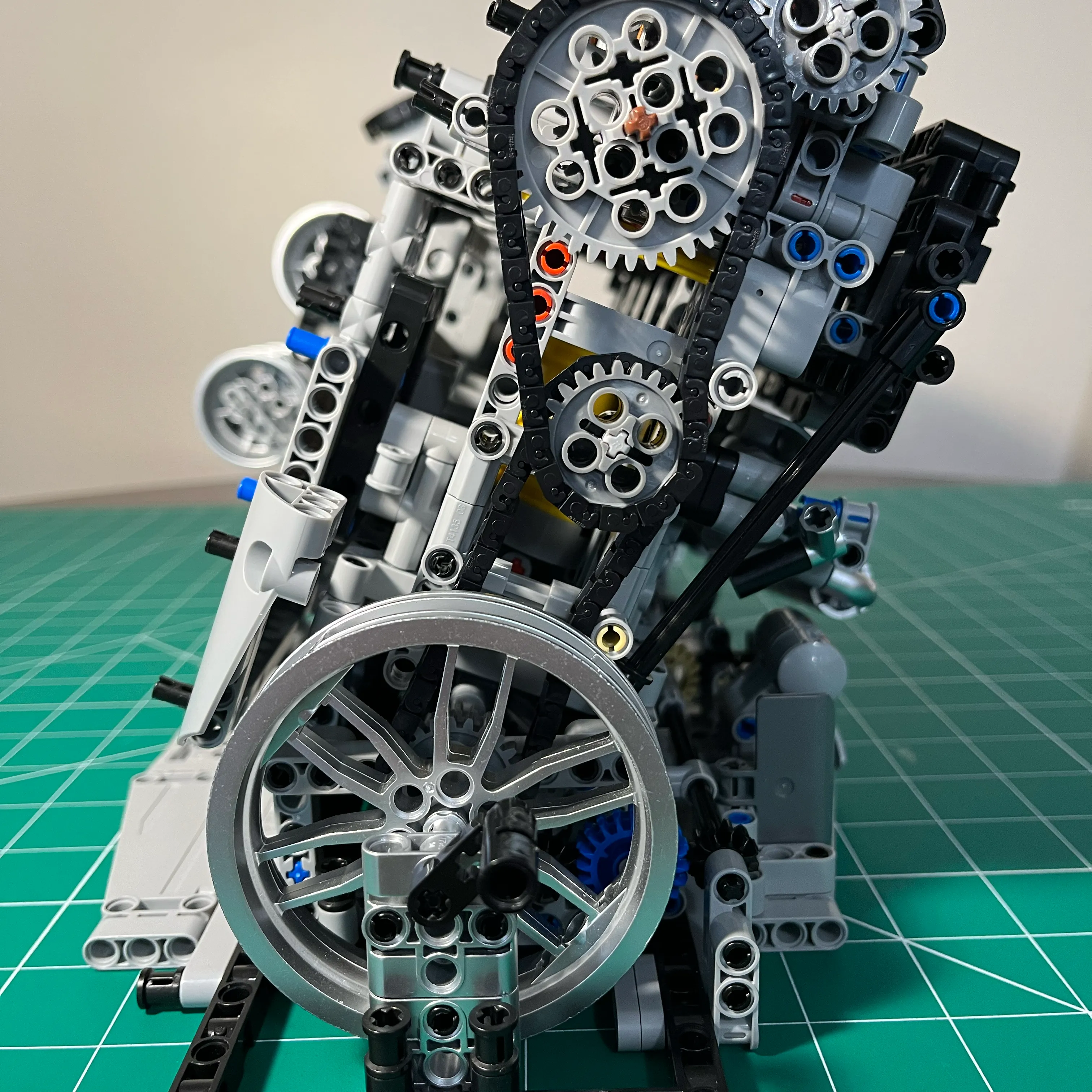
Due to binding issues in the stock build, the amount of torque required to turn over the engine is more than the stock cam drive system can handle. Tightening the cam drive system involves removing links from the chains to shorten them. I axels that hold the idler gears aren’t designed to withstand shortening of the chains. The added tension pulls the idler pin downward, causing the gears to lose contact with the left camshaft.
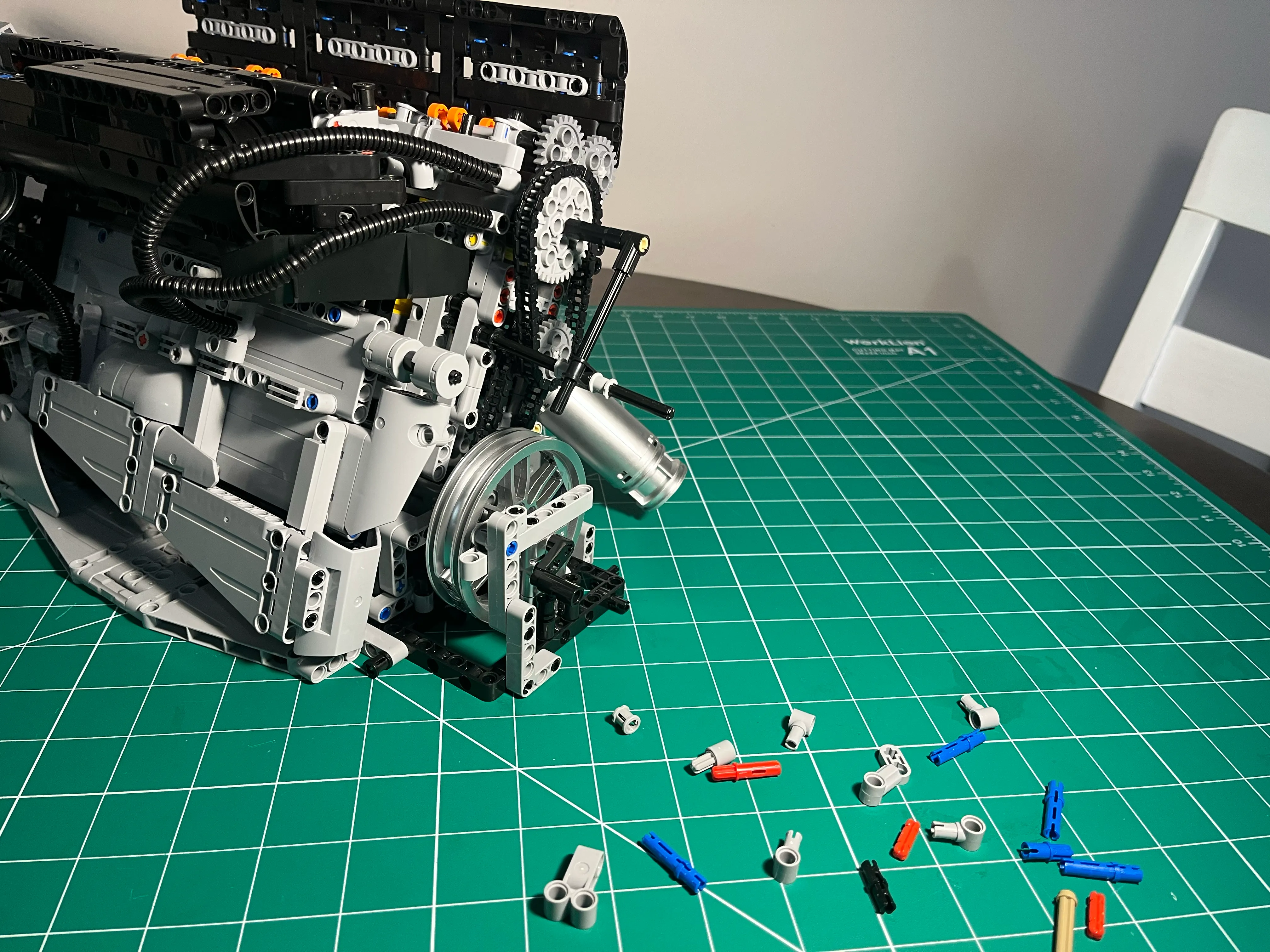
Redesign and Testing
To solve this, I used some additional Technic-style parts to completely rebuild the cam drive into a fully gear-driven system, eliminating the chains entirely. I’ve since tested the durability of this redesign using a cordless drill to ensure the timing and clearance hold up under stress.
My next step is exploring a Technic motor integration, specifically looking for a motor with an RPM range that respects the friction limits of the plastic components.
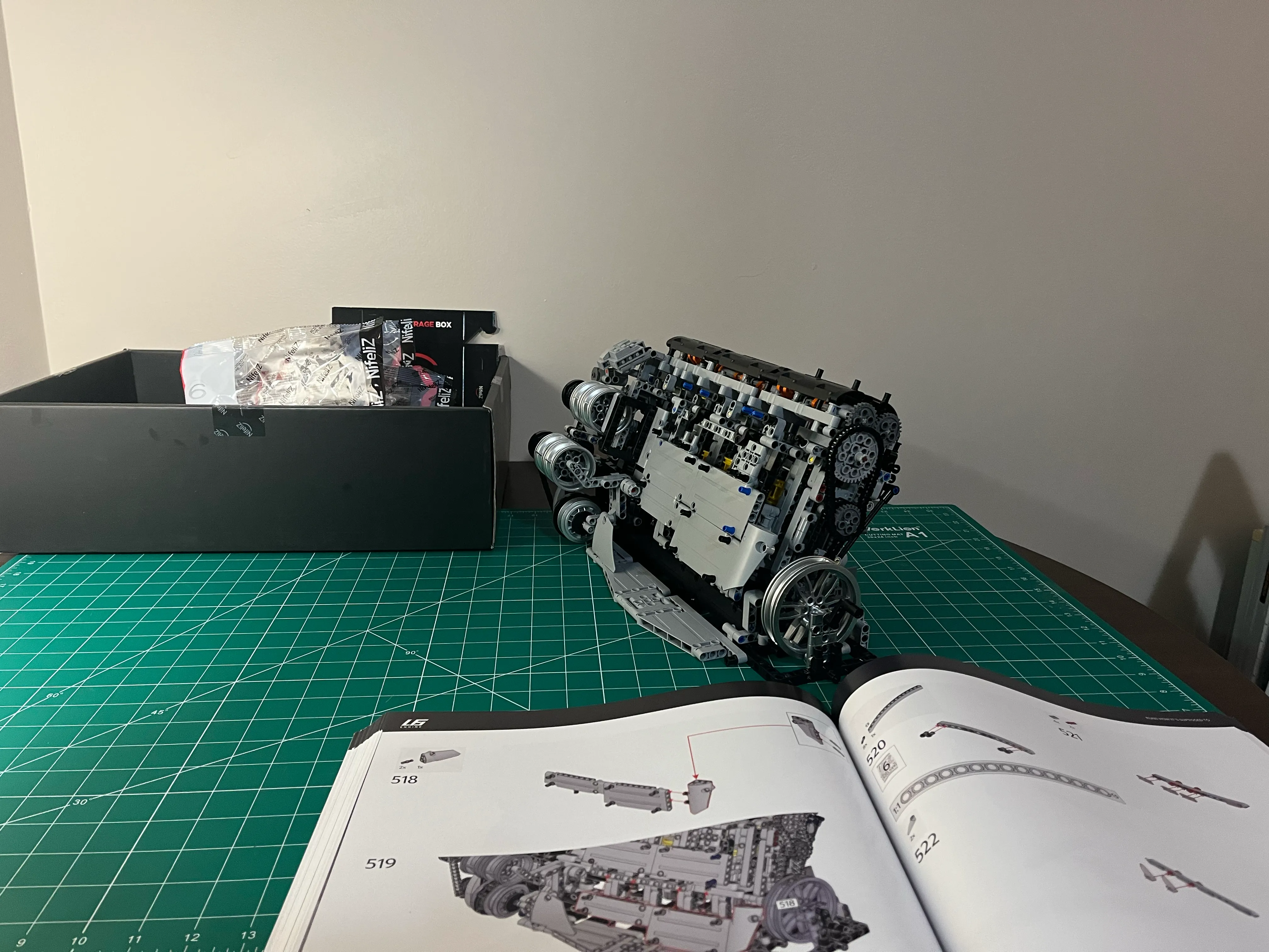
Full Build Log: To see a chronological, bag-by-bag visual walkthrough of the entire assembly, check out my post NifeliZ L6 Photos.
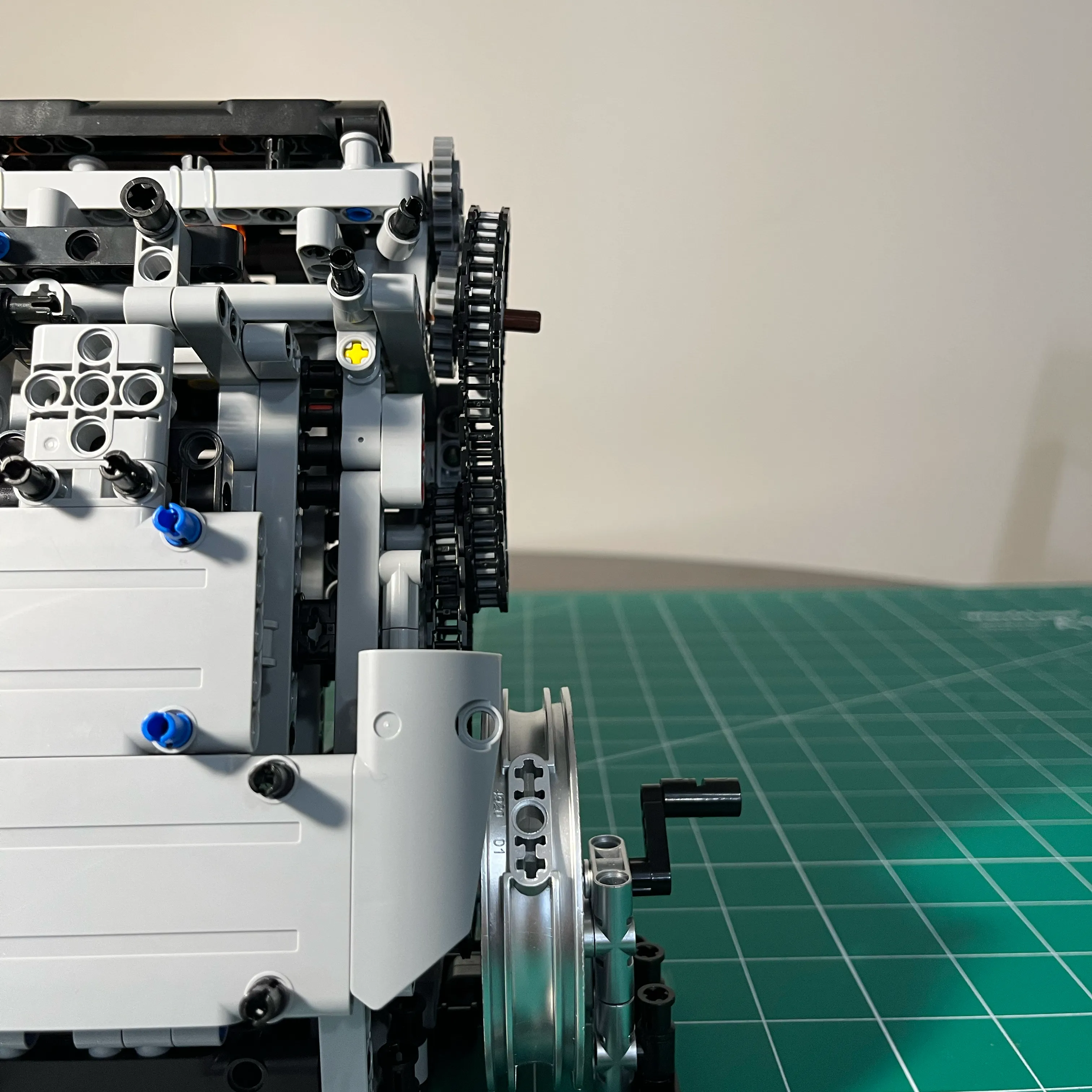
Front View
Side View
The original, flawed chain-drive configuration from the manual.
If I put this engine on display, people are going to want to turn it over, and it’s not acceptable if the chains come apart immediately. The structure at the back of the engine simply wasn’t sturdy enough to keep the assemblies in alignment.
Exoskeleton Design Experiment
To try to eliminate flex, I first experimented with using the engine brace as an exoskeleton to hold the gears in a fixed position.
Here’s a few pics I took while I did a small structural change to implement the exoskeleton. What a monster. lol.
This worked better than I expected. If it works, is it really a dumb idea? lol. I couldn’t leave it like this.
Replace One Chain With Gears
The plastic chains that come with this model engine simply aren’t strong enough to hold up to the torque needed to spin the engine when perfectly aligned.
I experimented with converting both chains that drive the cam gears with a gear driven assembly. There were not enough parts in the kit to replace both chains. However, there were enough parts to replace the upper chain with gears.
Here’s what it looked like after I replaced the upper chain with gears.
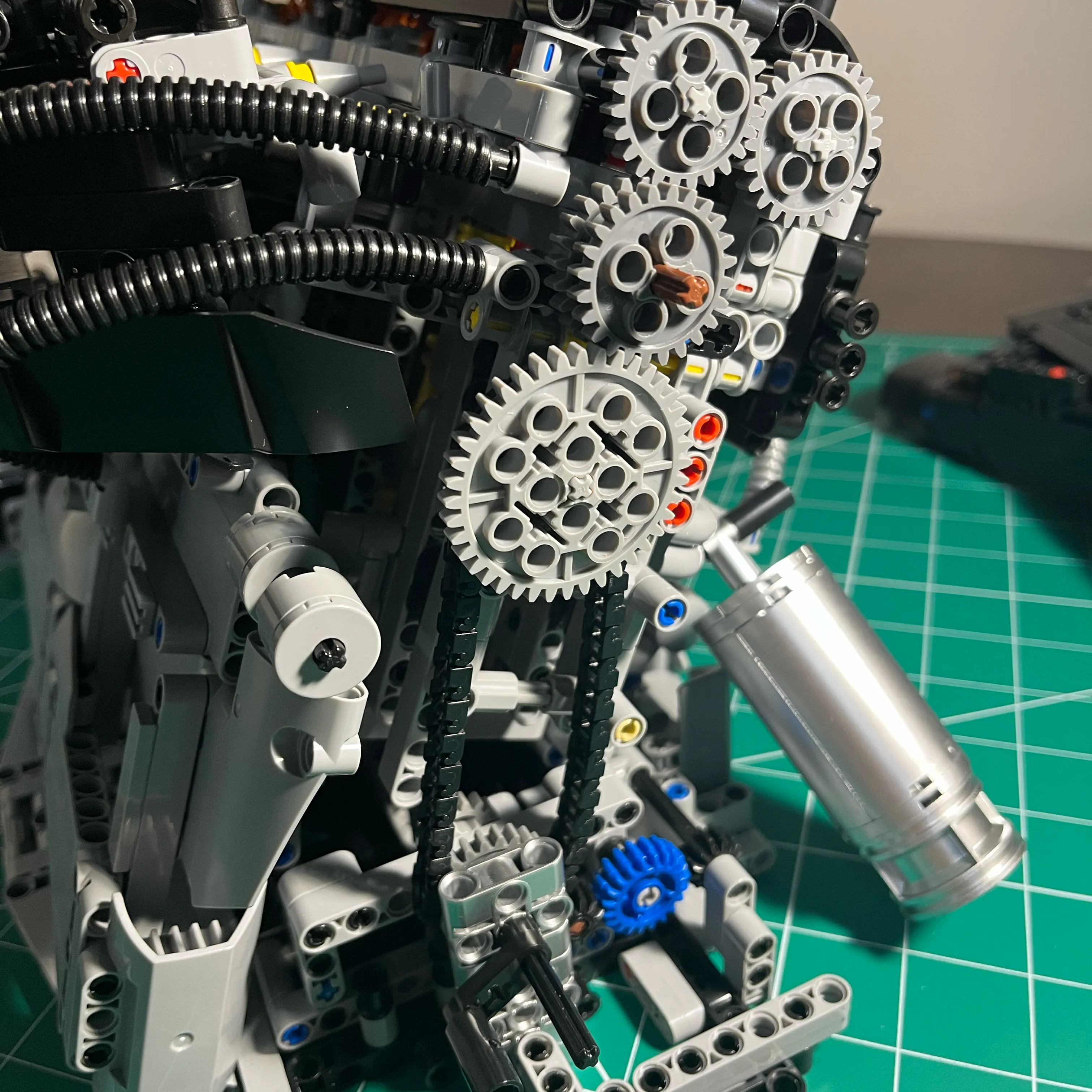
This worked really well. This was enough to resolve the bulk of the flex issues in the cam gear drive assembly. I could have stopped there.
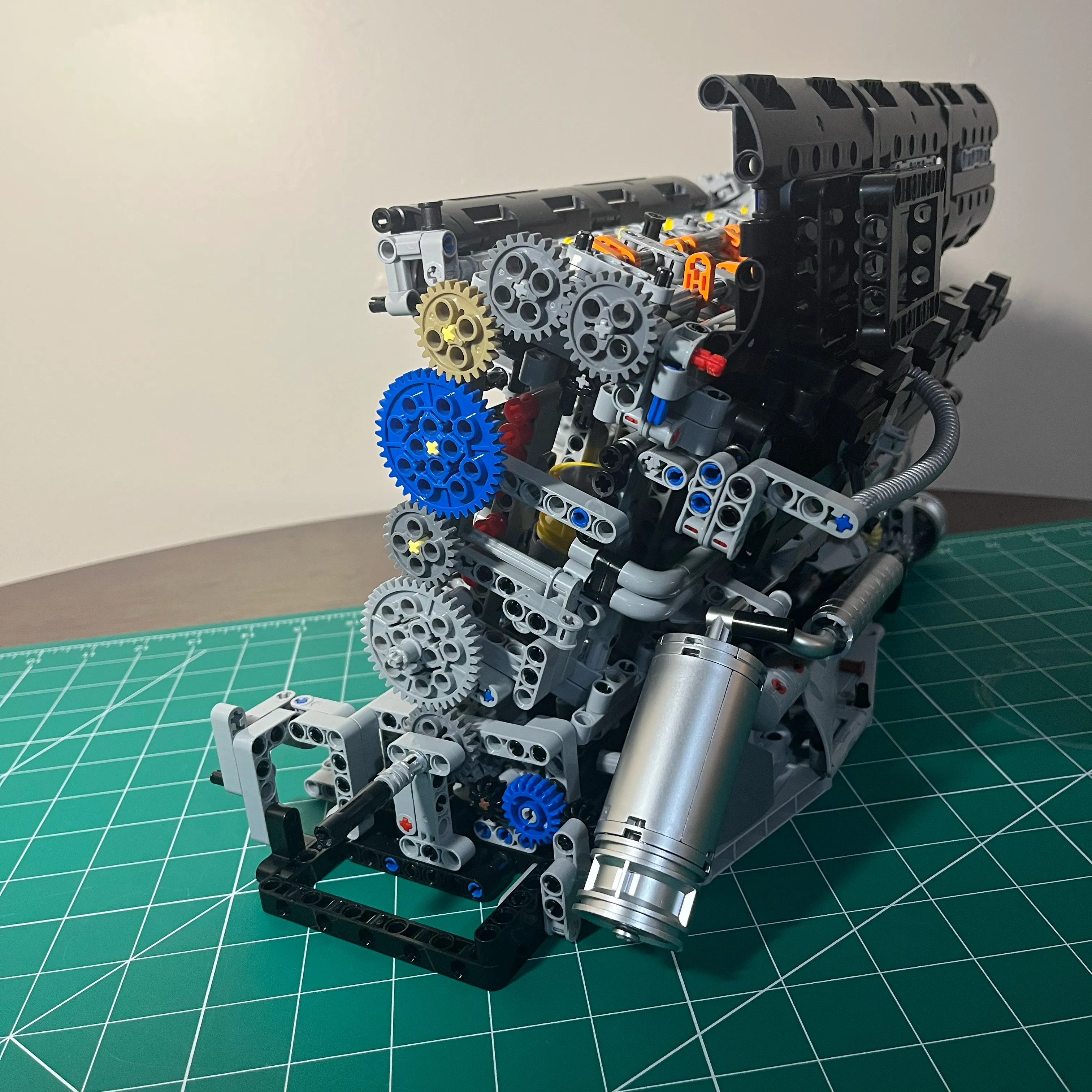
Fully Gear Driven Cam Drive
To replace both chains in the cam drive assembly, I needed to order some bricks. Since the Lego patent is now expired, there are plenty of cheap alternatives. I ordered 2 sets to ensure I had enough parts.
- 184PCS Gear and Axle Set for Technic Parts
- 582pcs Technical Parts and Pieces Beams Axles Connectors Bricks Sets
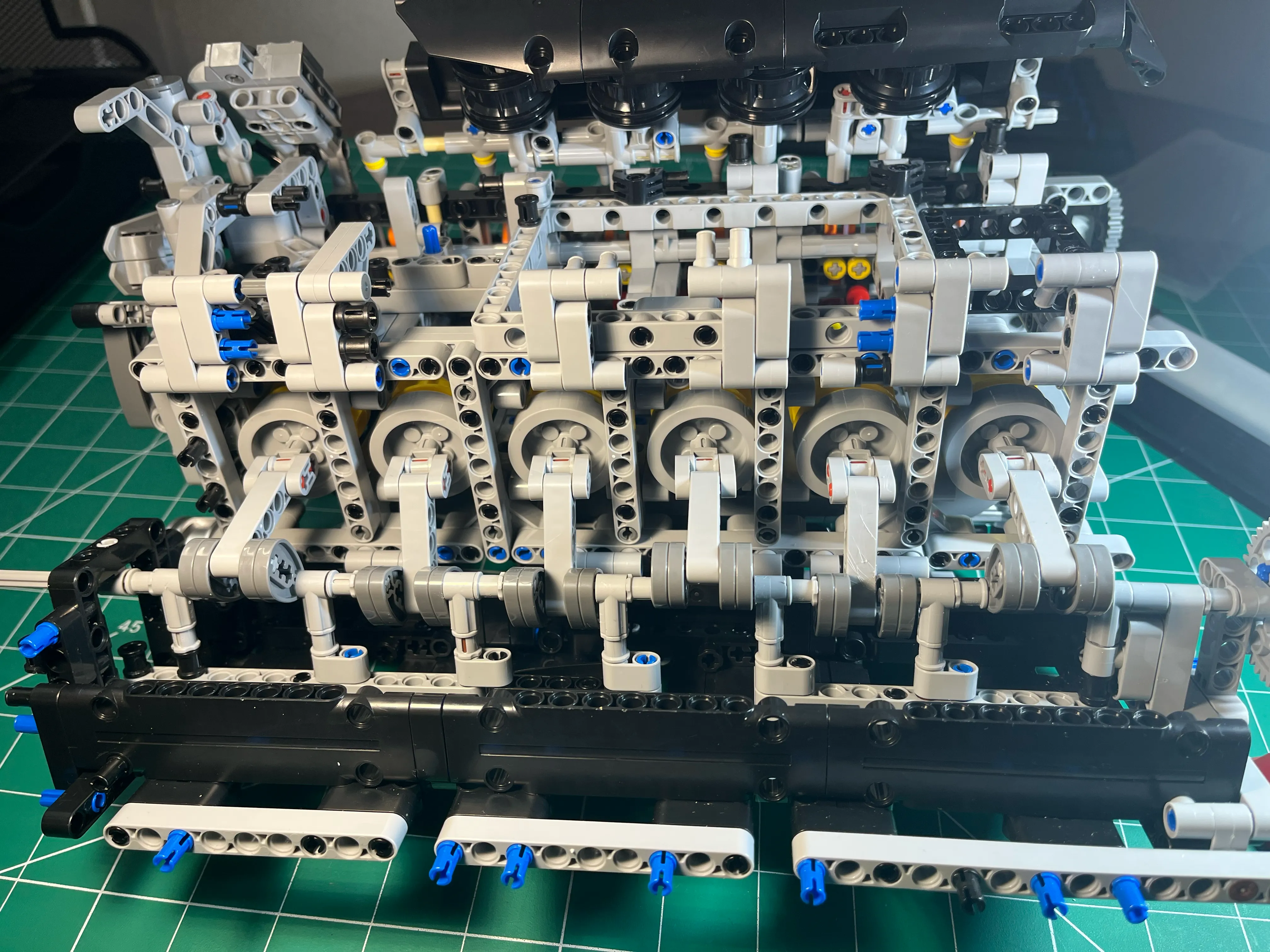
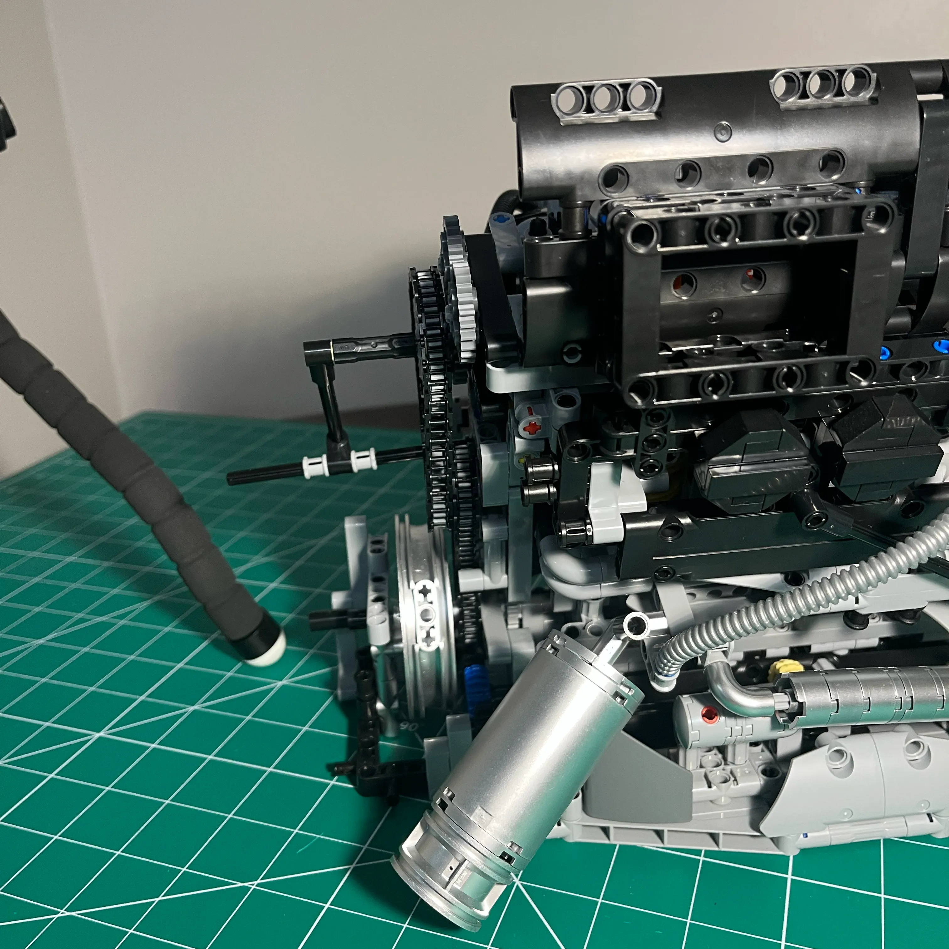
Once those parts showed up, I prototyped a fully gear driven cam drive system. I overdid it with the structural reinforcing to try and reduce flexing / movement while rotating the engine.
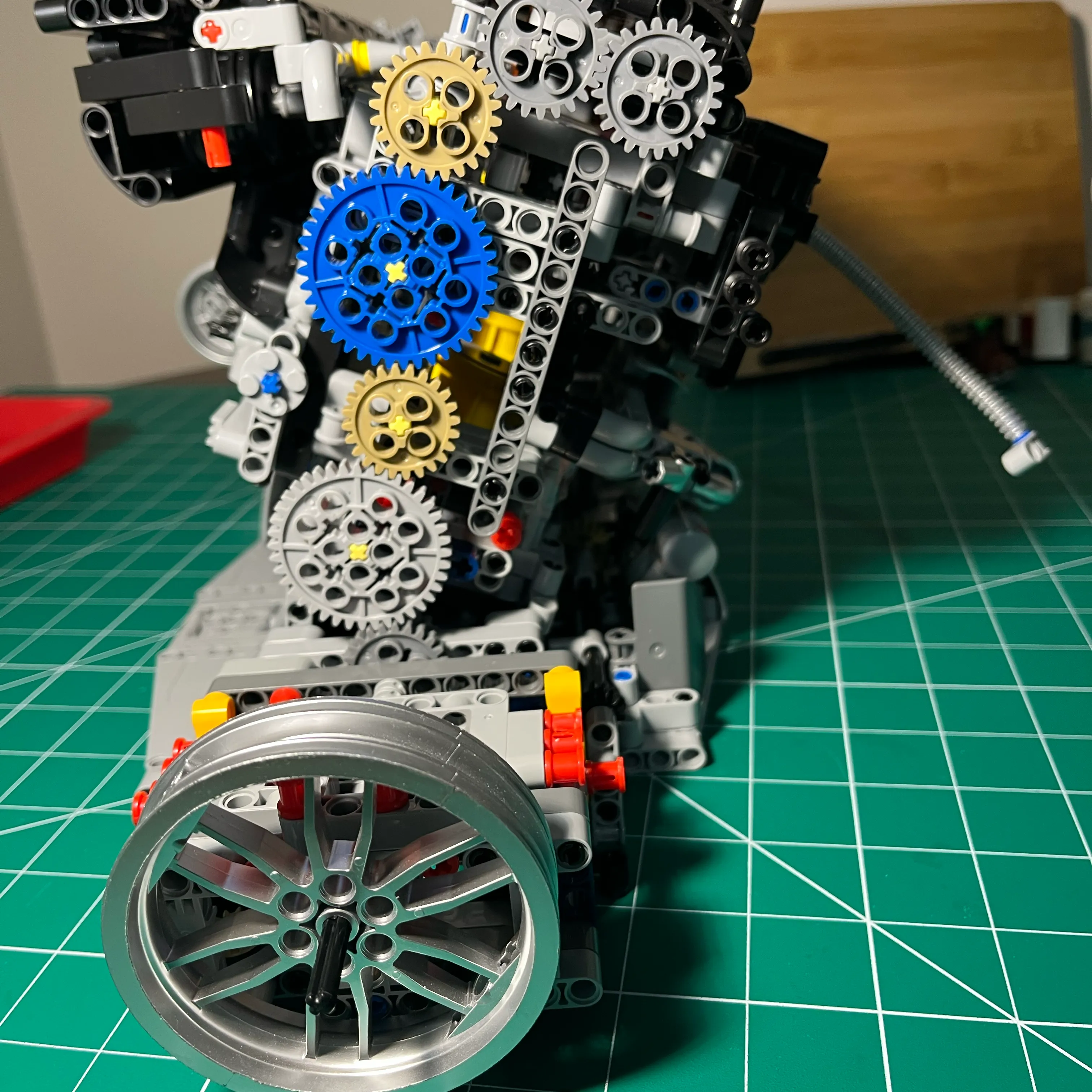
Despite the bulkiness, it worked really well! It worked so well that I tried hooking up a power drill to spin the engine over! That was a lot of fun, until I ran into the binding issue I mentioned previously.
When the binding issue on cylinder 6 happens, the piston often becomes disconnected from the connecting rod. Reconnecting them is a royal P.I.T.A. since there is limited access and visibility. I reattach the piston to the connecting rod by turning the engine upside down (so the connecting rod hangs freely), push the piston up to meet the connecting rod, and using a small screwdriver to push the connecting rod onto the pin on the piston.
I ended up removing the panels on the left side of the engine, to get access to the pistons. I think it looks cooler with the pistons exposed.
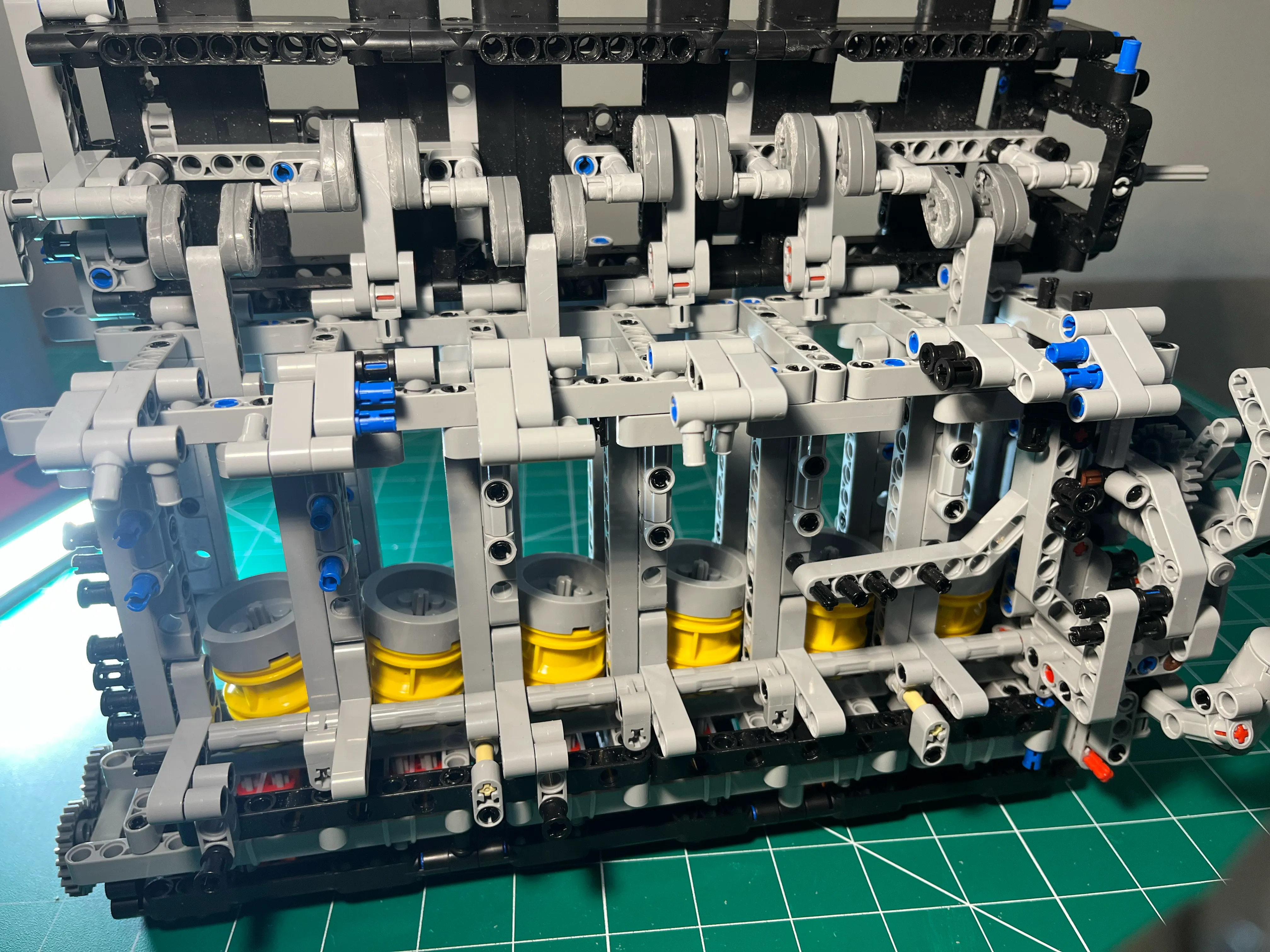
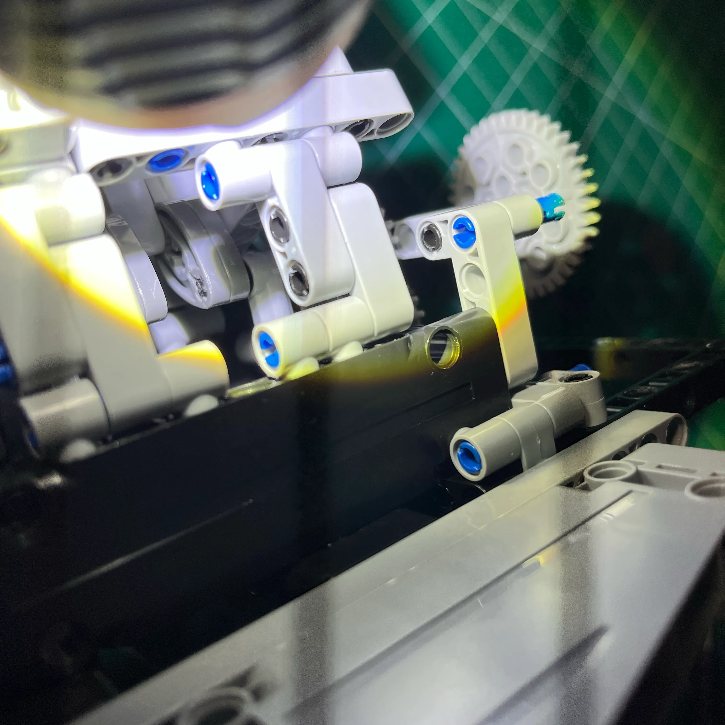
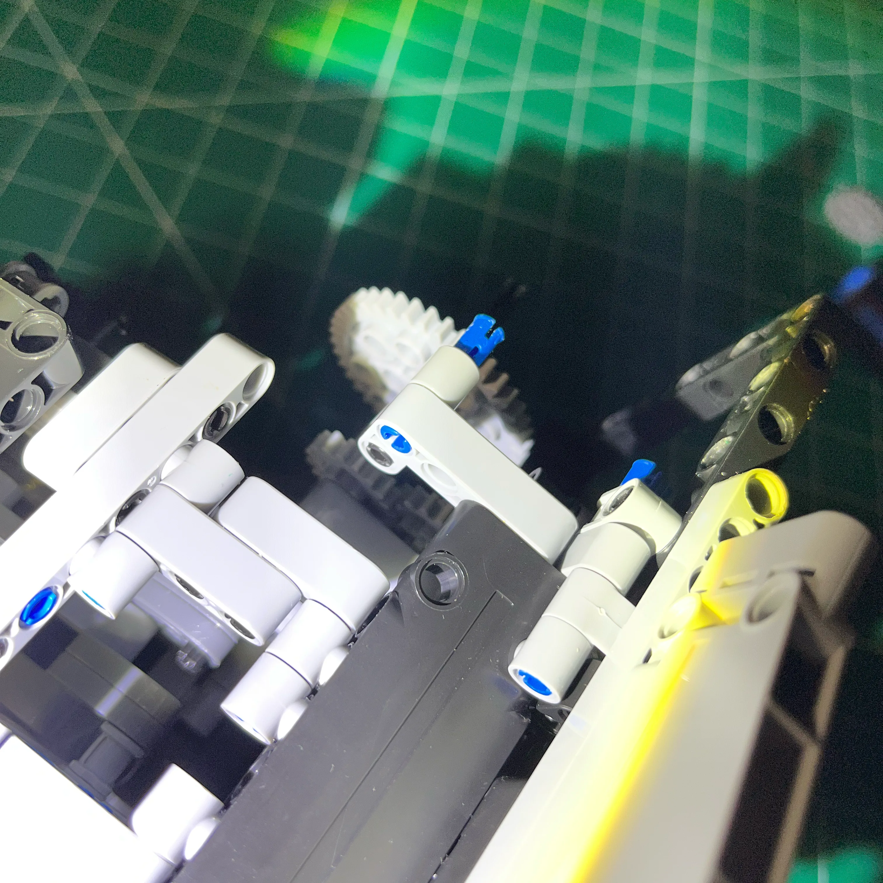
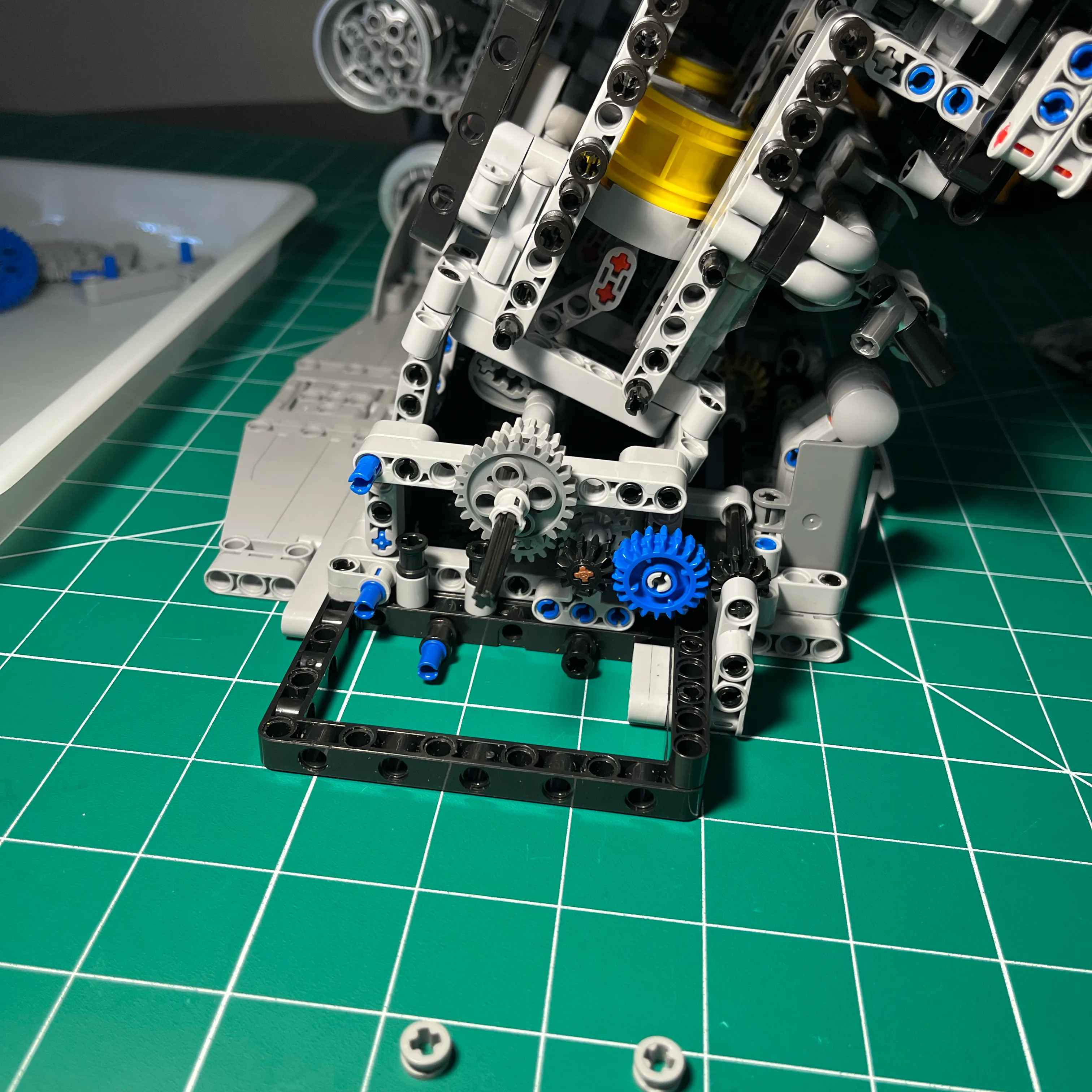
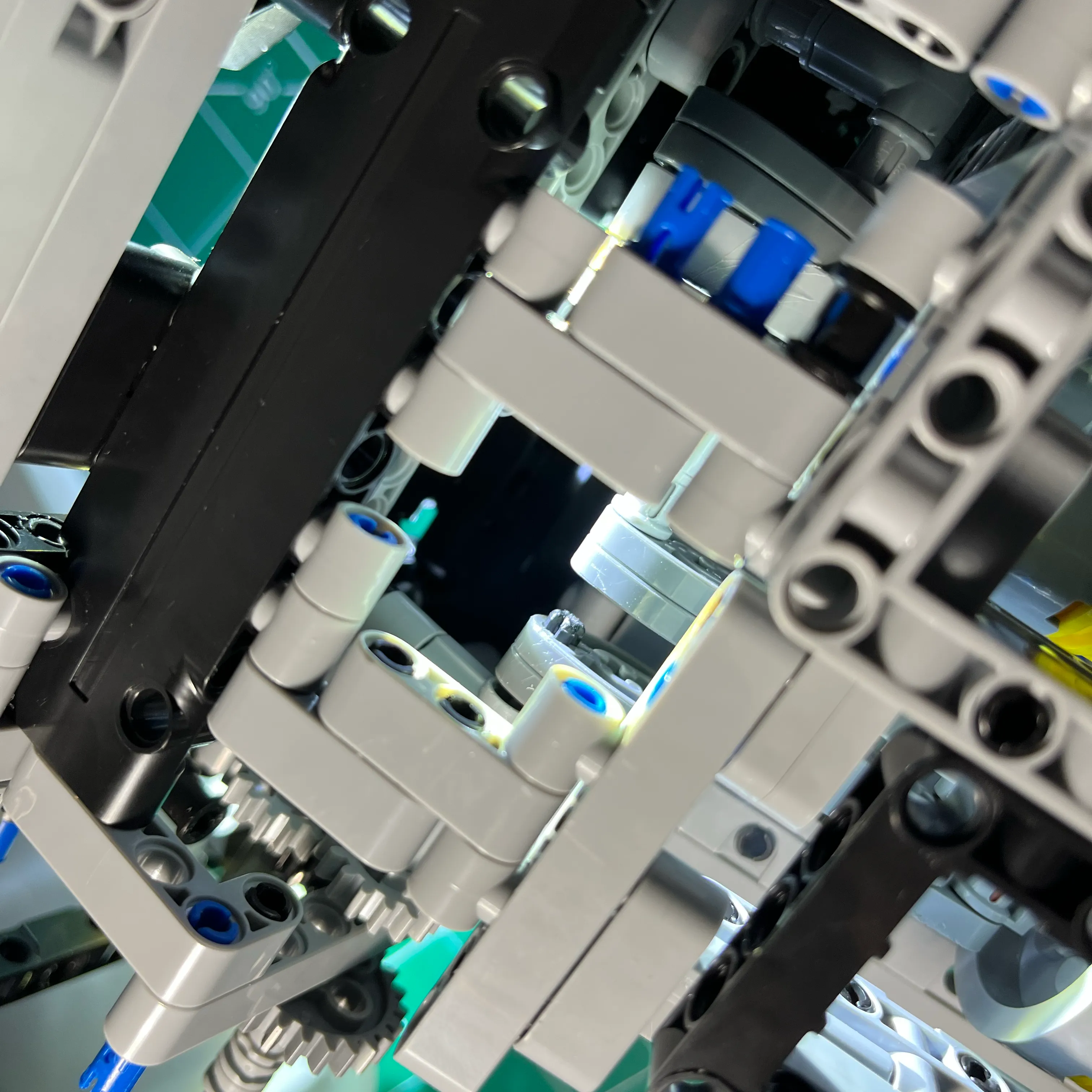
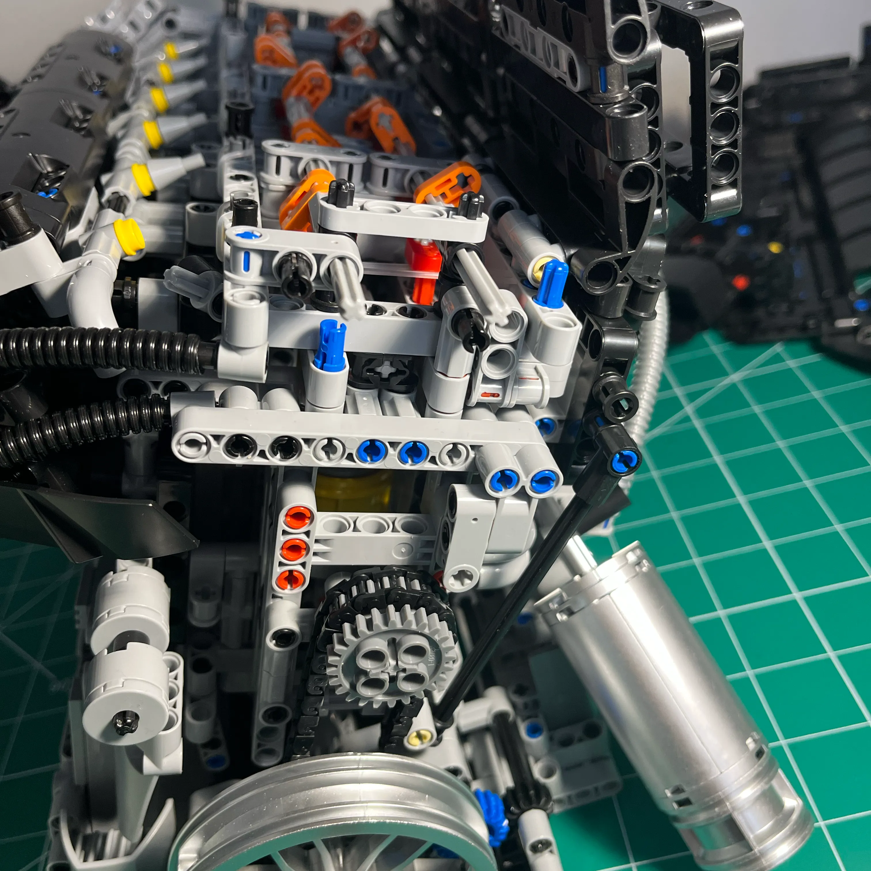
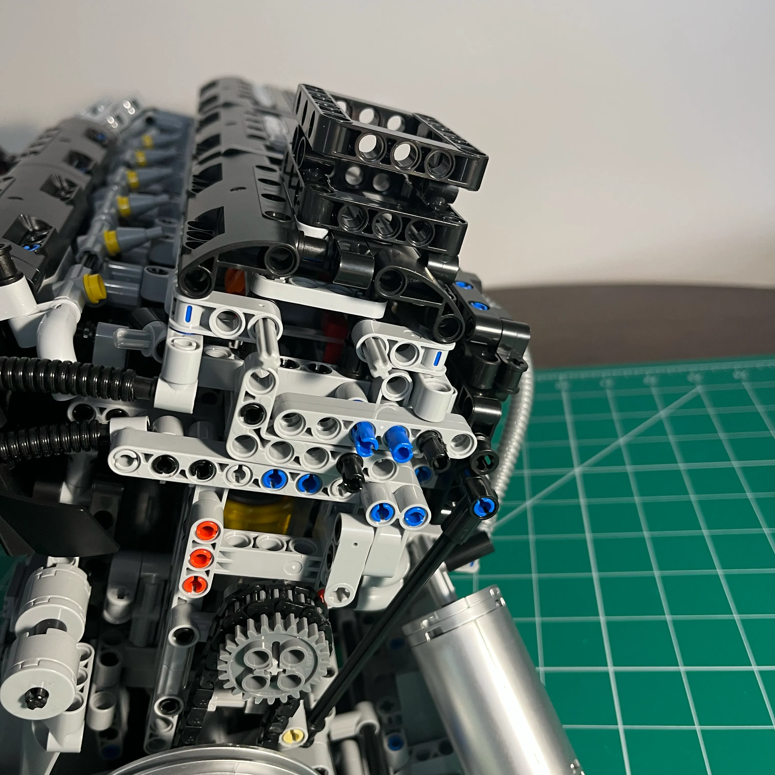
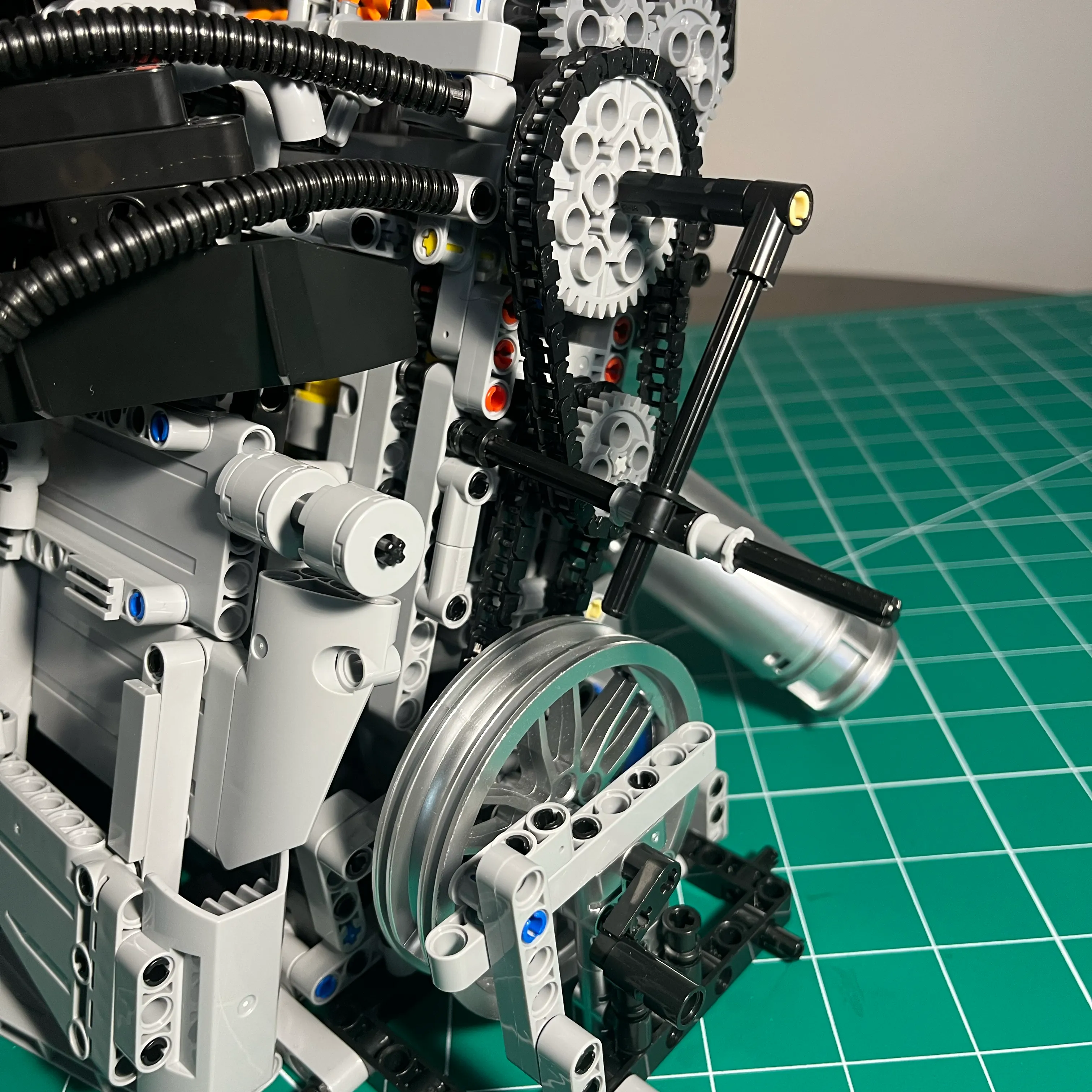
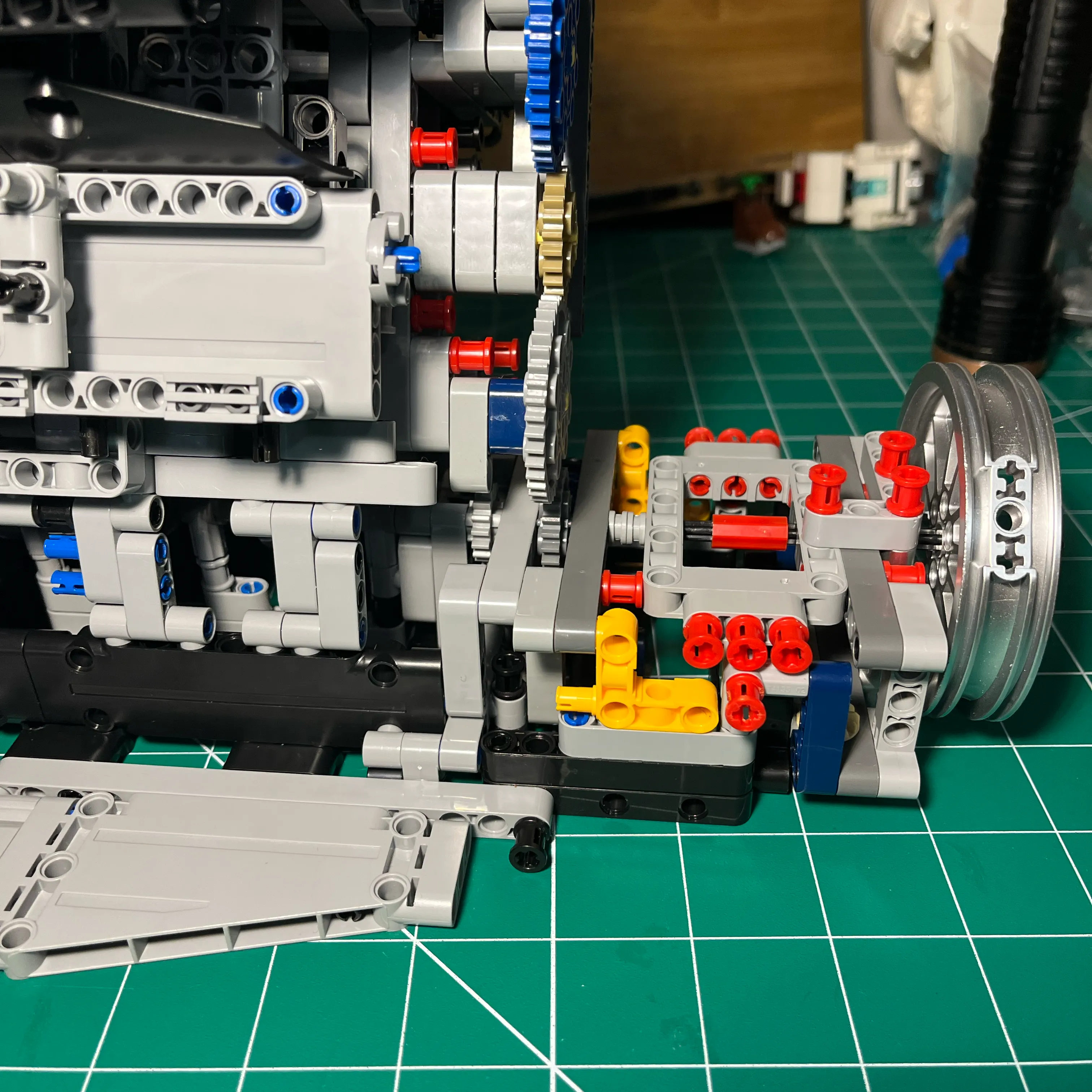
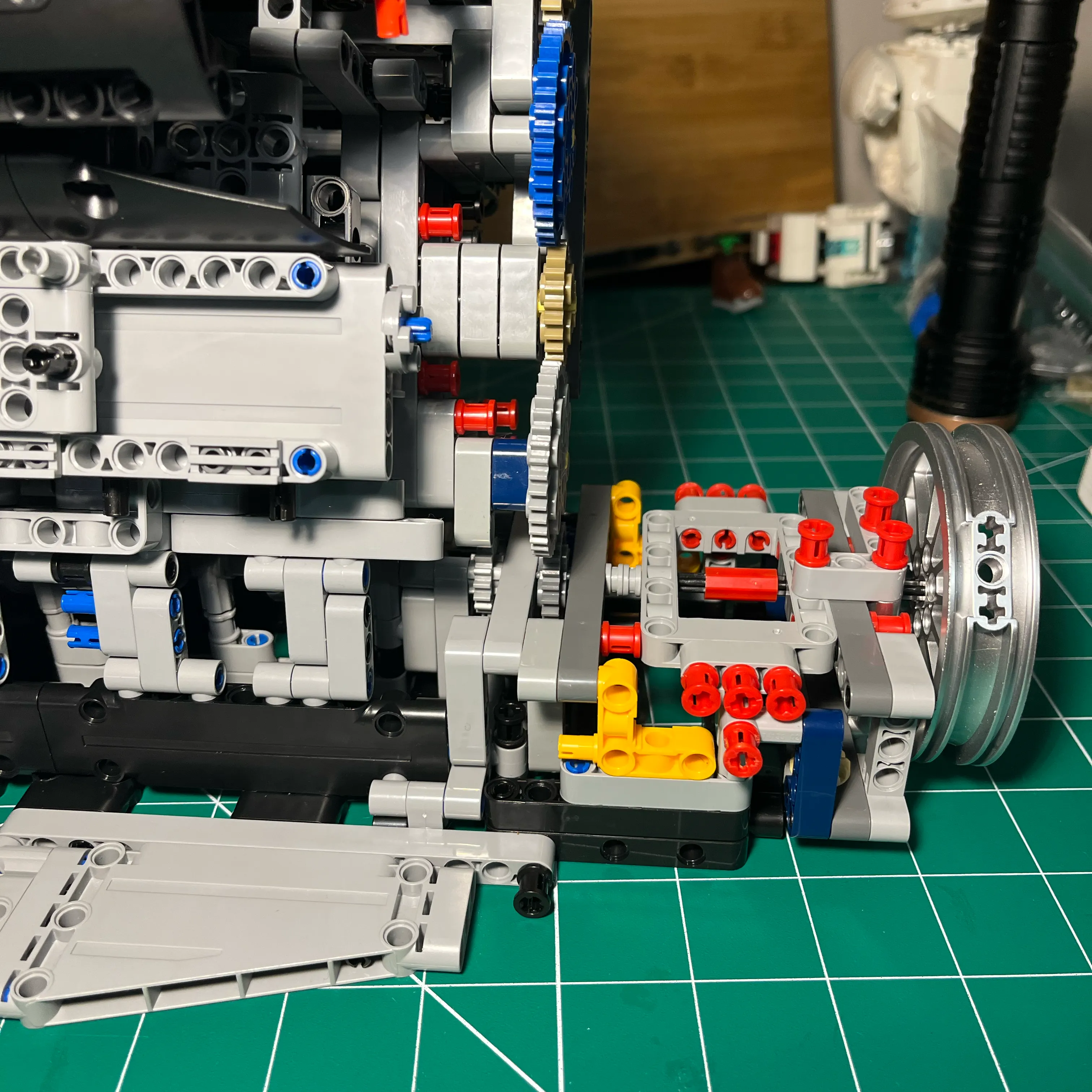
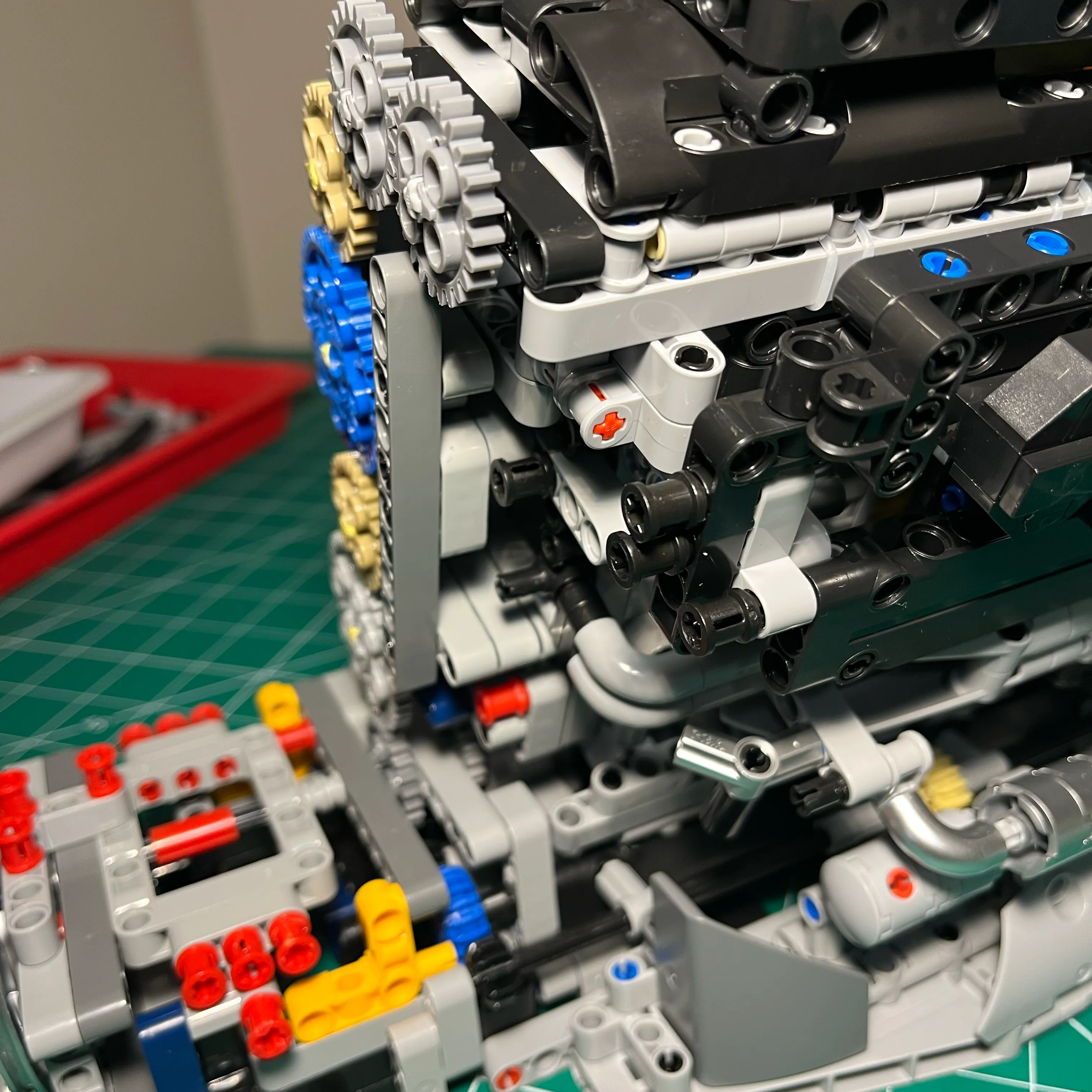
Once I had the binding issues resolved, I went back and removed all the structure I had at the back of the engine, and built a minimal structure. The gear drive requires fewer components, giving a clearer view of the cylinder 6 piston.
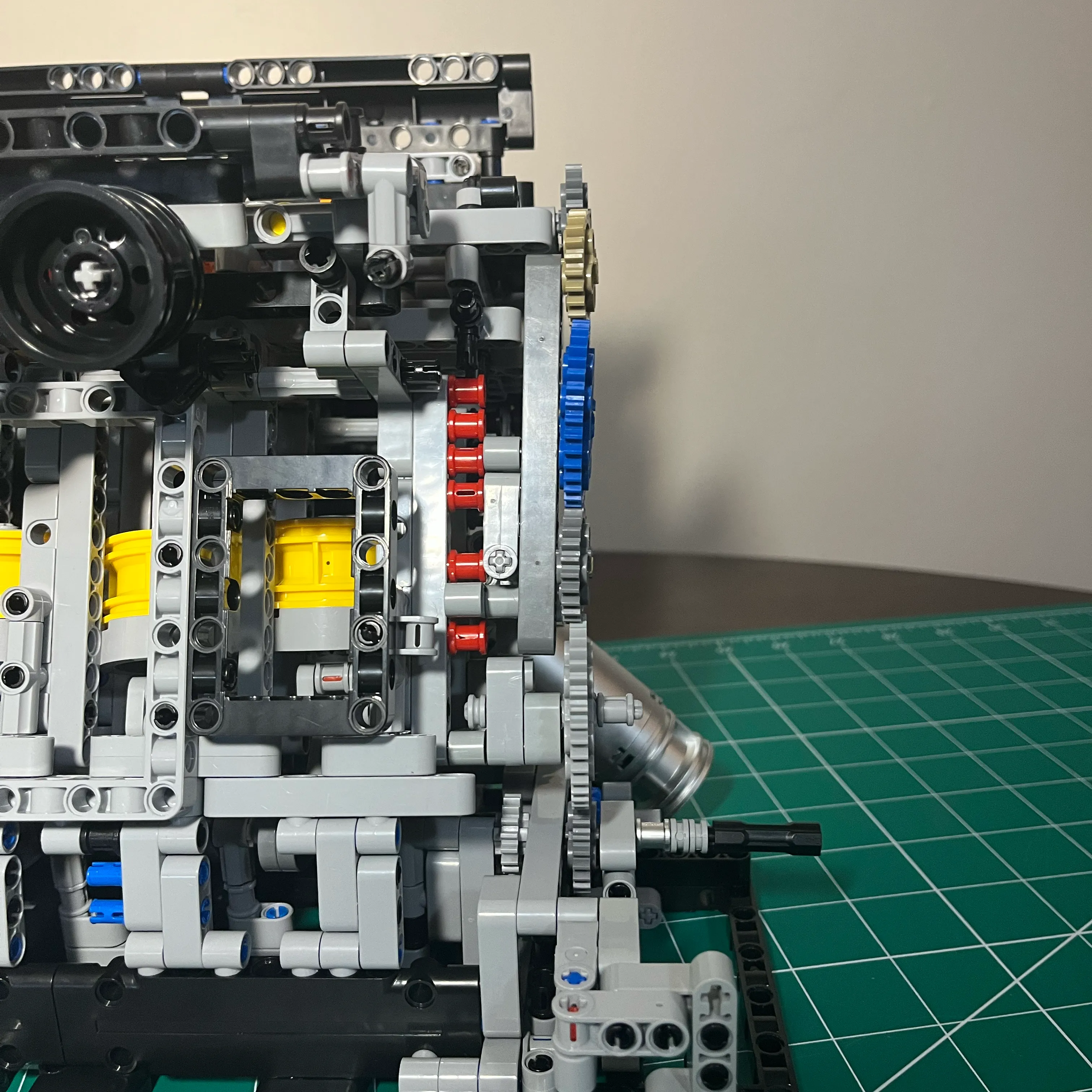
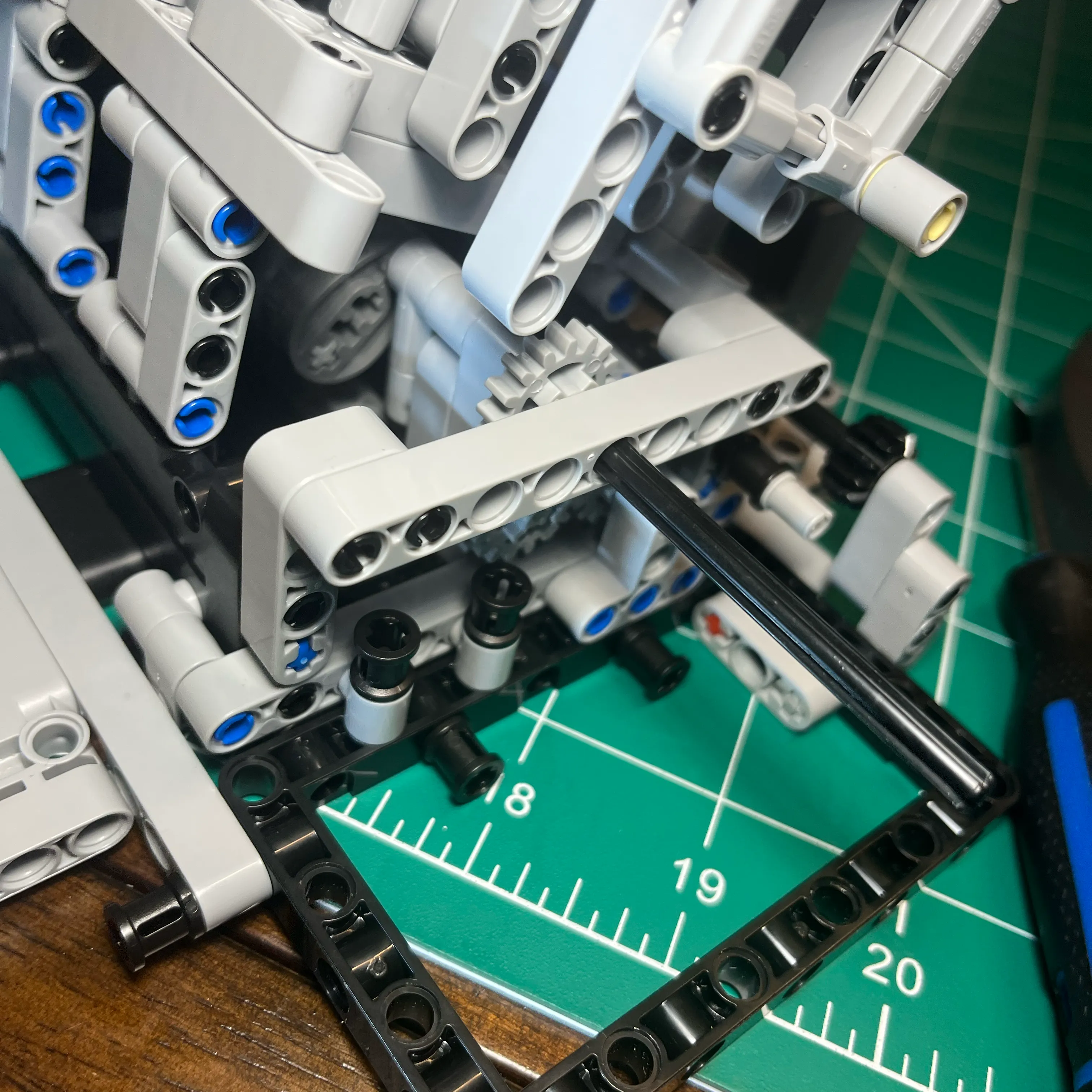
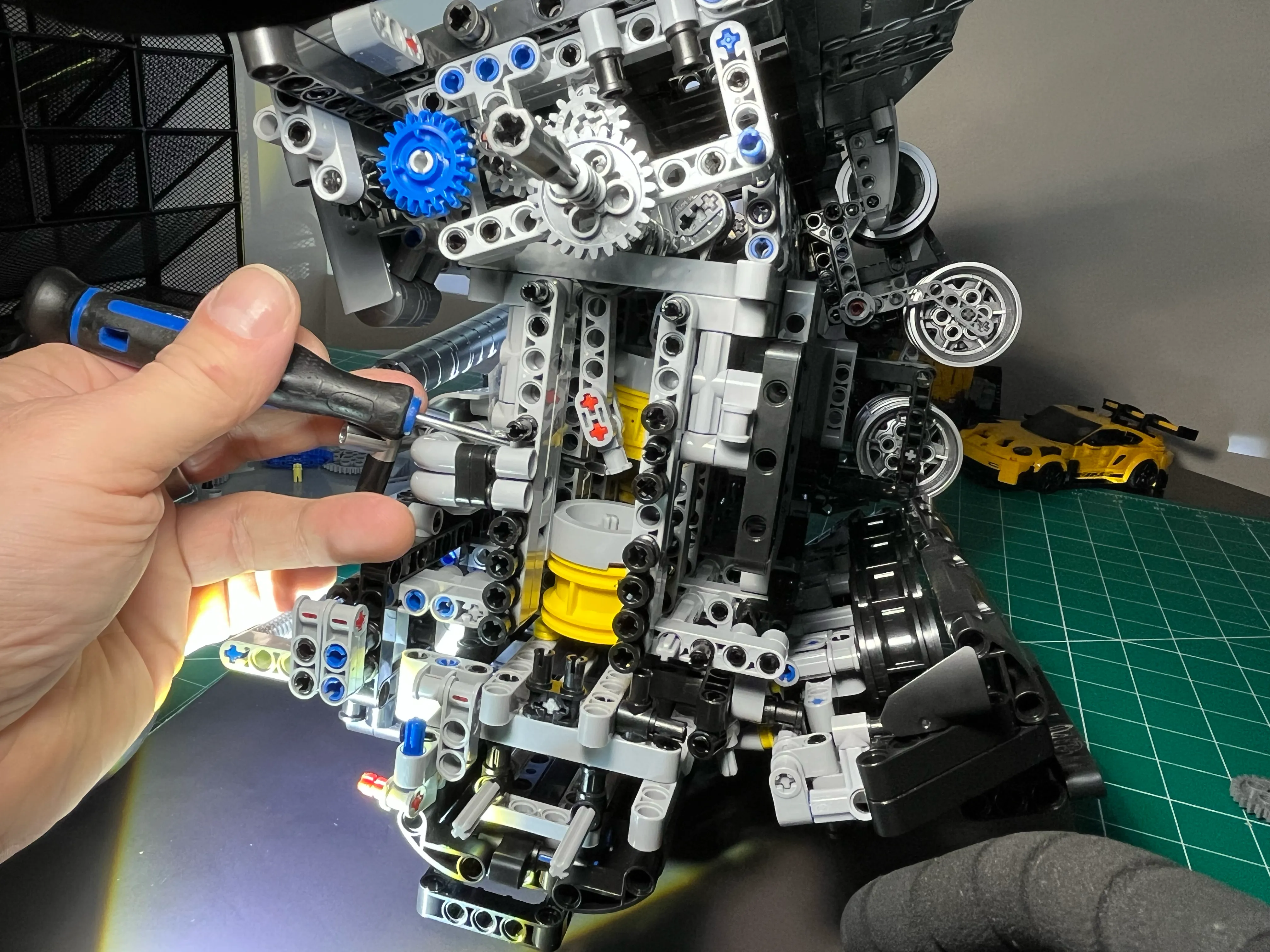
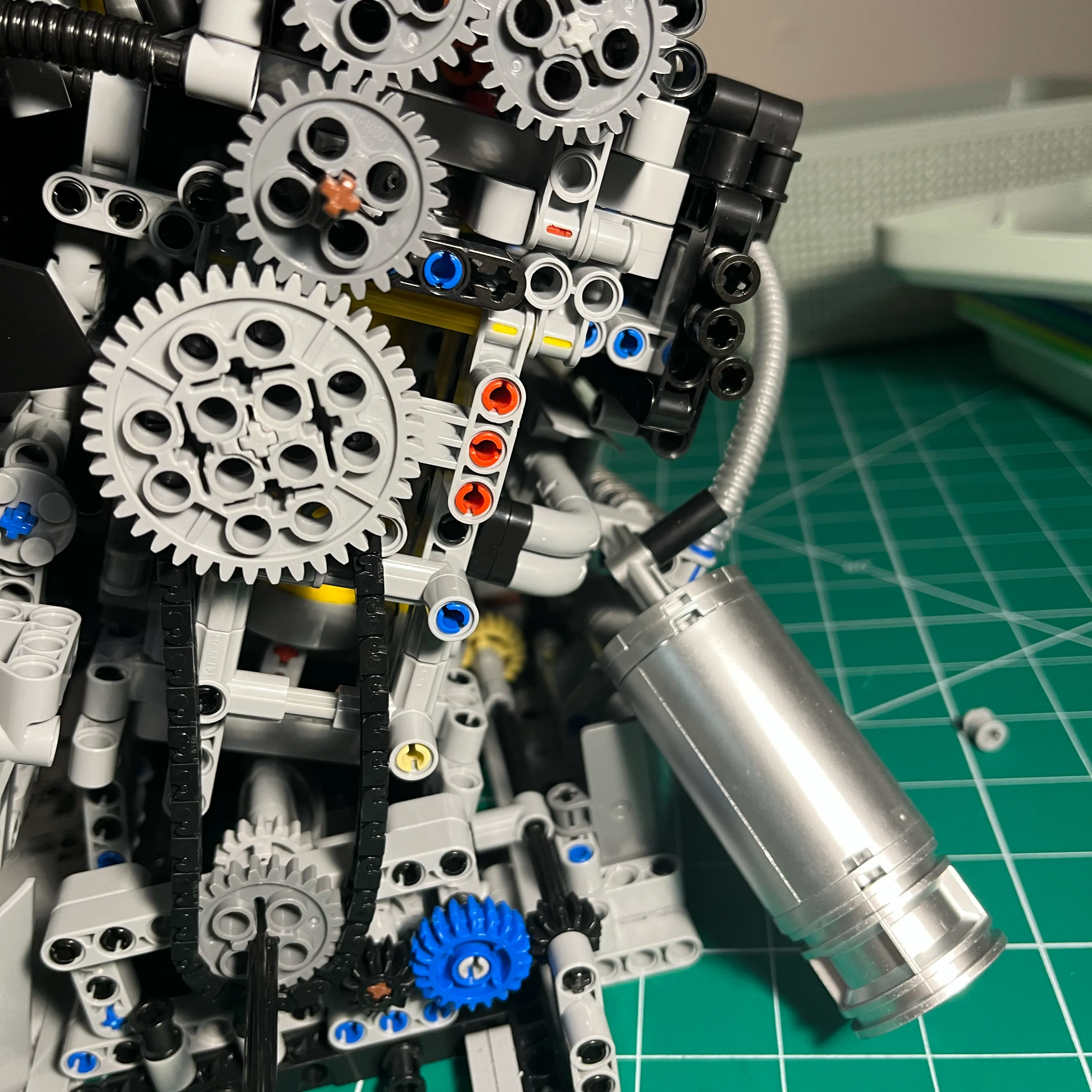
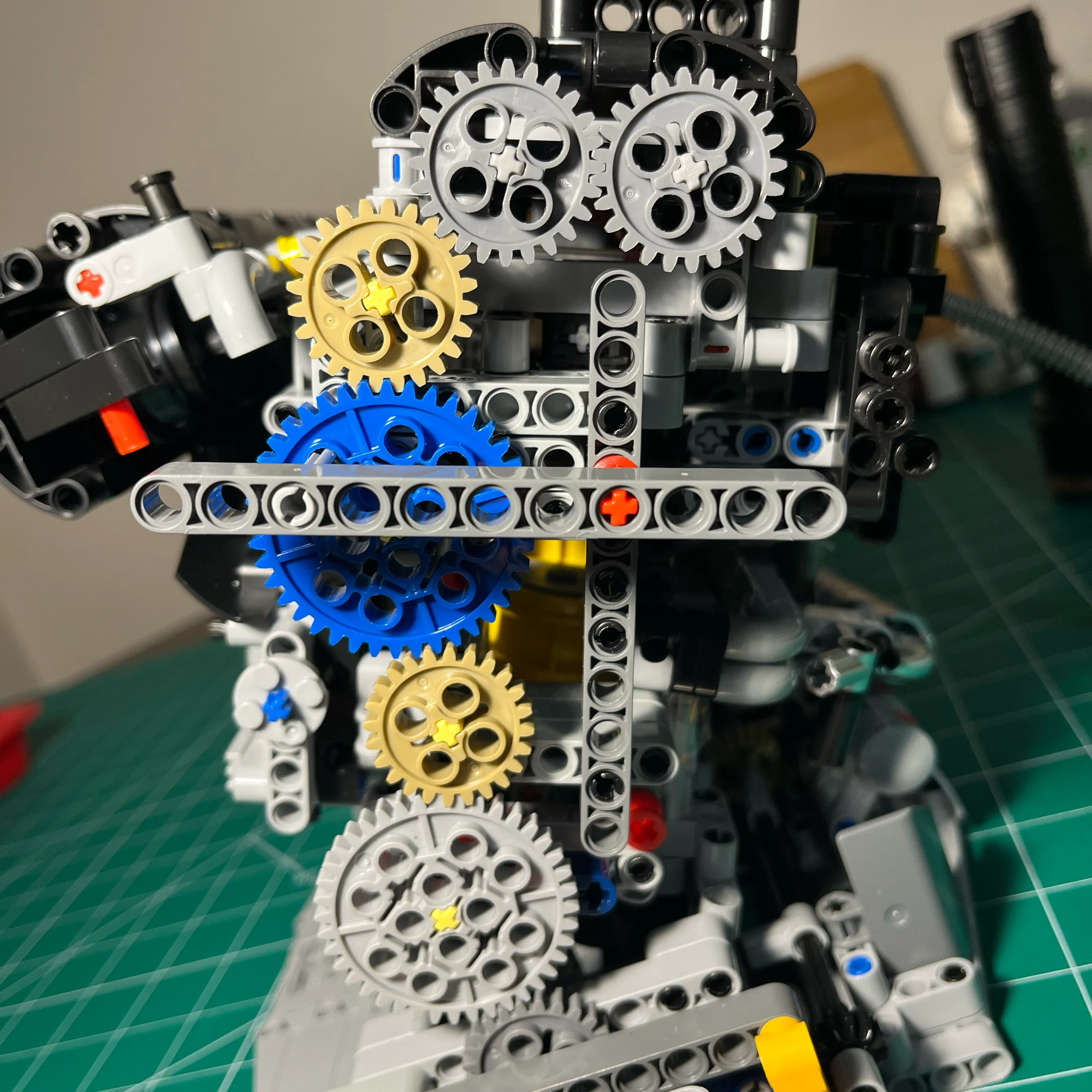
The upper 3 gears are all on one beam, and that beam has a pivot point on the cross brace visible under the large blue gear. I found that there was no sensible way to have a rigid structure that keeps tension on the gears. During mock-up I stumbled upon the pivot idea, by using one pin to experiment with placement. I applied pressure on the beam with one hand, and as I spun the engine over, I saw that it worked!
What I did to apply tension to keep the gears in contact is create a lever perpendicular to the beam holding the 3 upper gears. You can see the lever in the pictures below. Behind the small dark gray gear is a structural cross beam. just above that structural cross beam you can see a gray pin that connects to the gear beam. To get the right amount of tension, I experimented with different pin lengths to attach the other end at. It turns out that attaching the pin on the other side of the structural cross brace so that the pin is horizontal to the cross brace provided enough tension!
Here’s a few pictures of the final version of the fully gear based cam drive system.