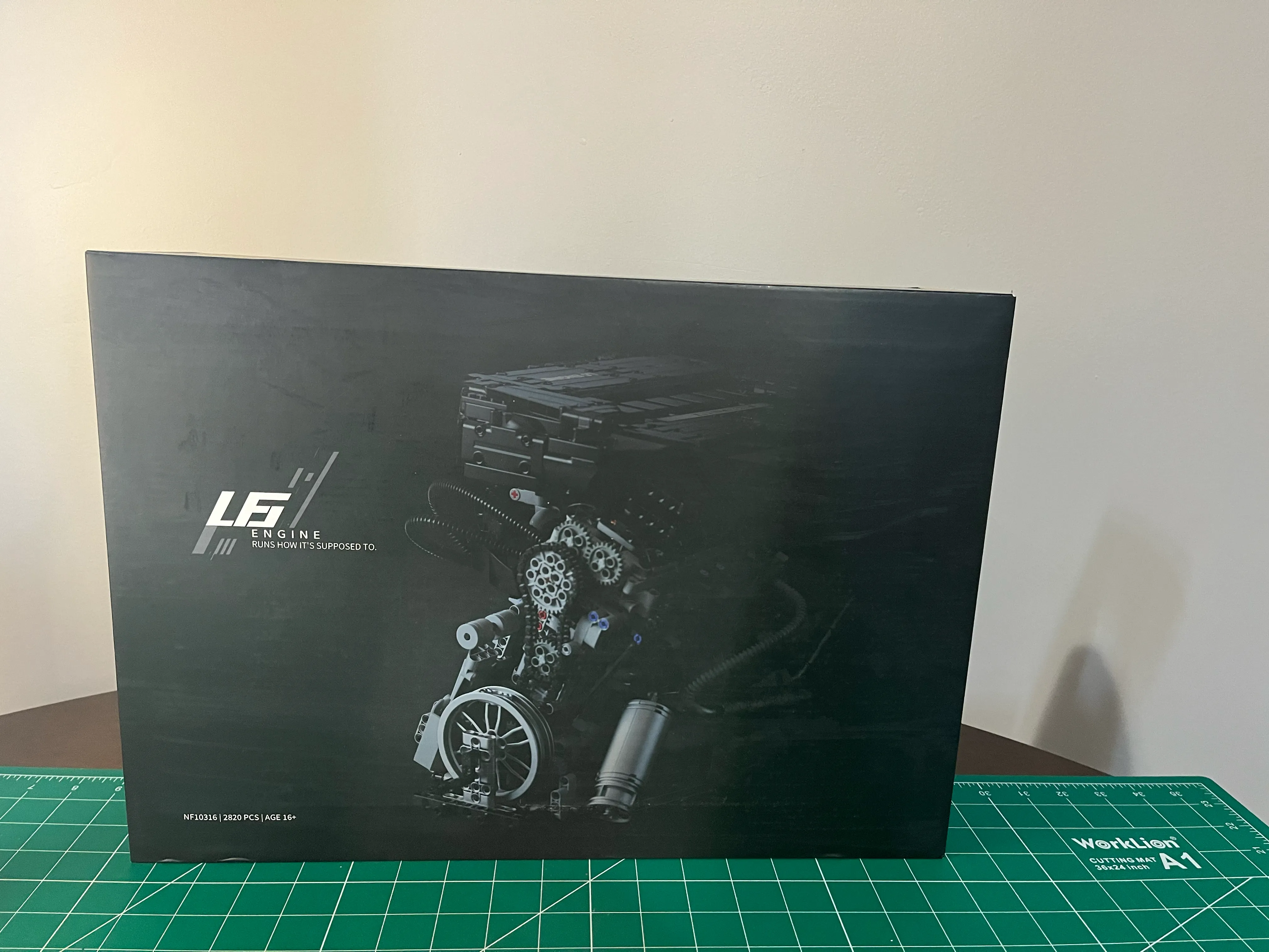
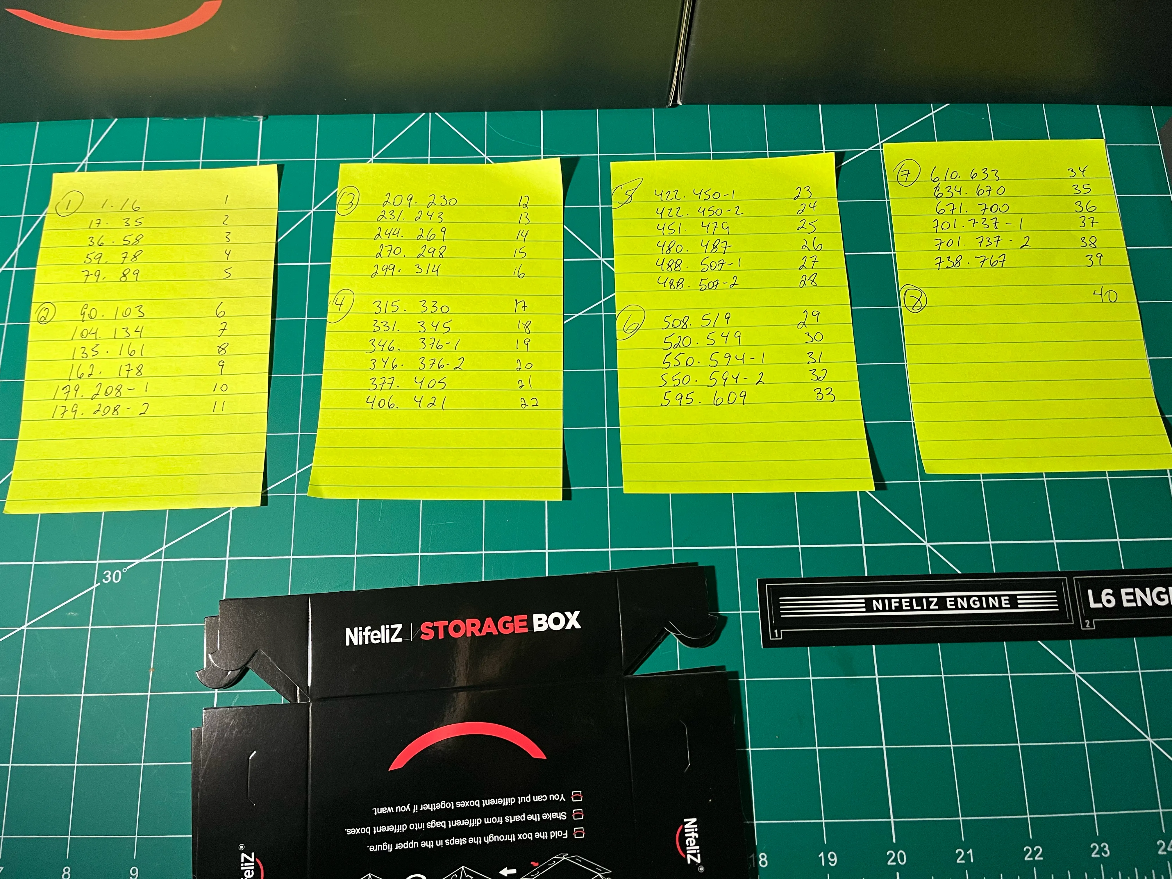
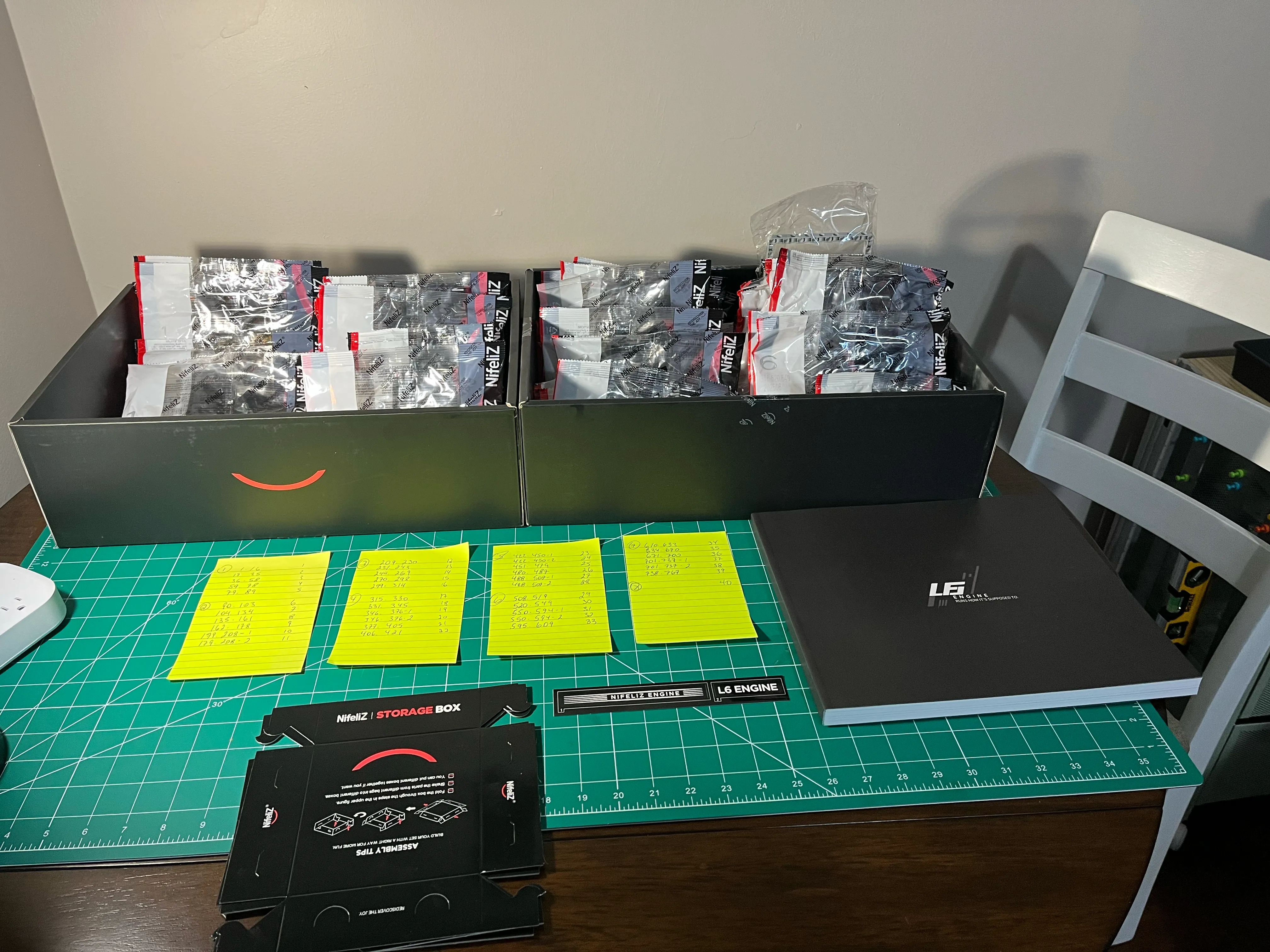
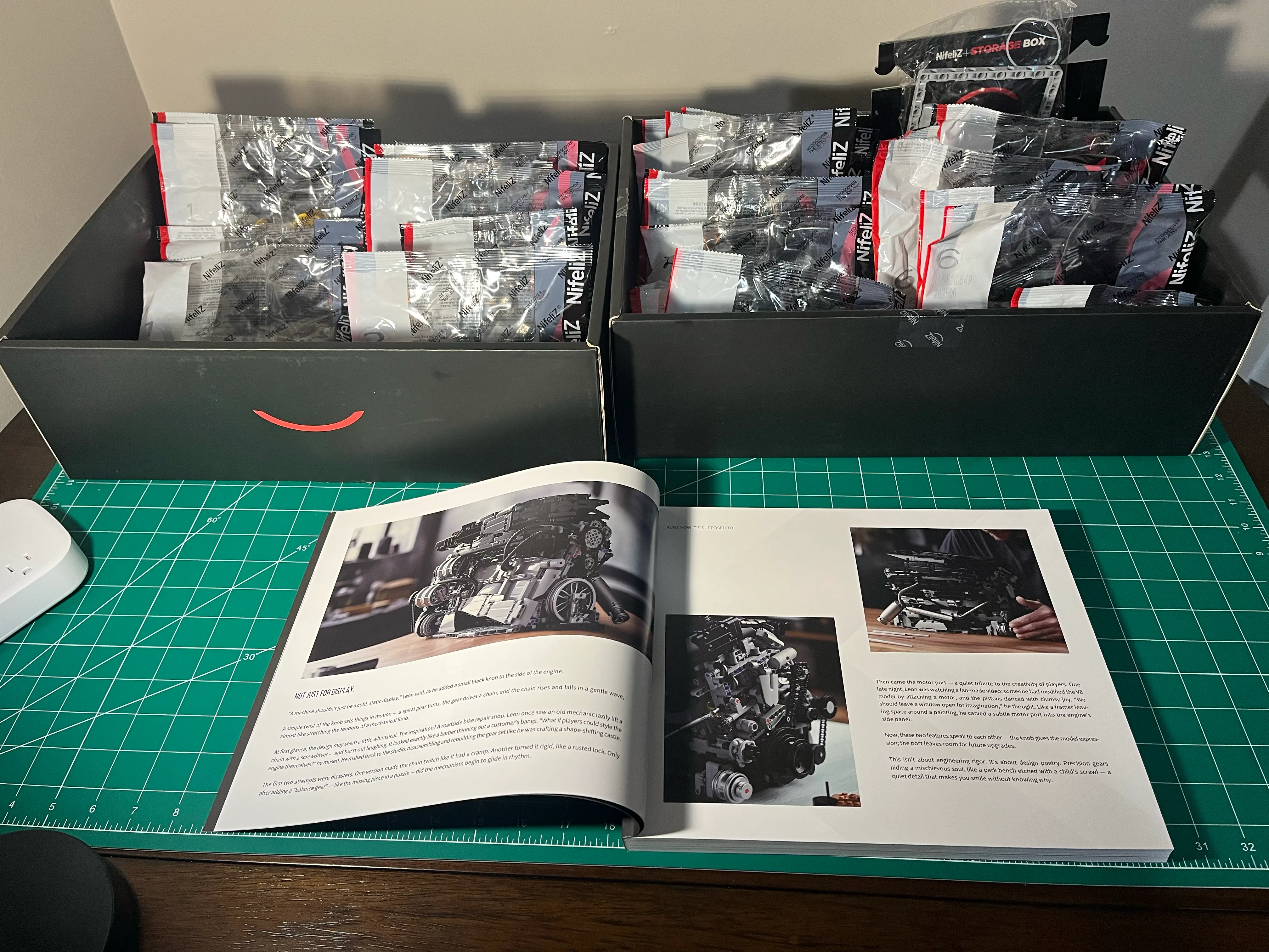
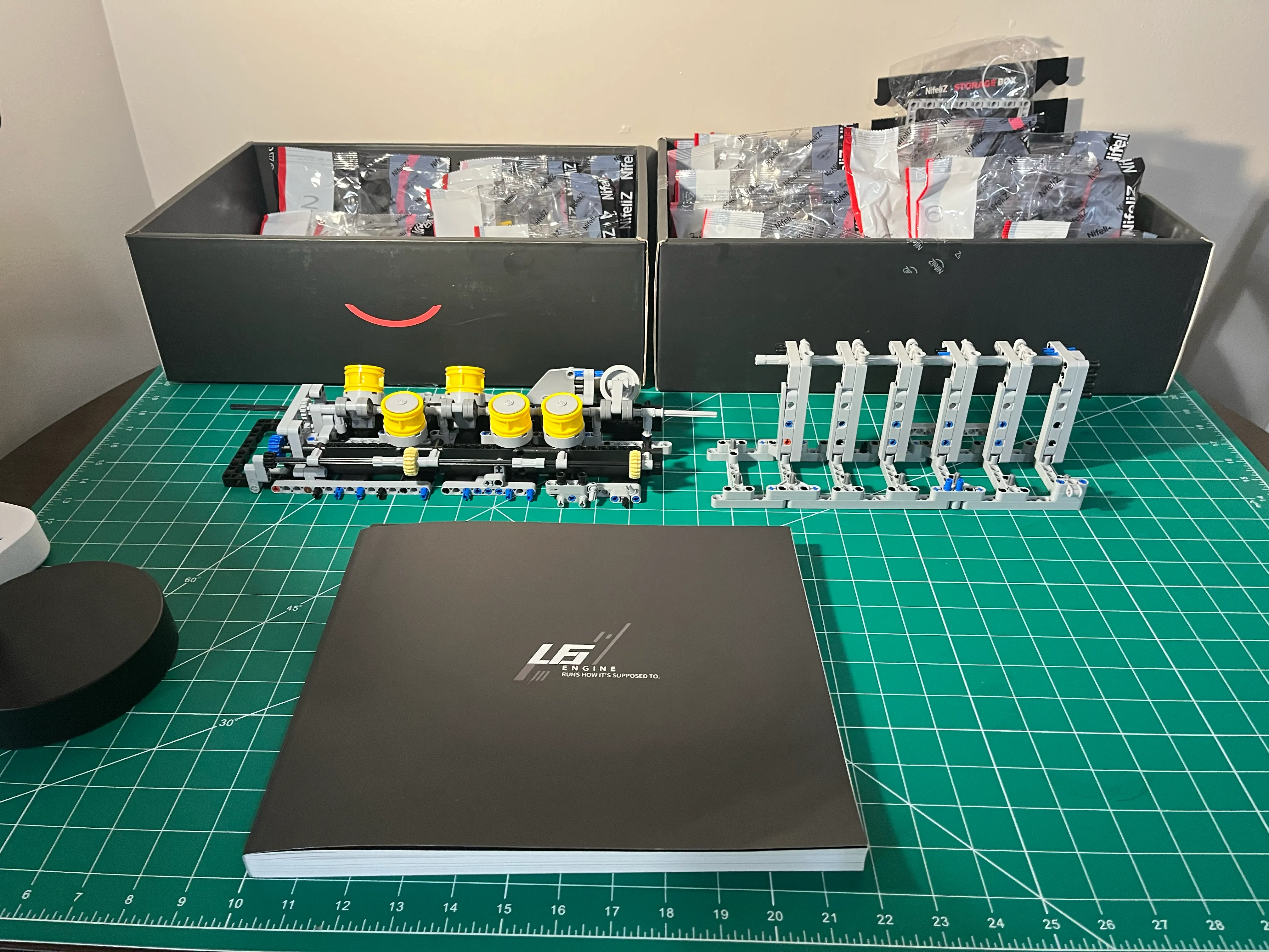
NifeilZ L6 Model Engine
2026-04-06
Assembling the NifeilZ L6: A hands-on dive into mechanical systems and engine architecture.
Overview
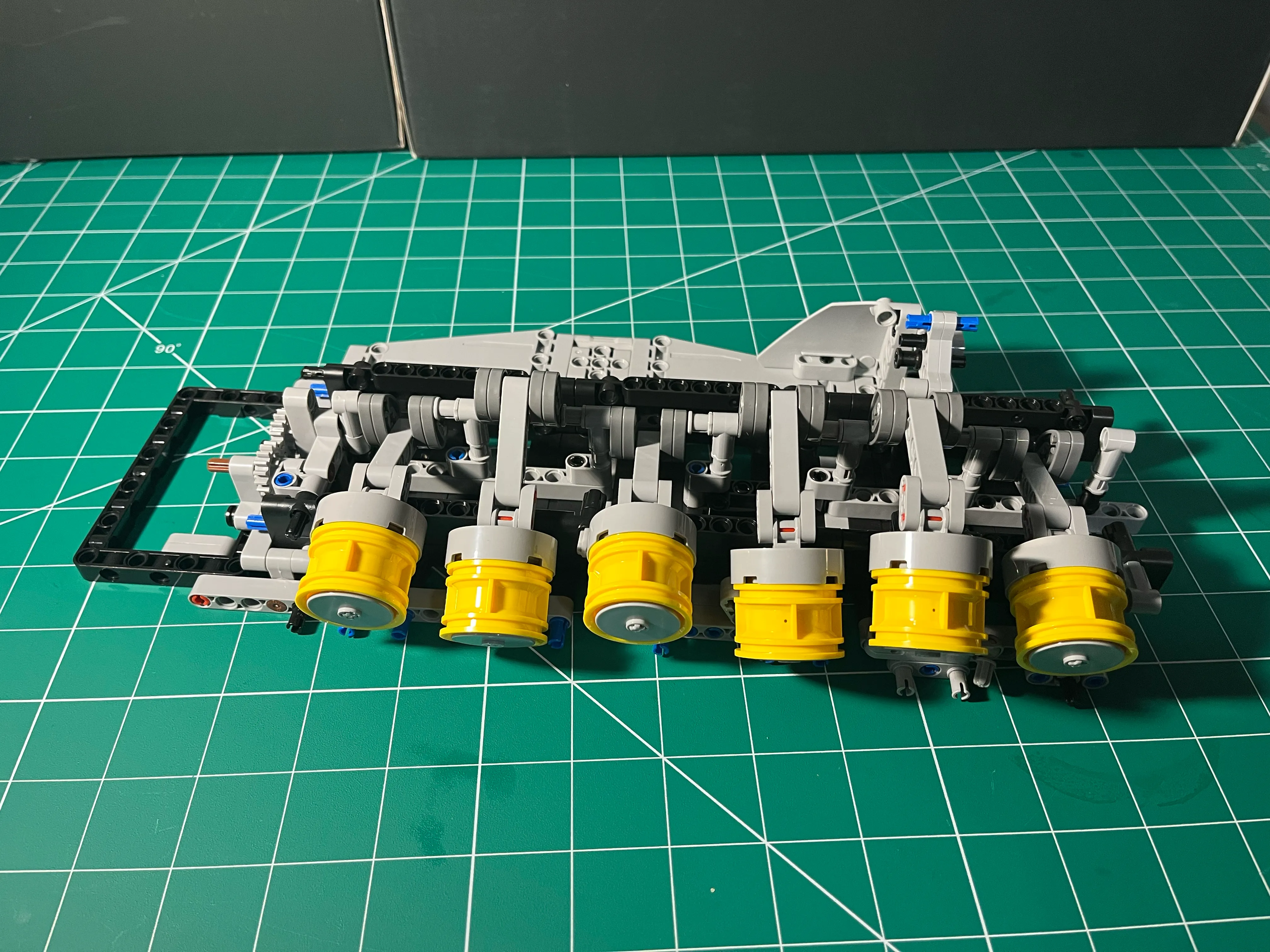
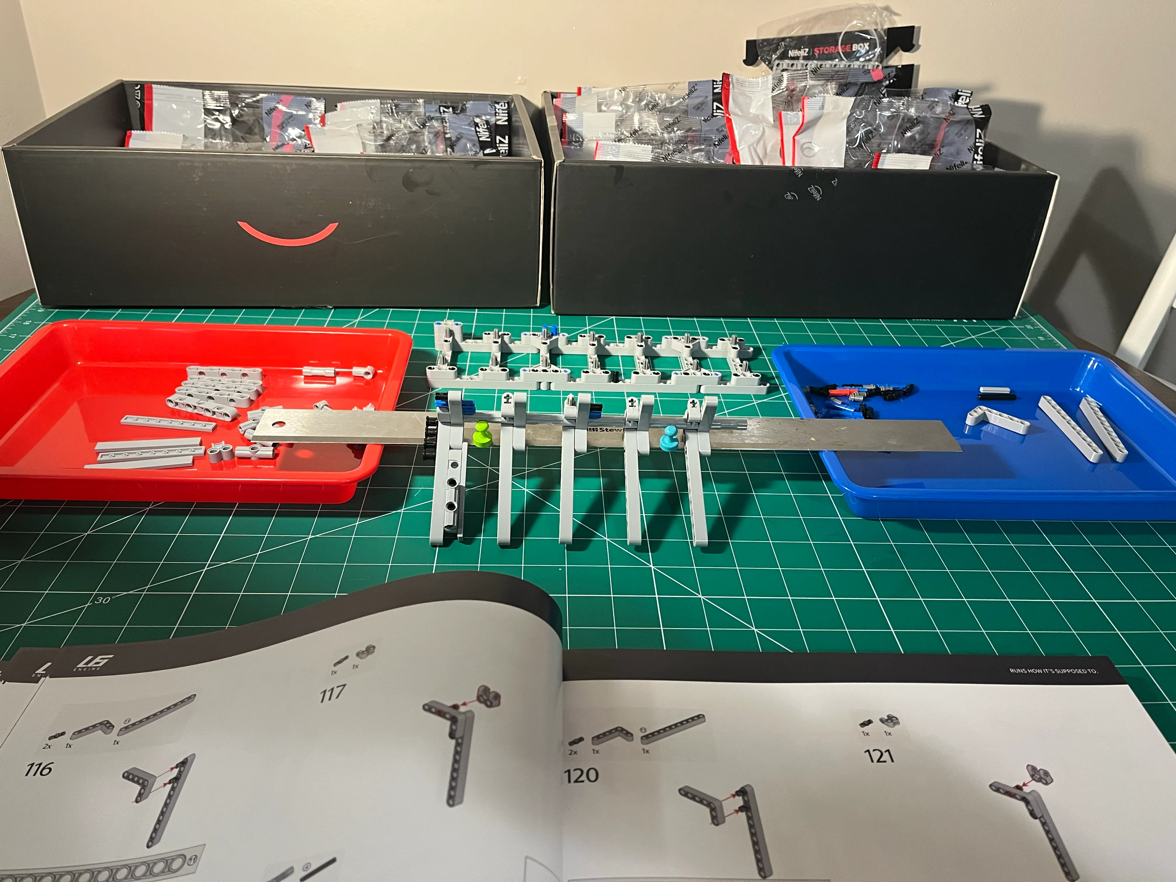
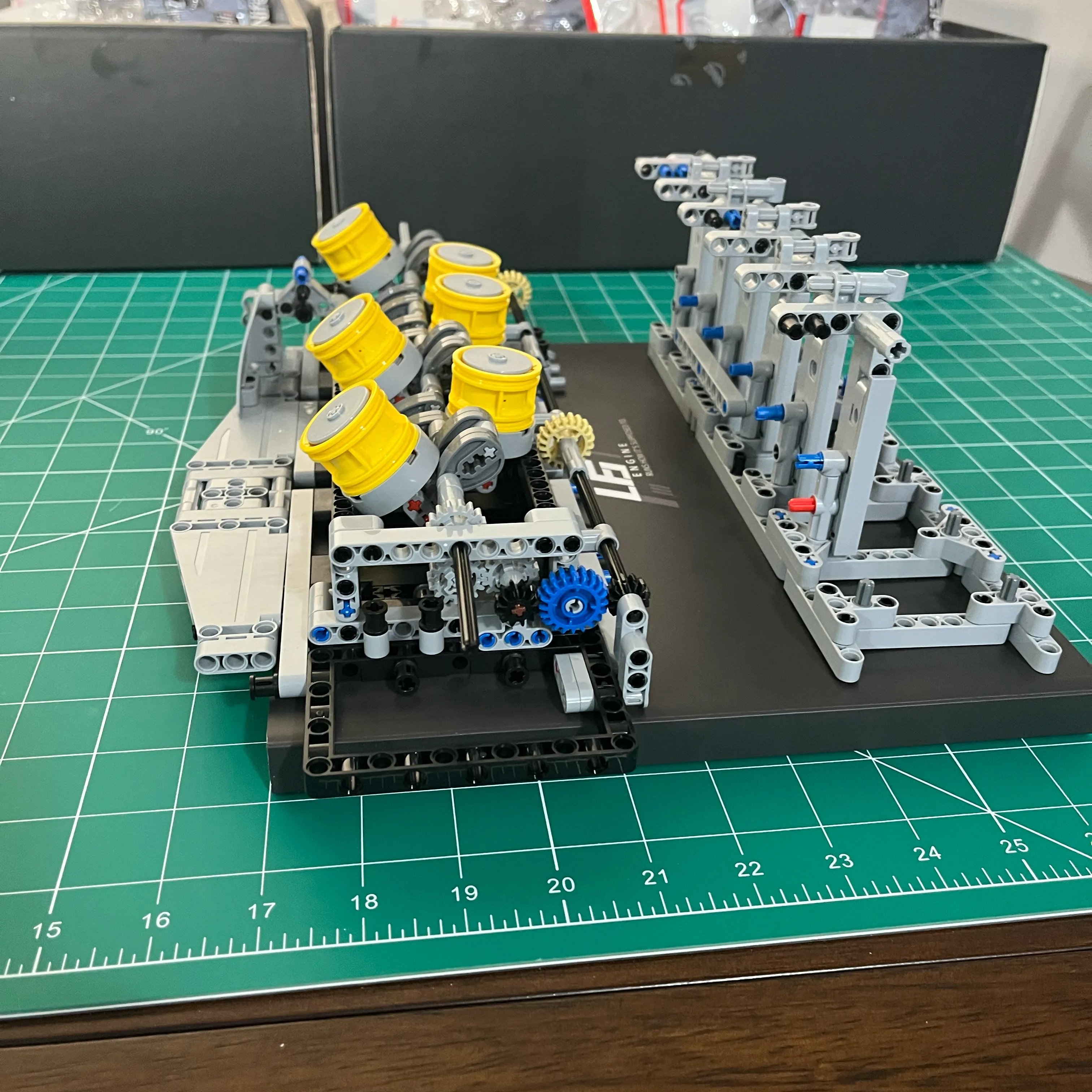
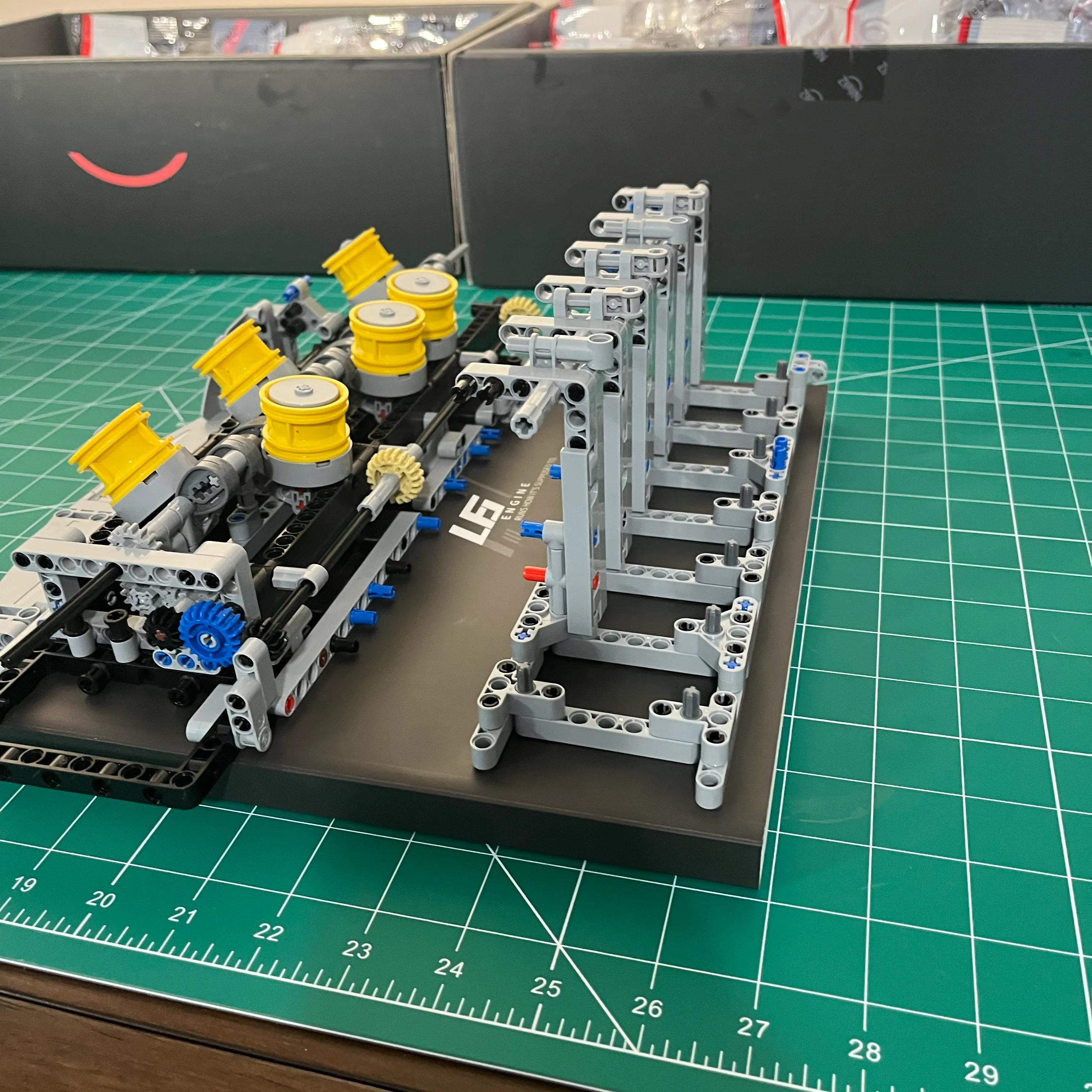
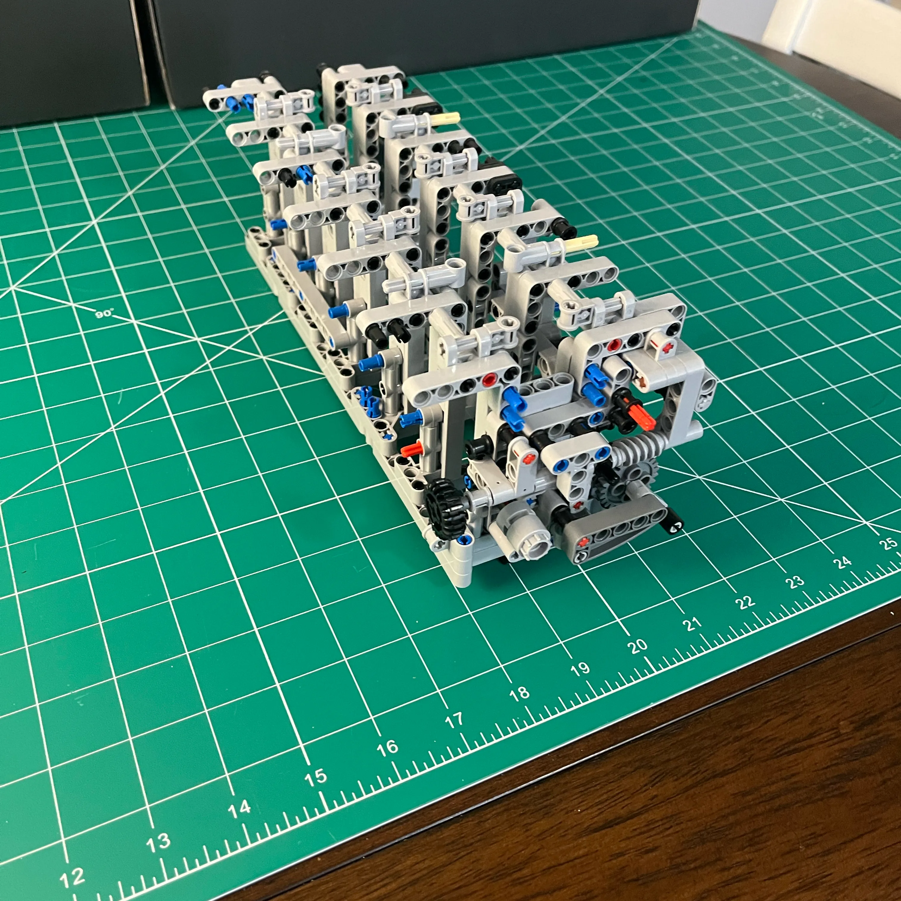
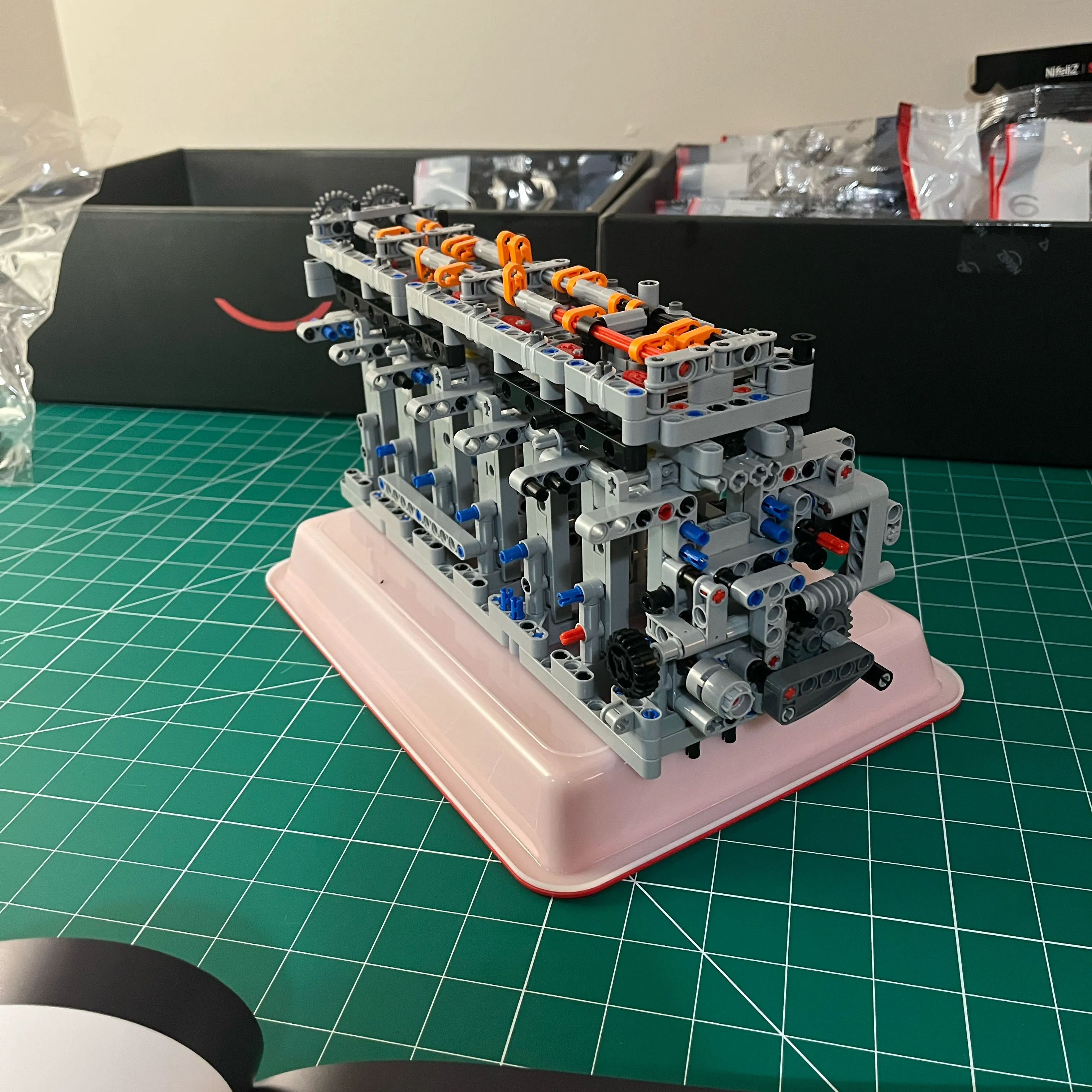
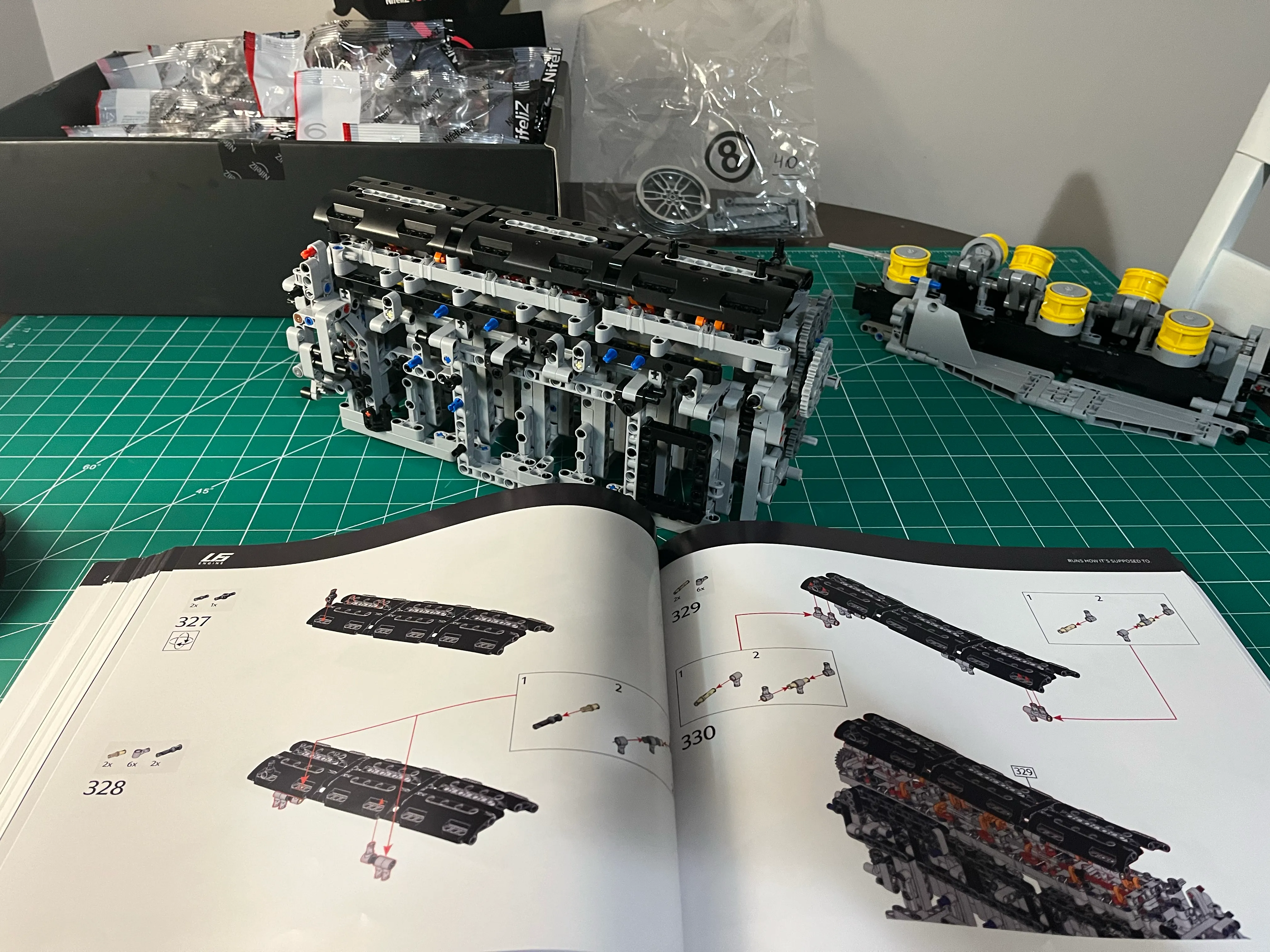
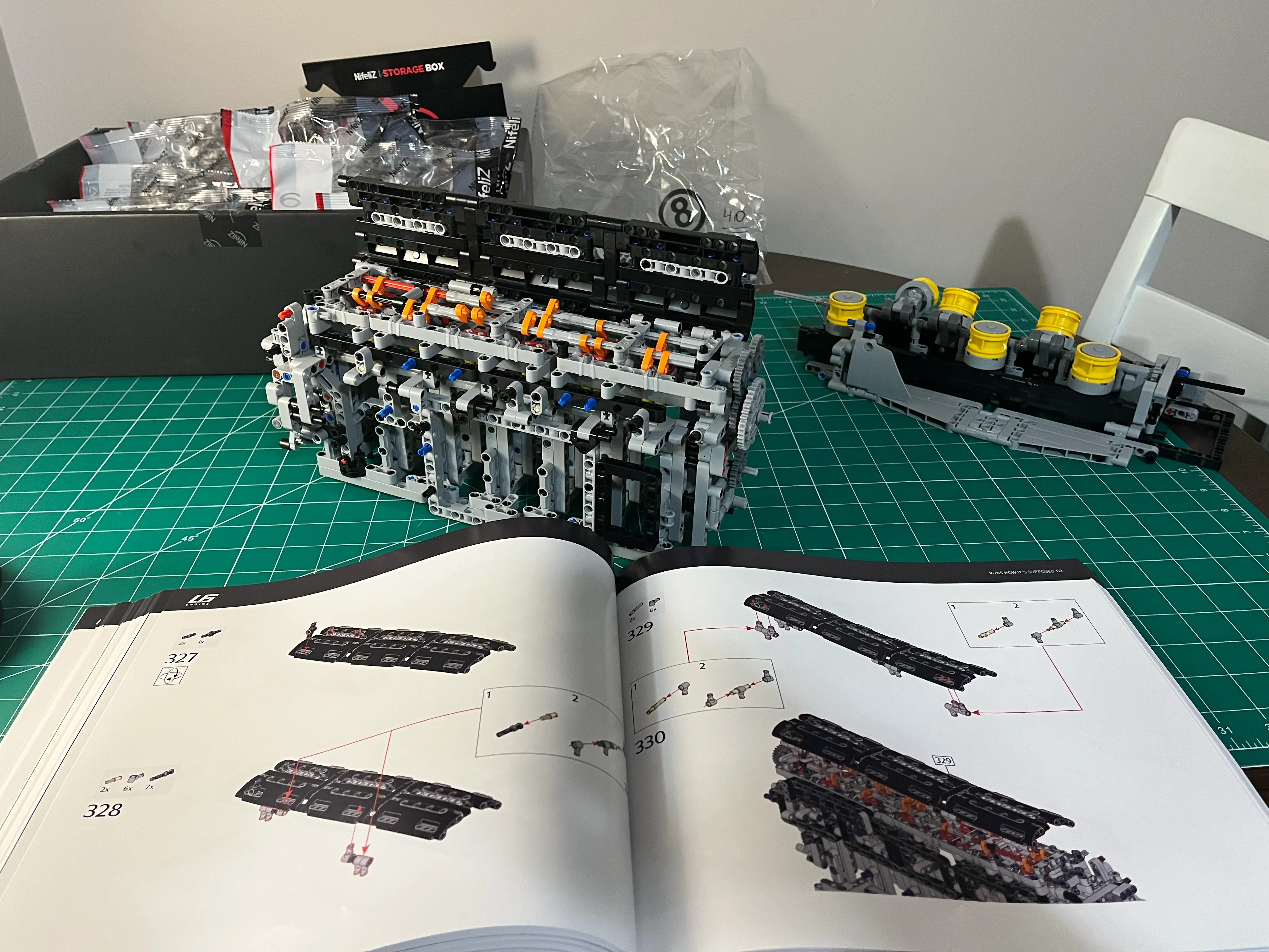
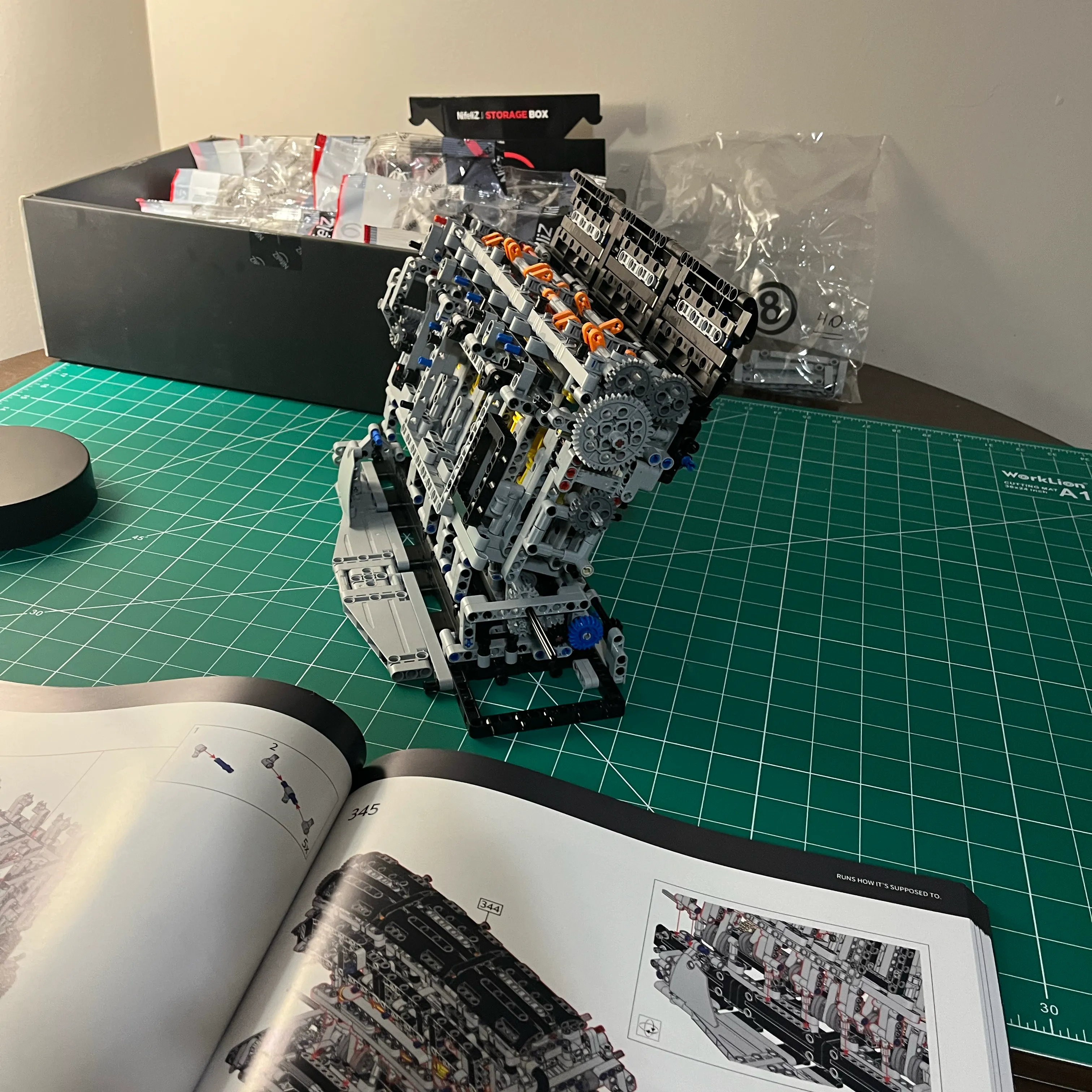
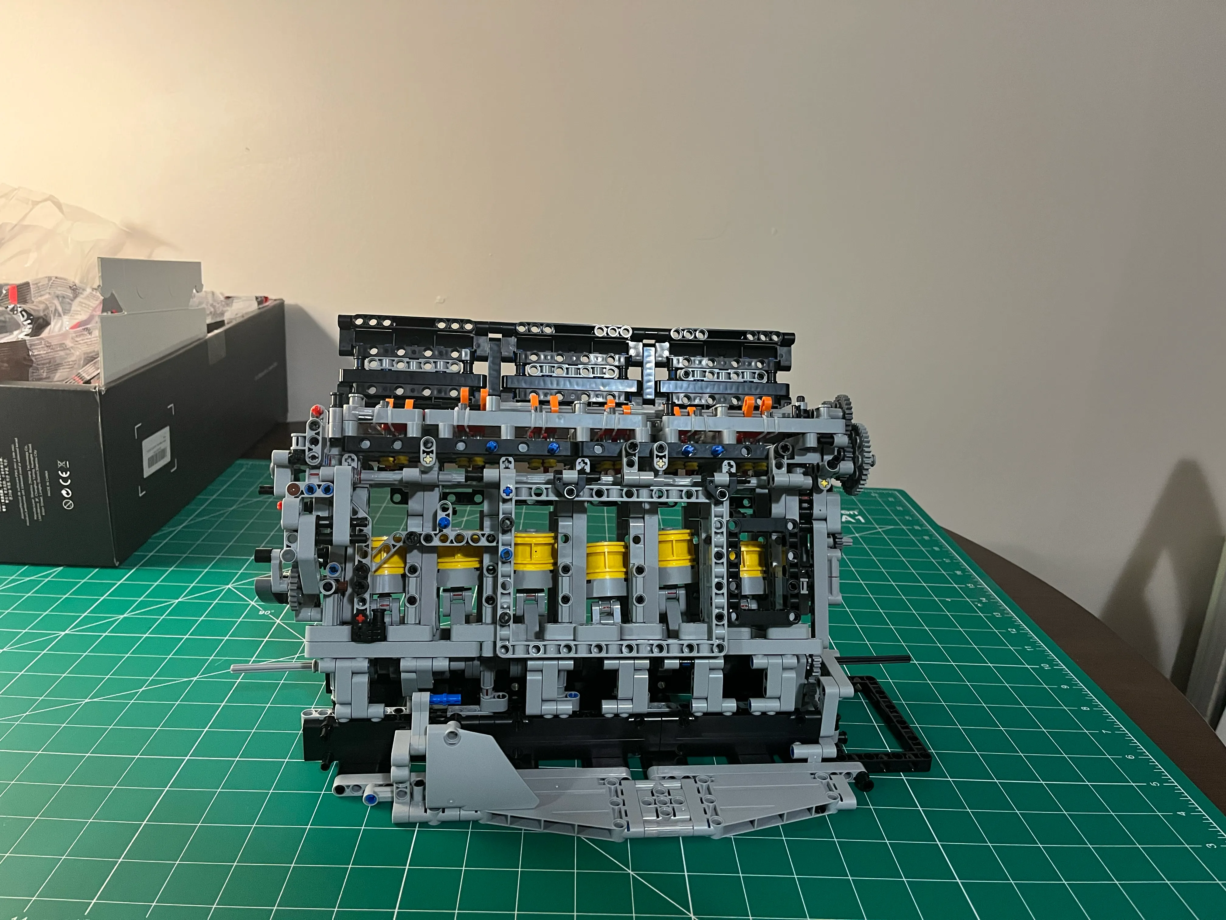
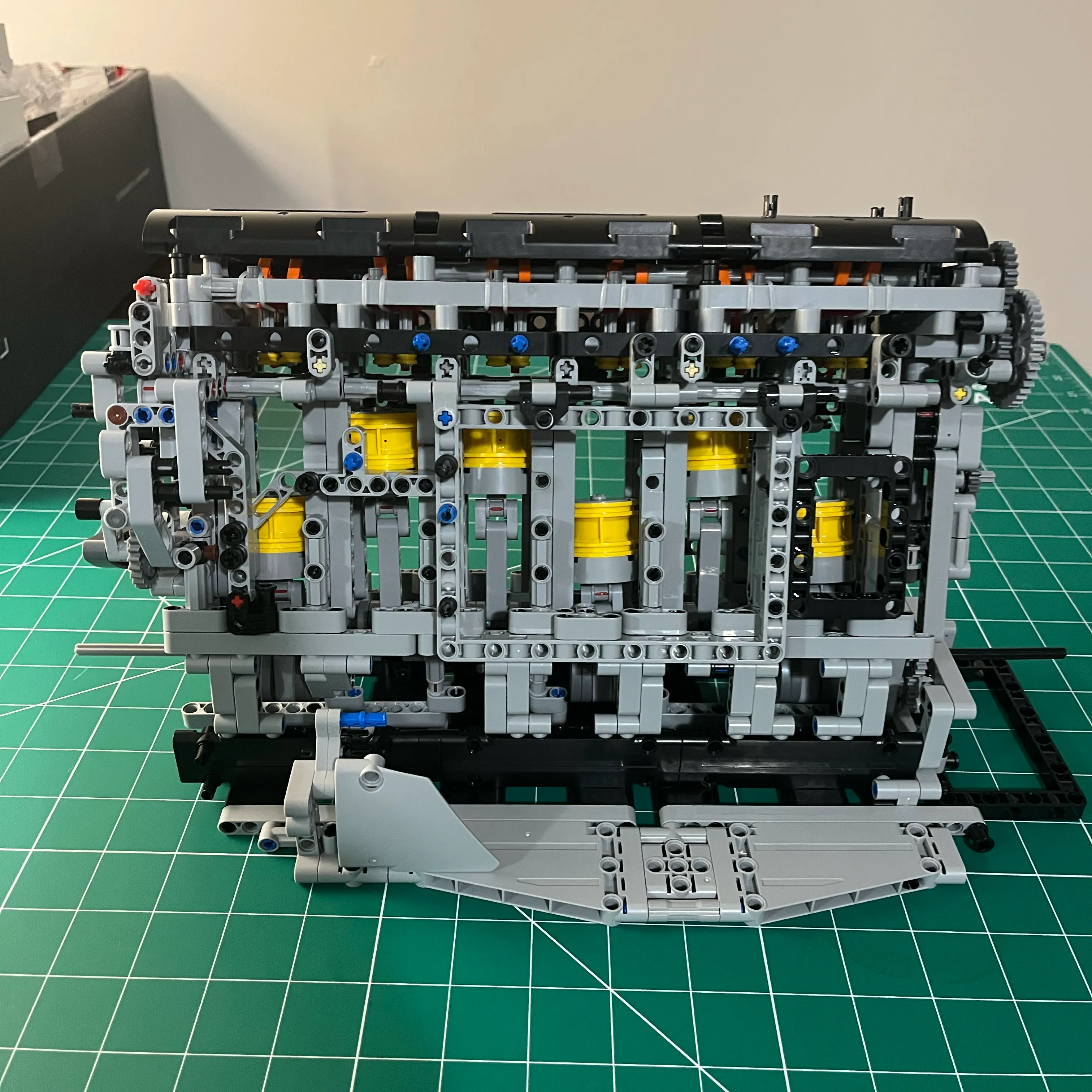
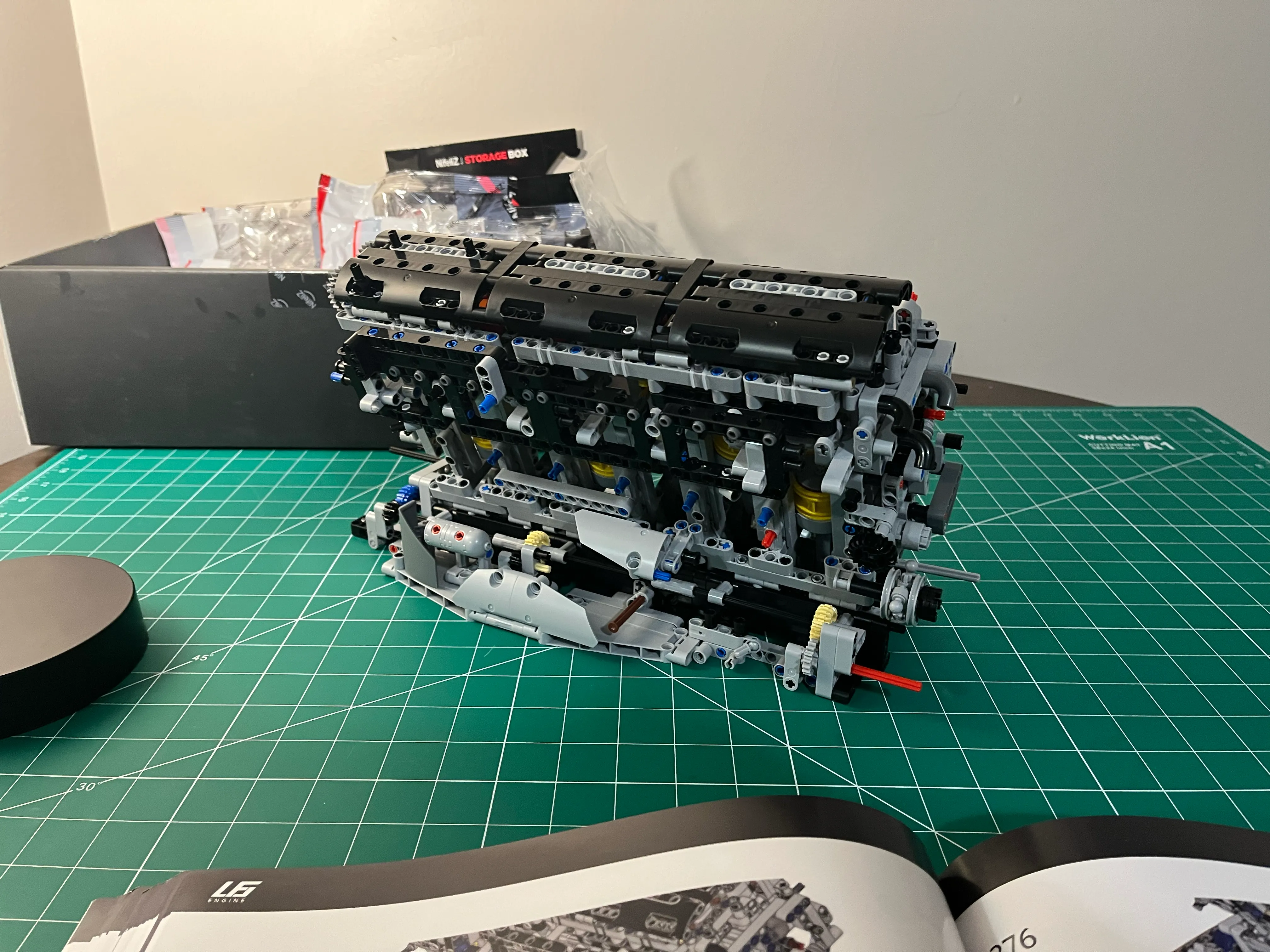
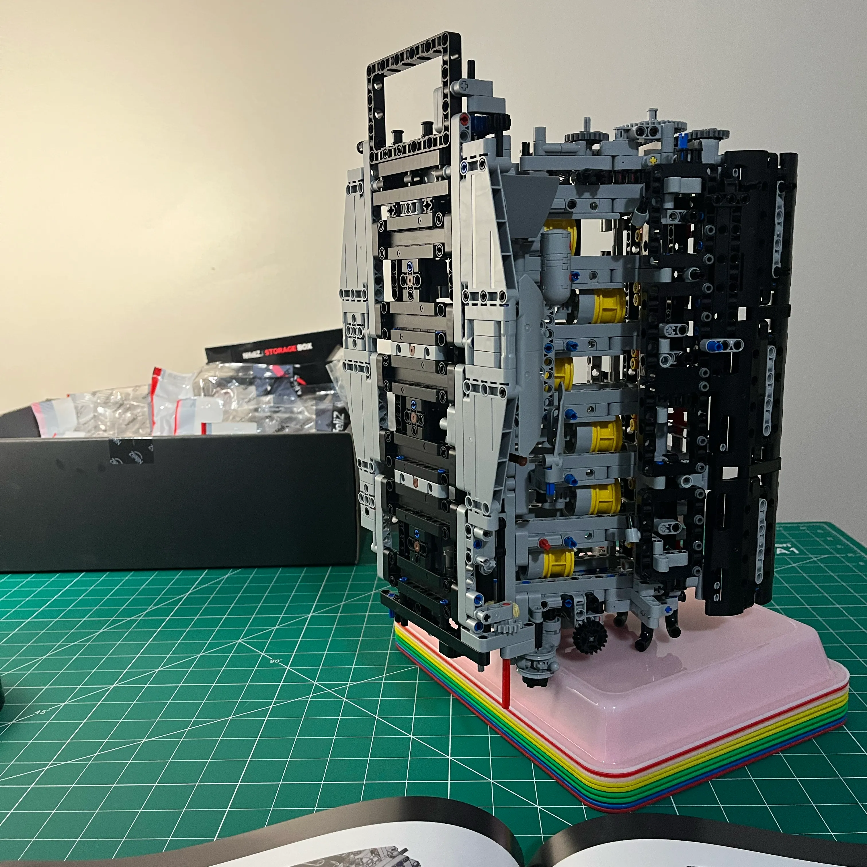
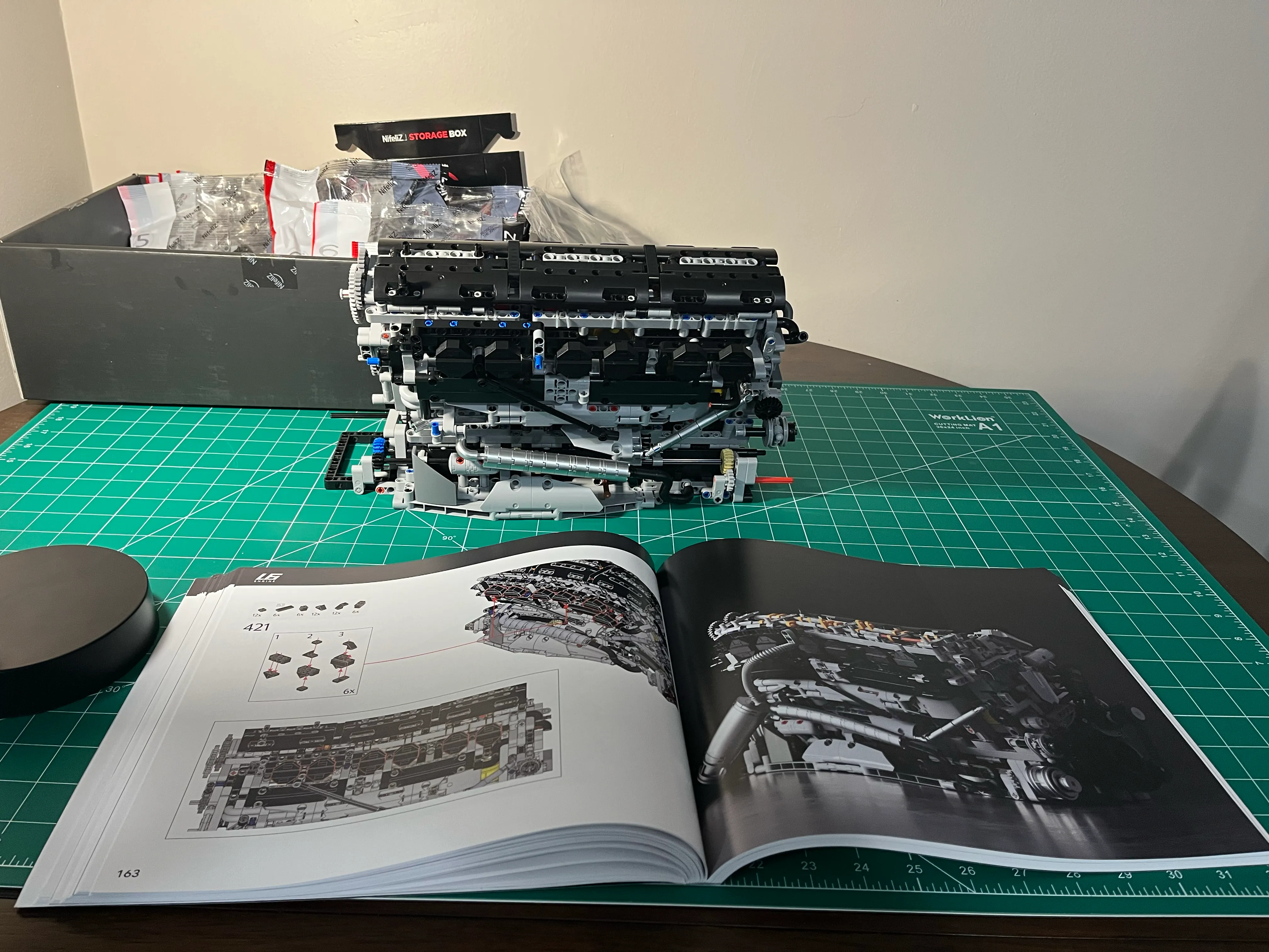
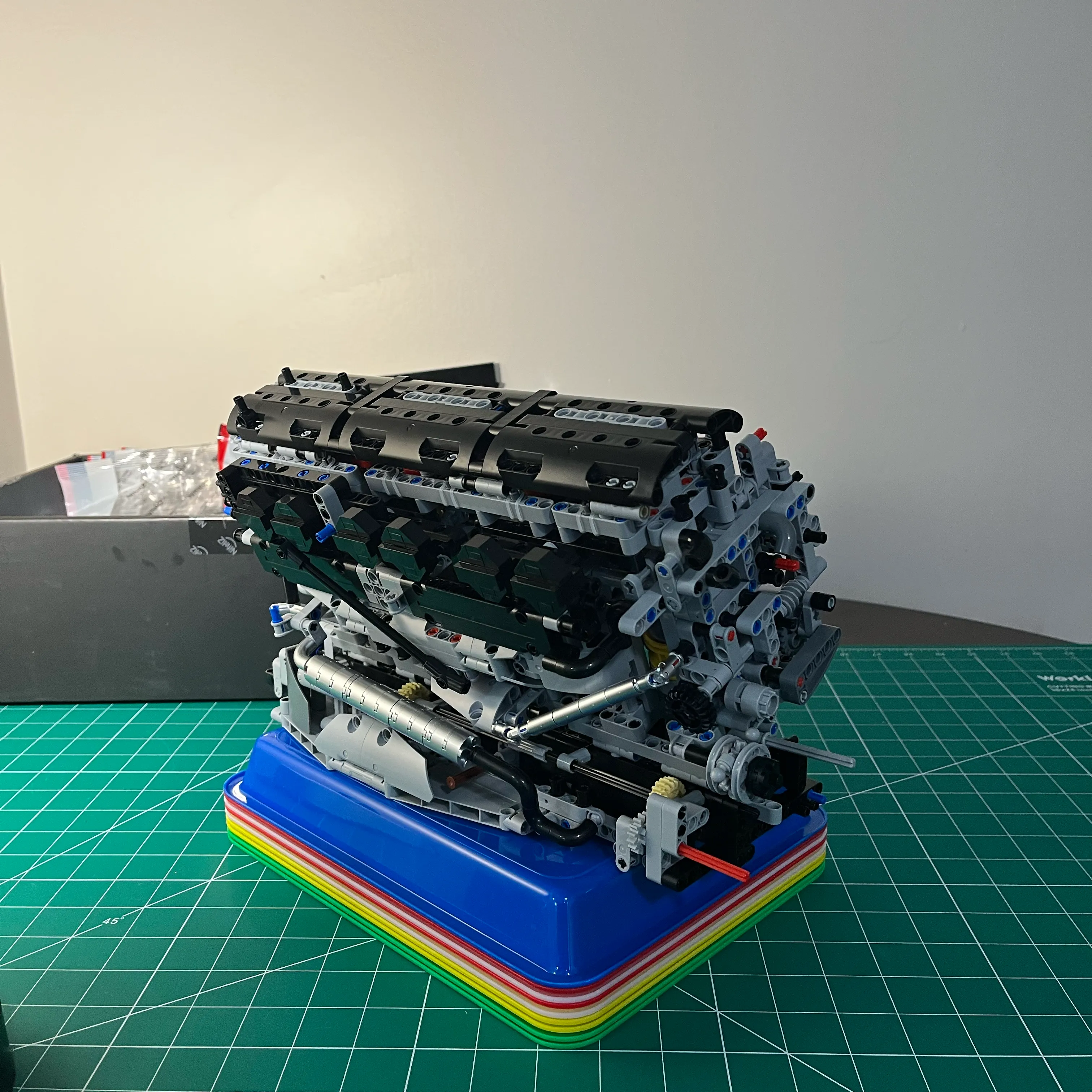
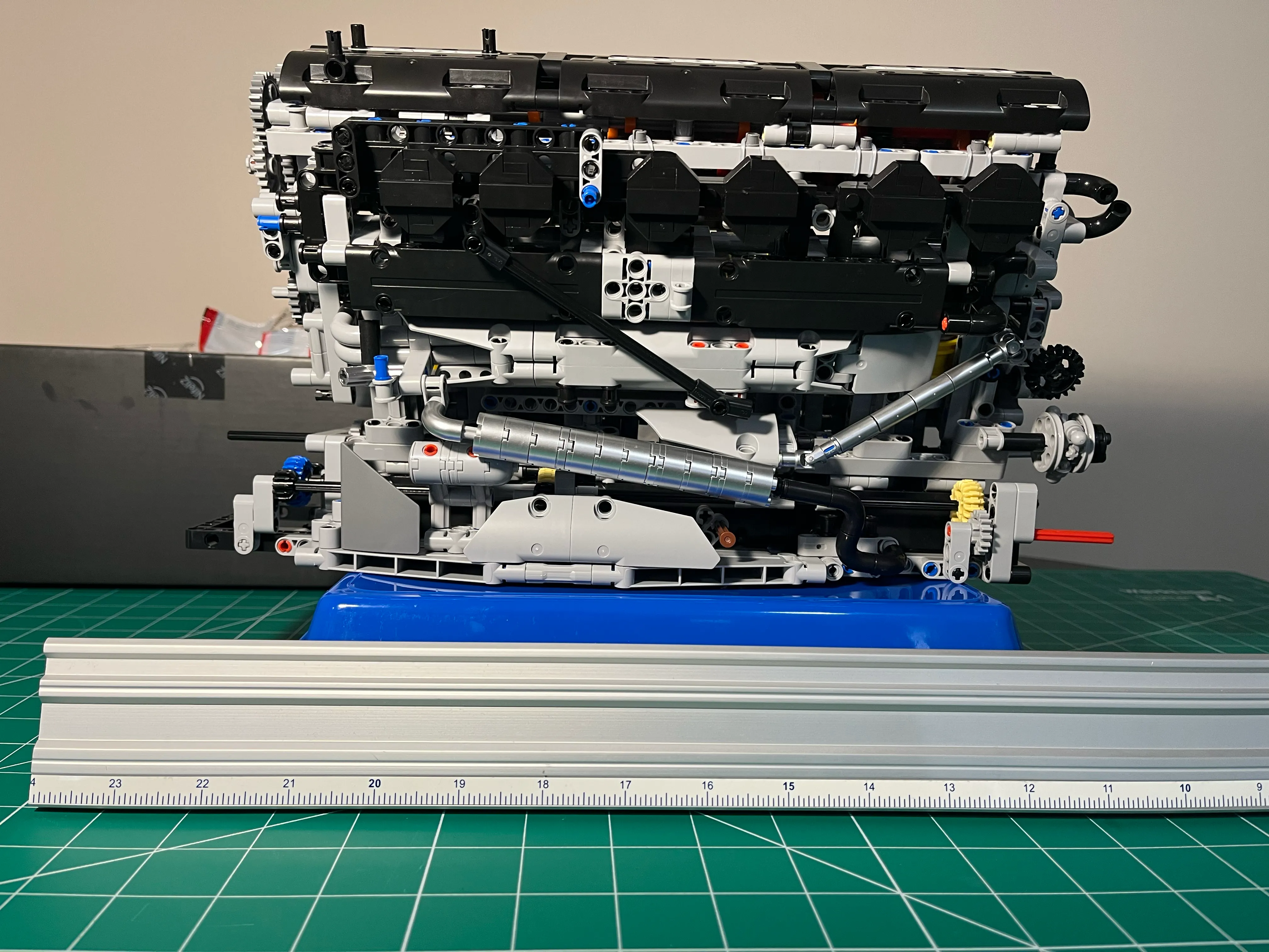
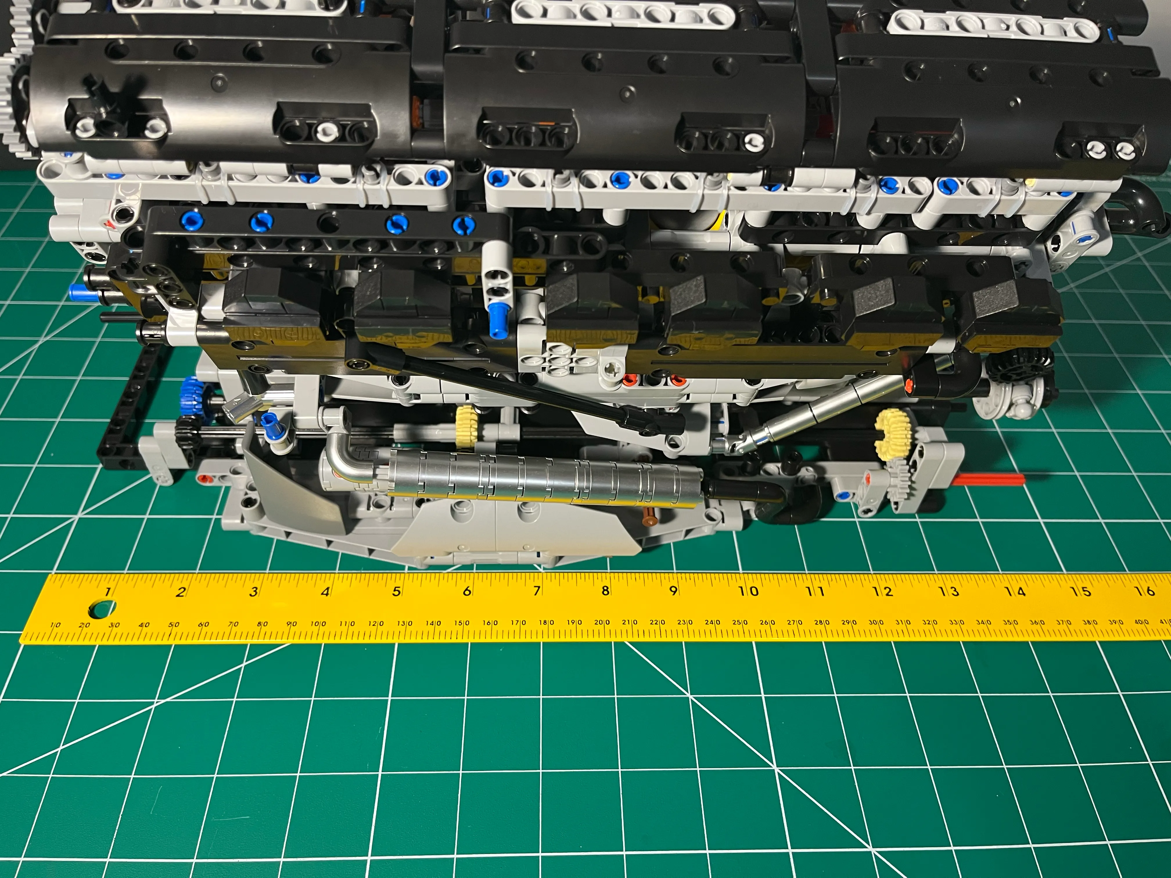
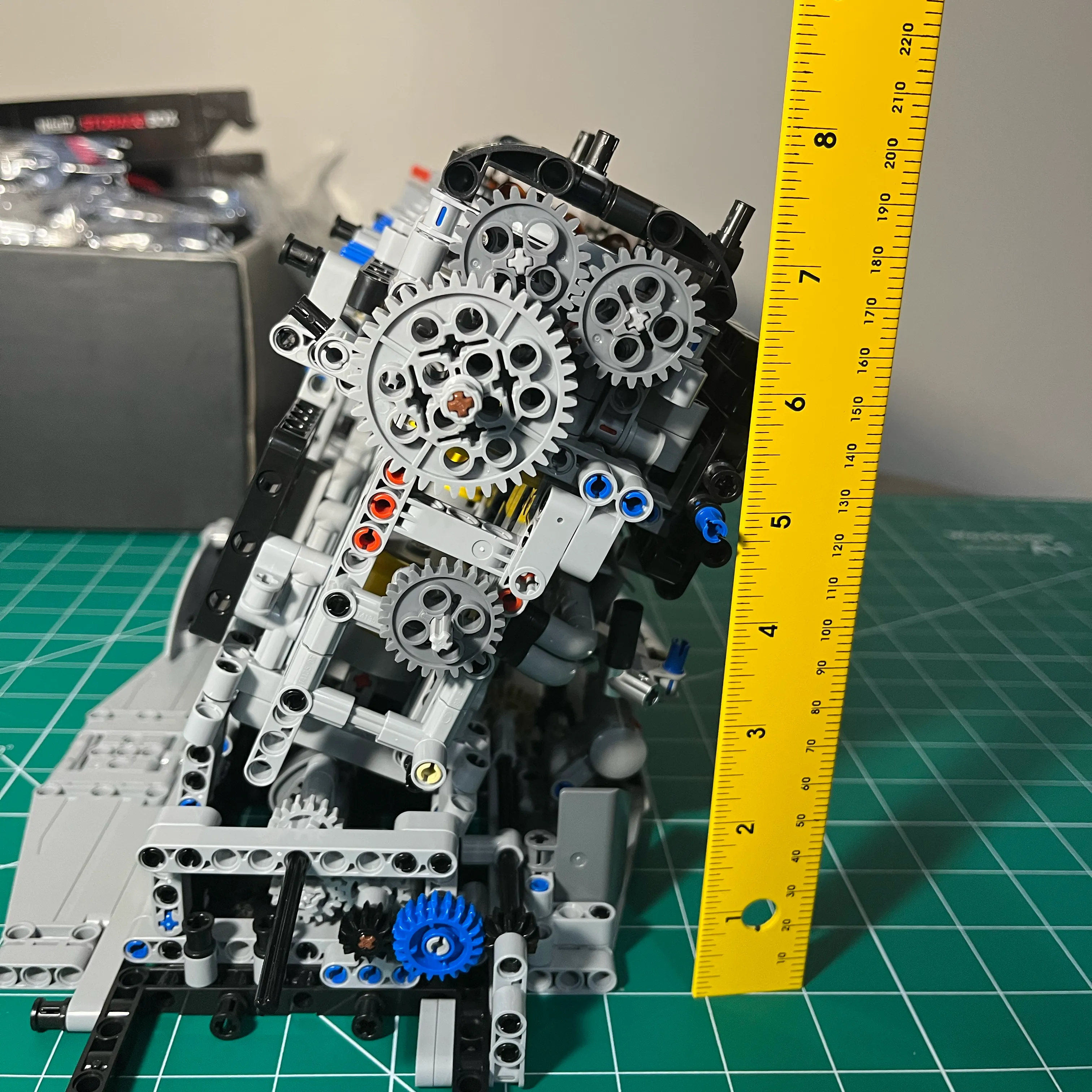
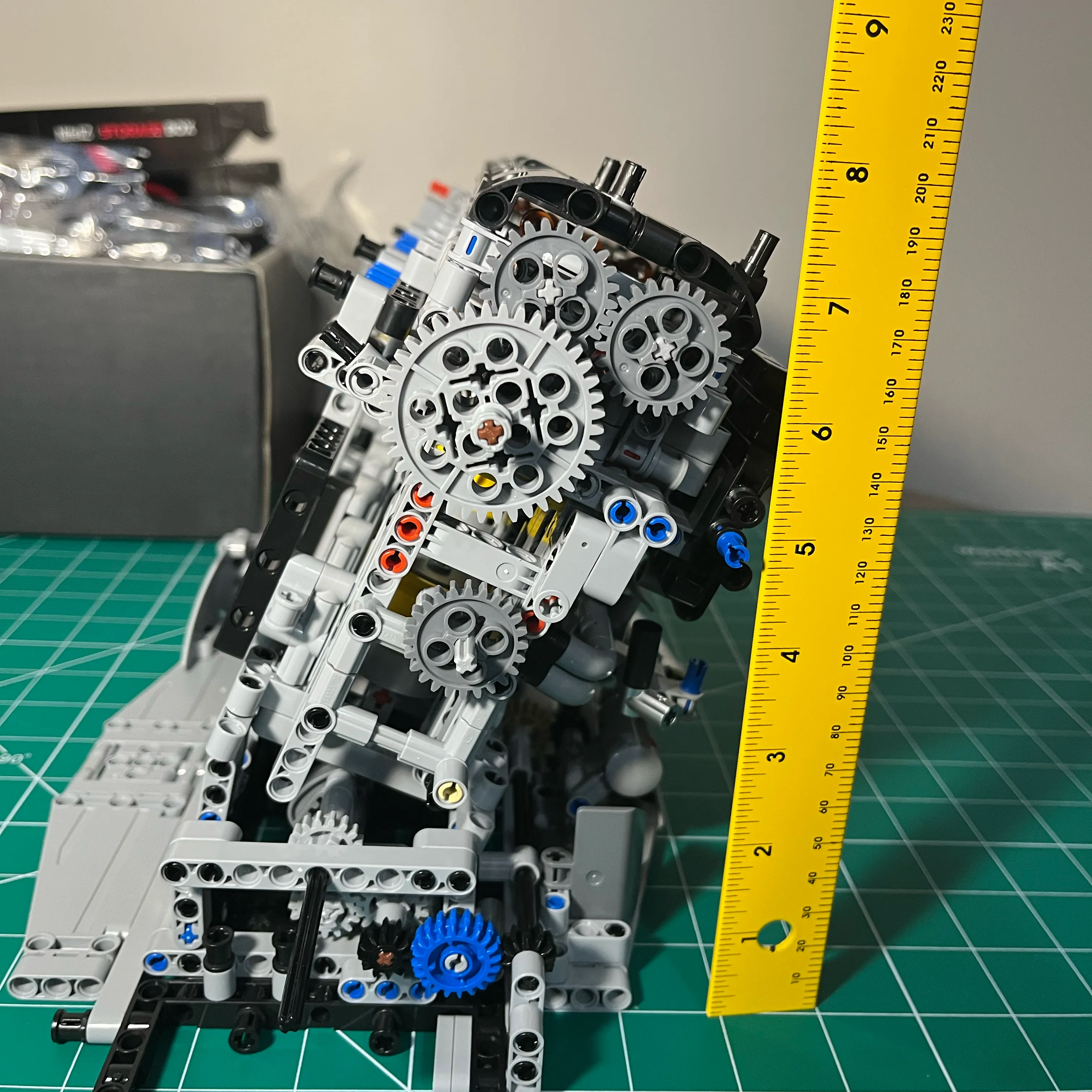
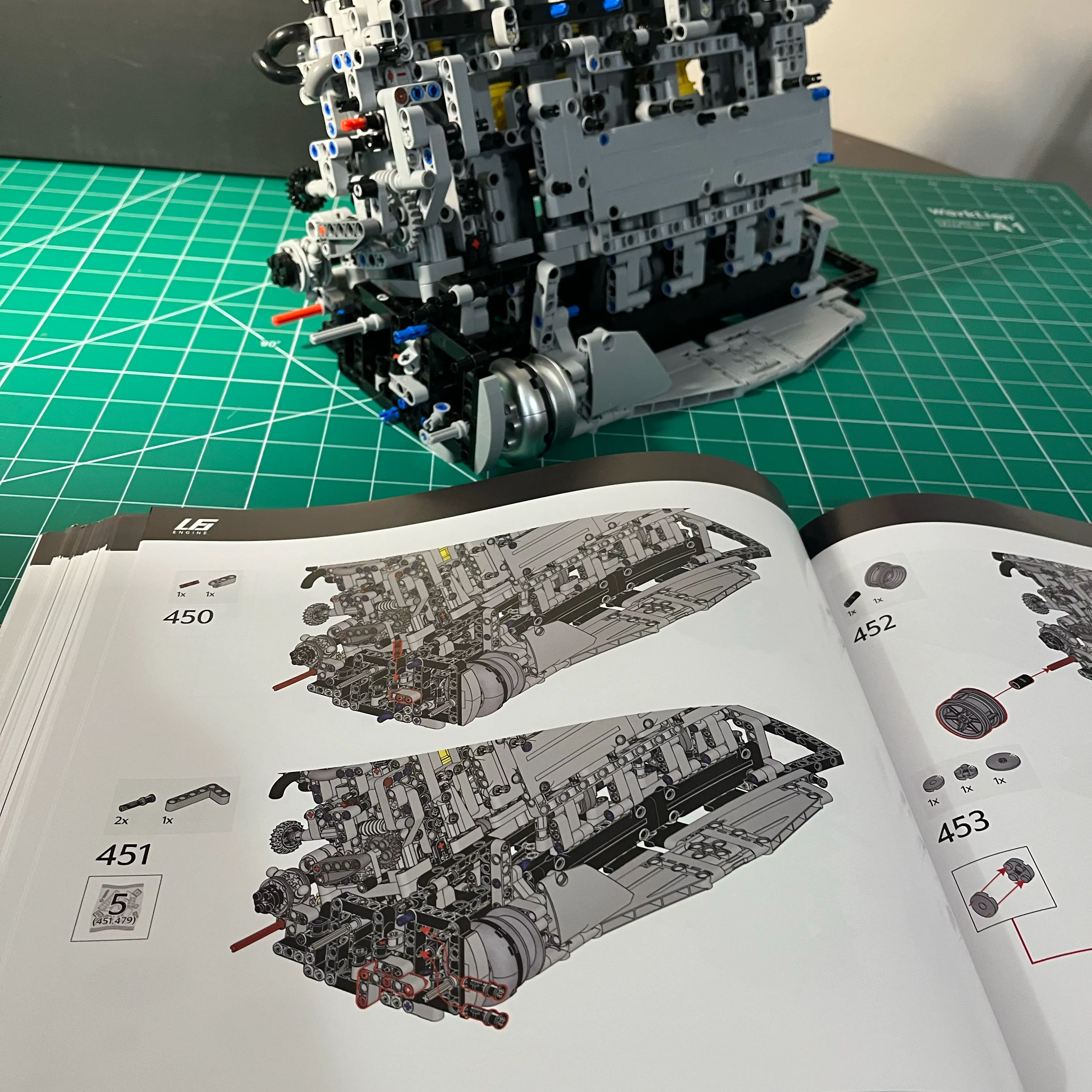
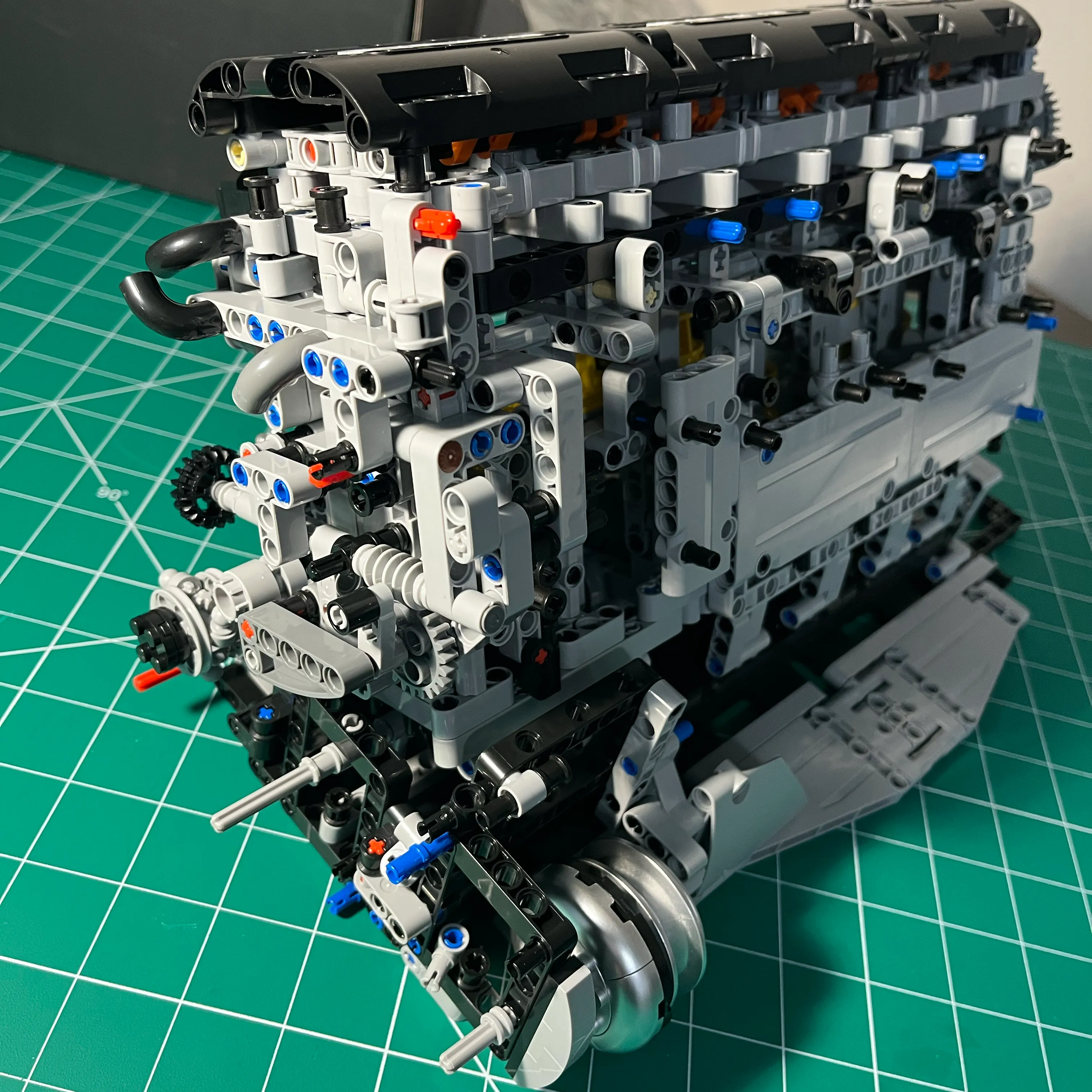
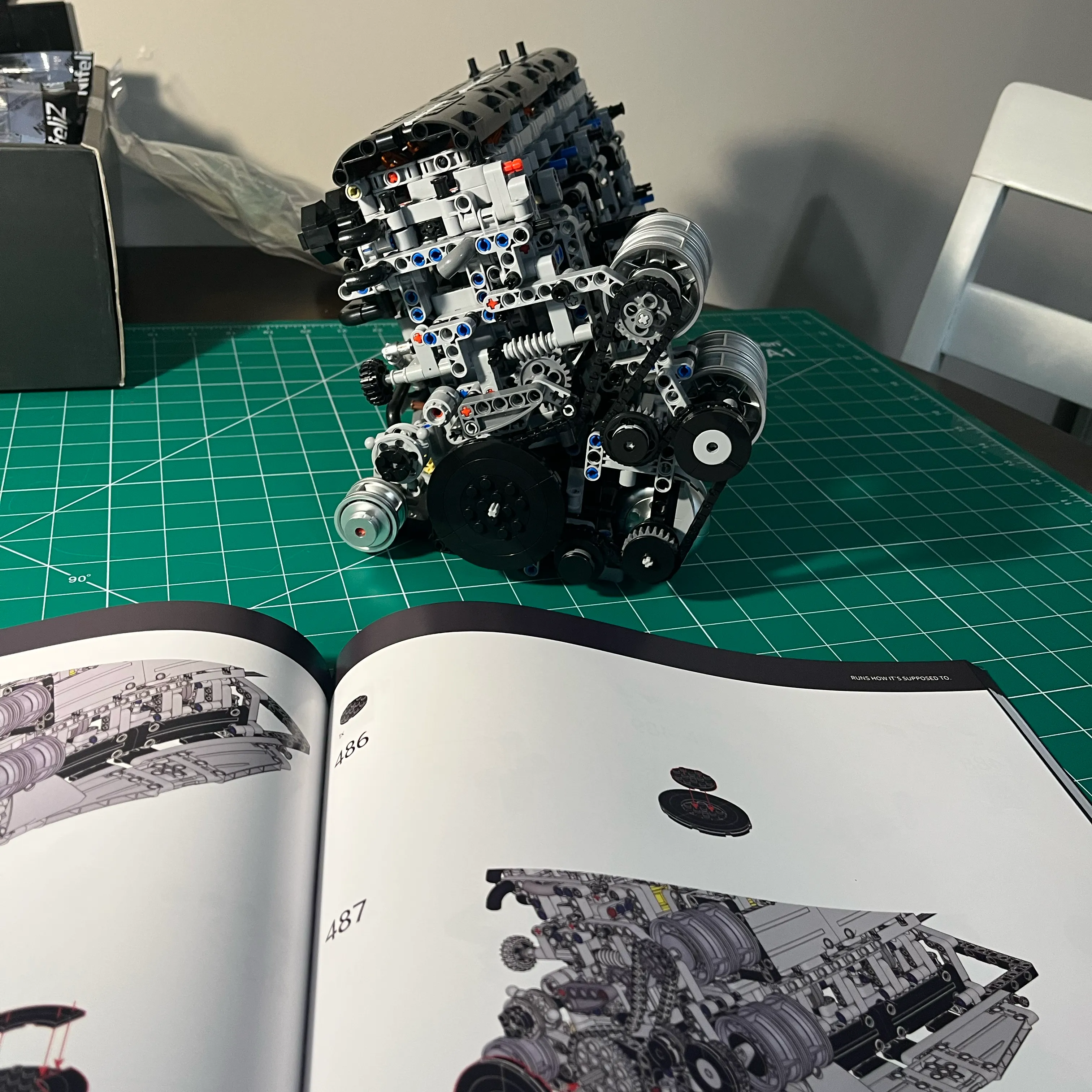
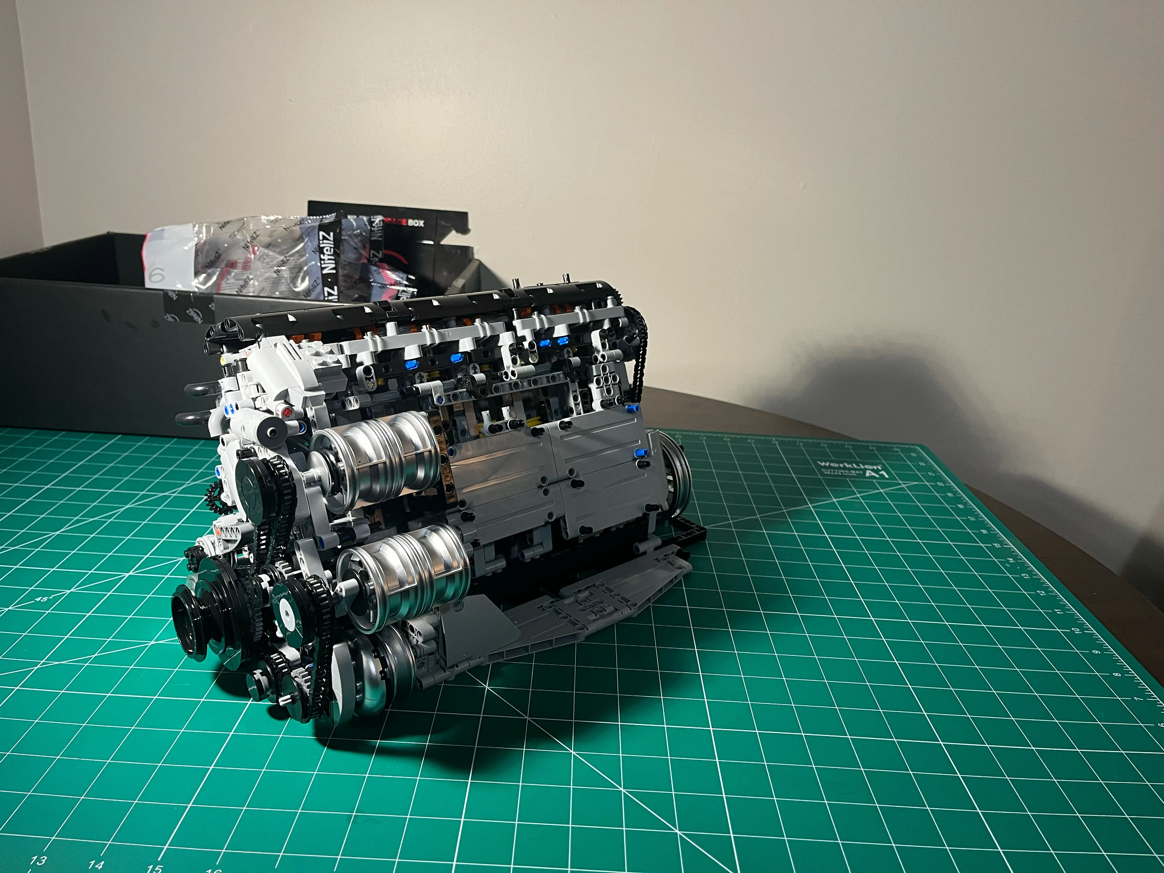
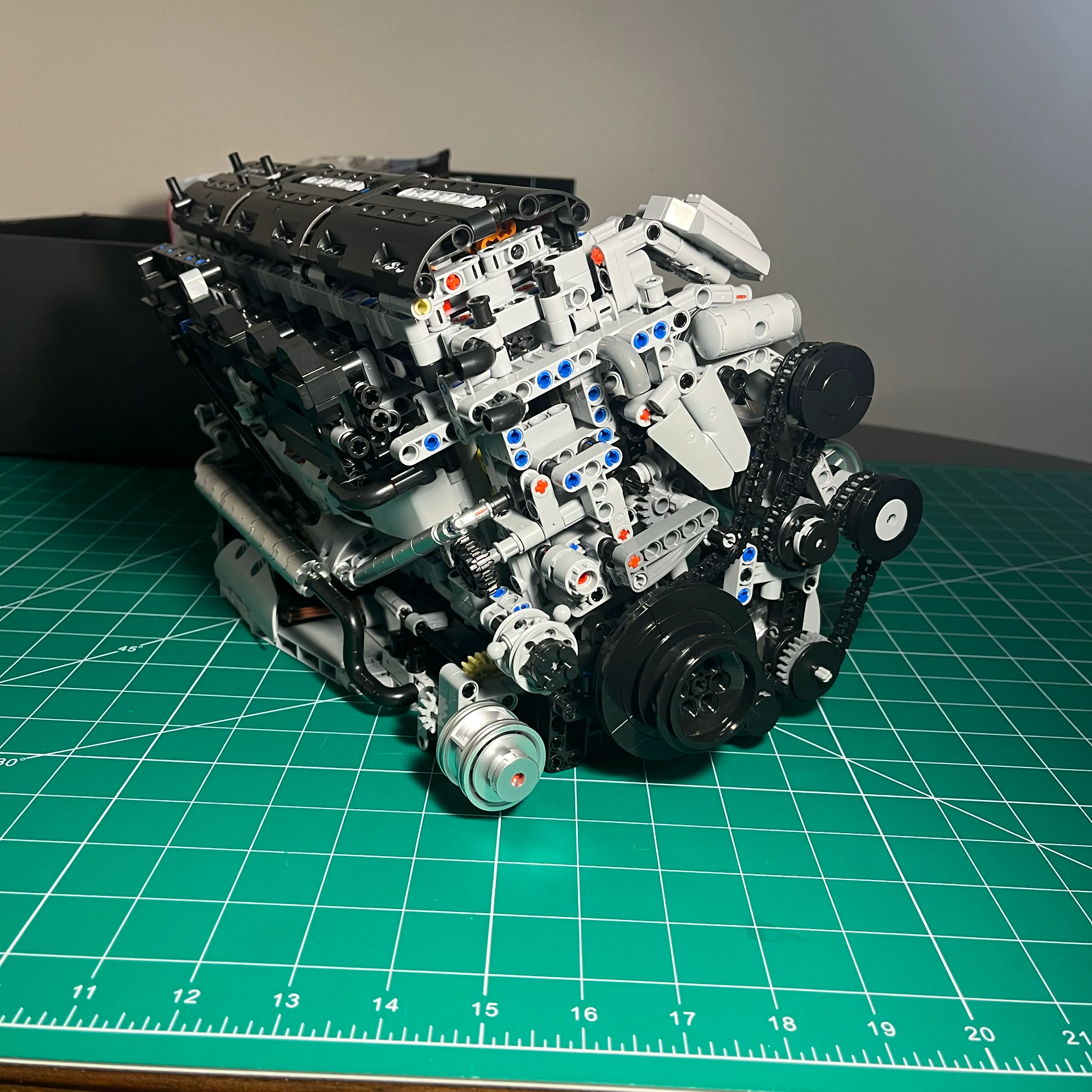
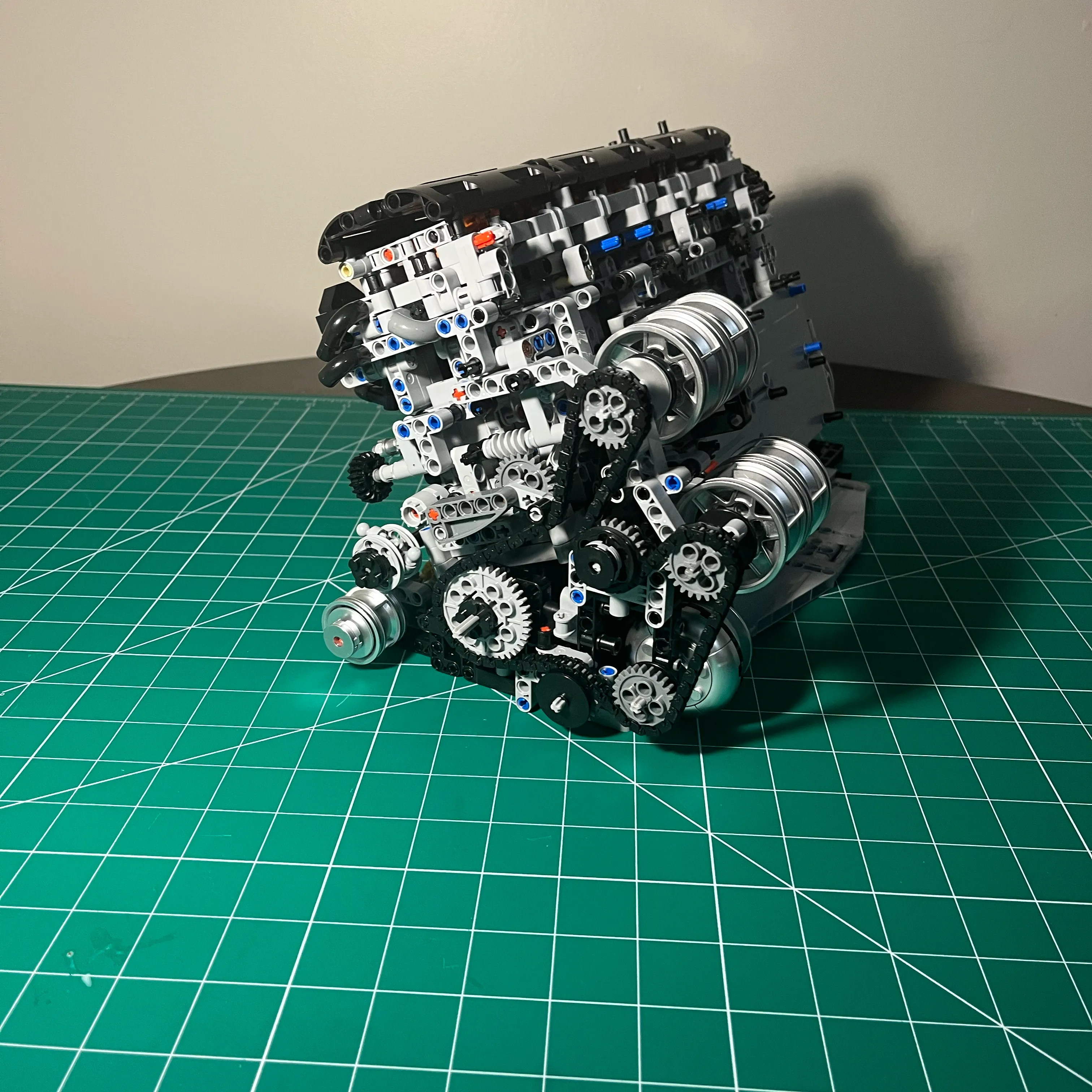
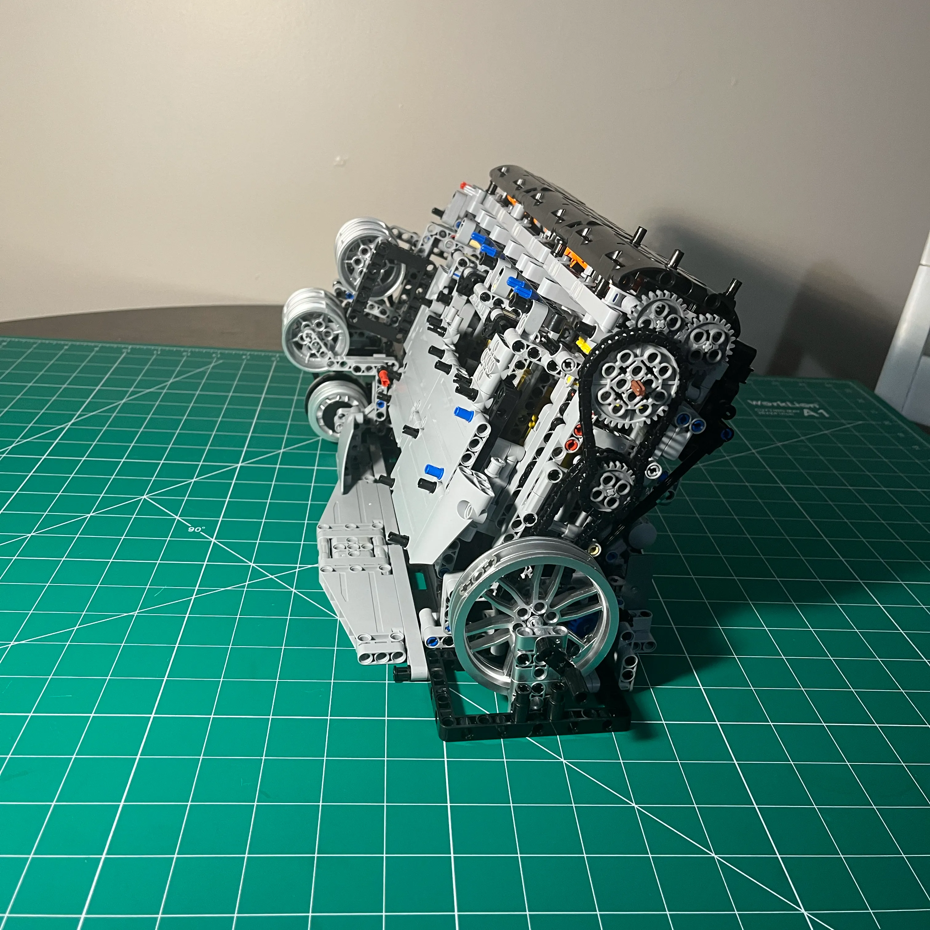
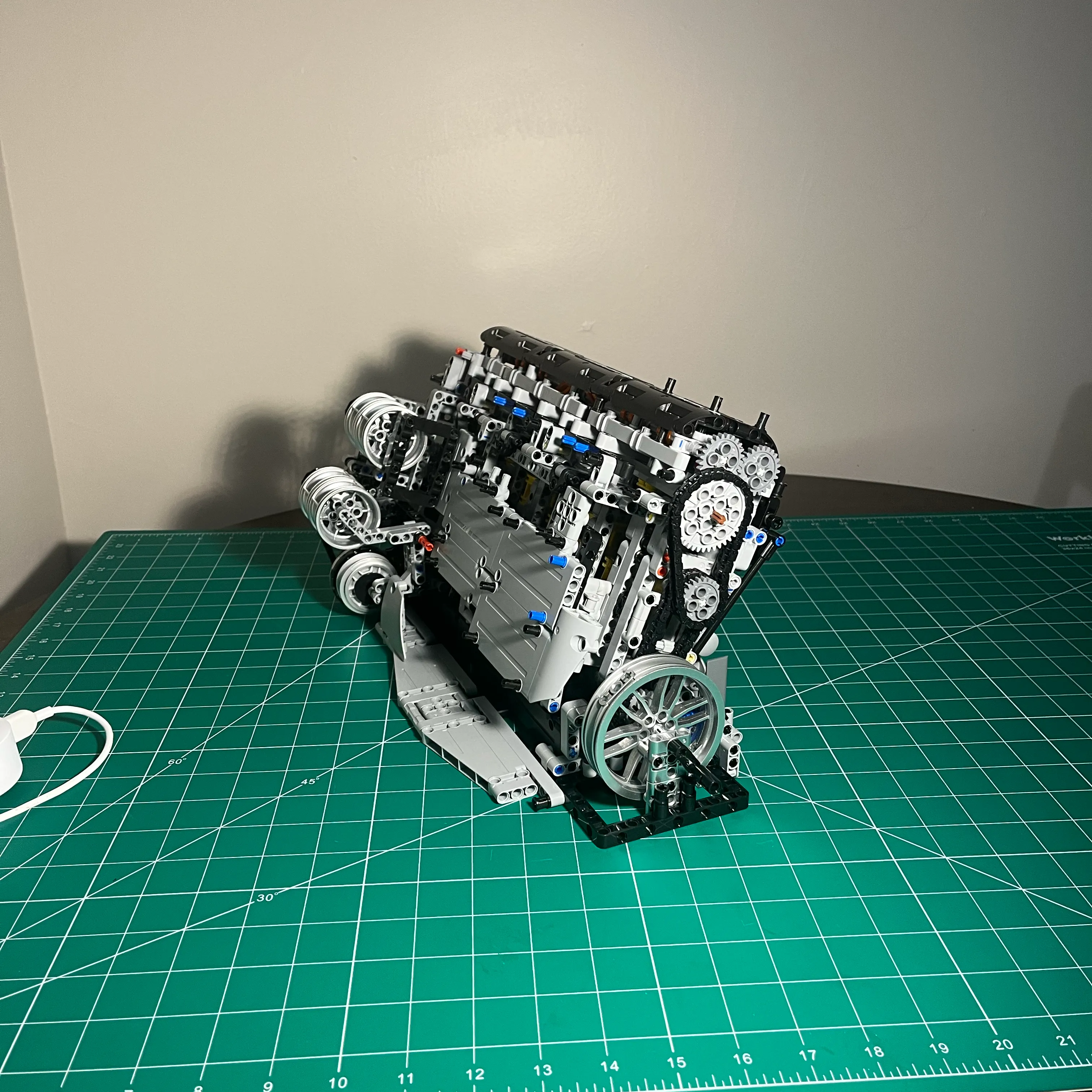
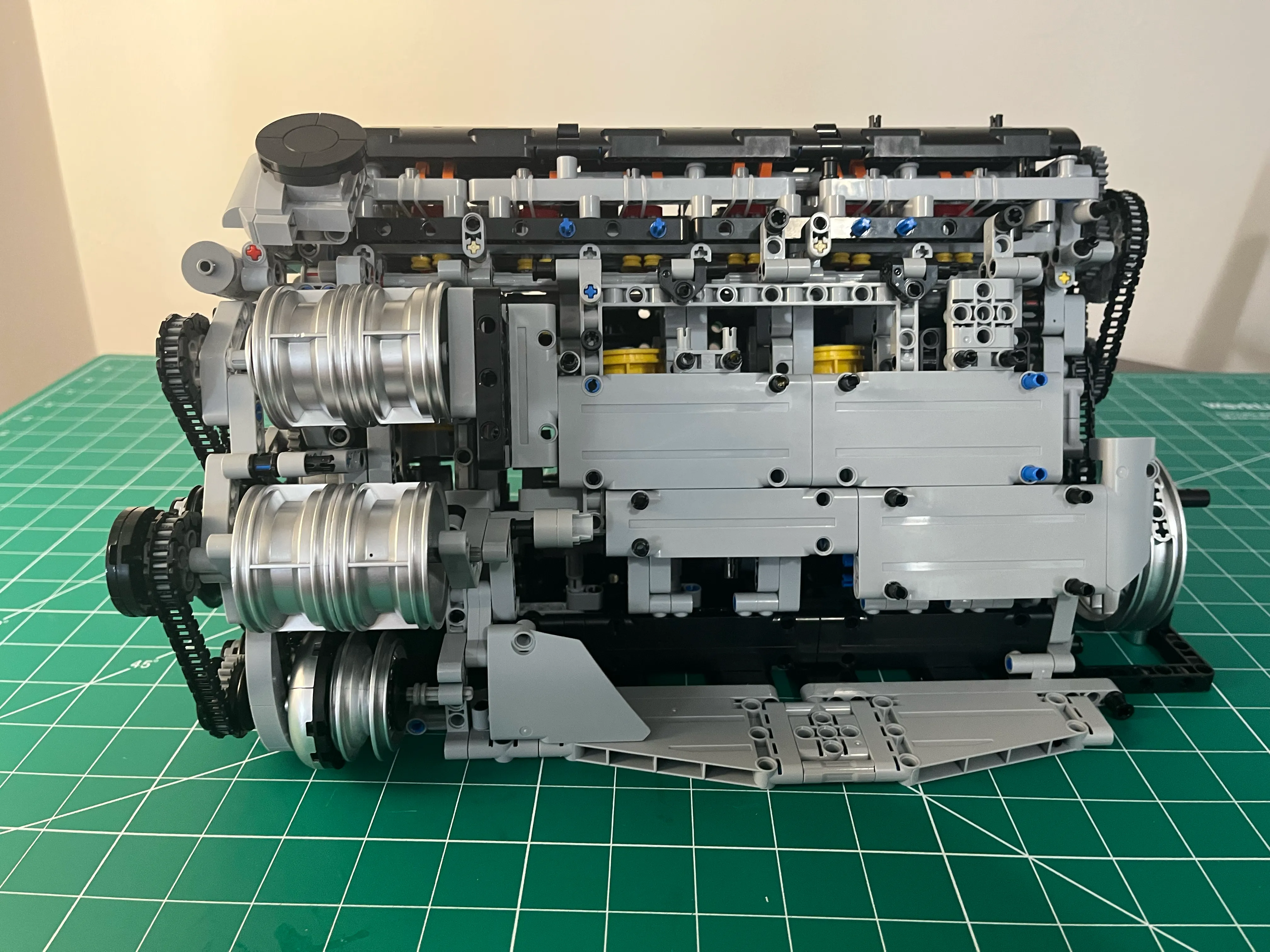
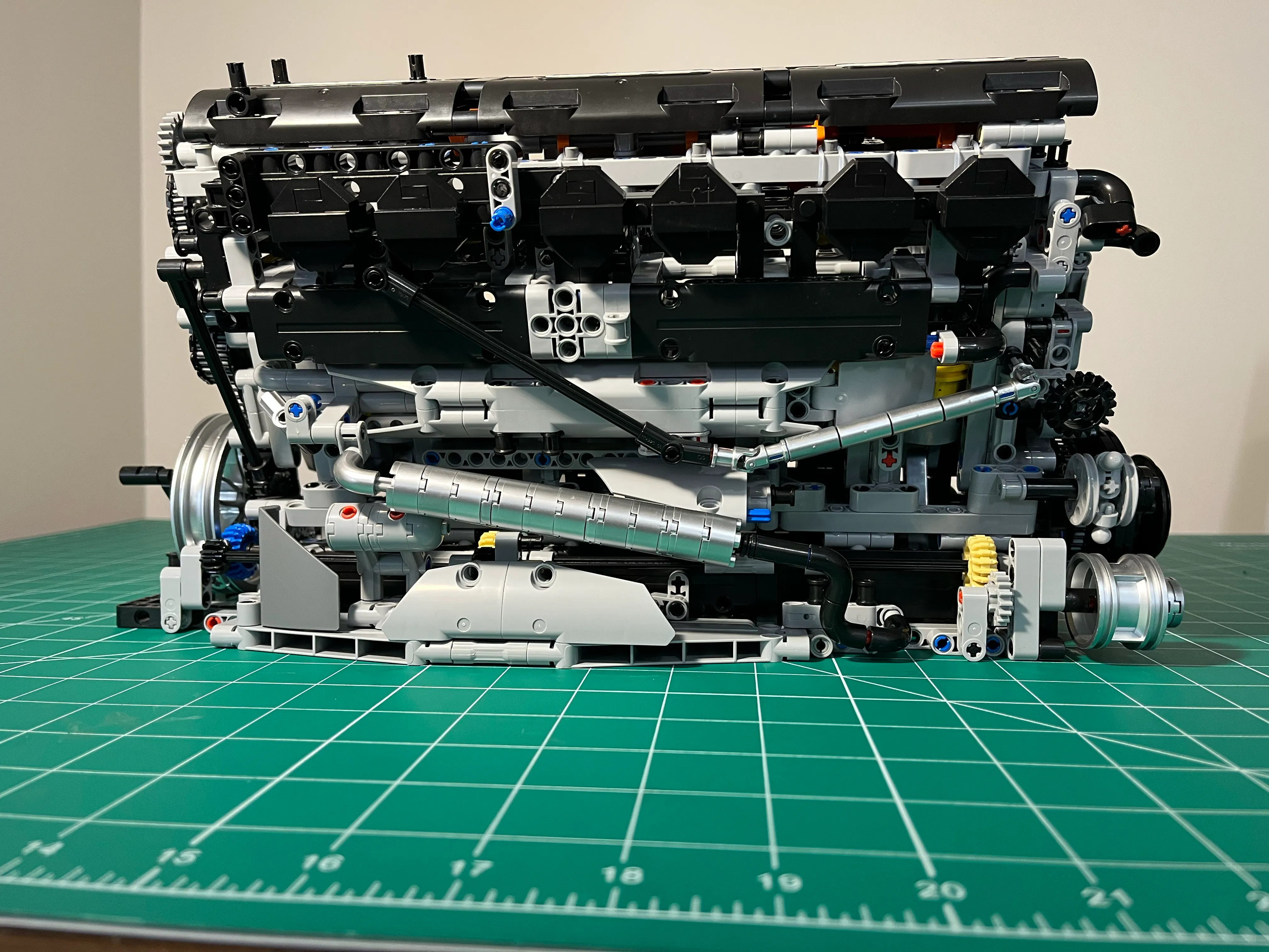
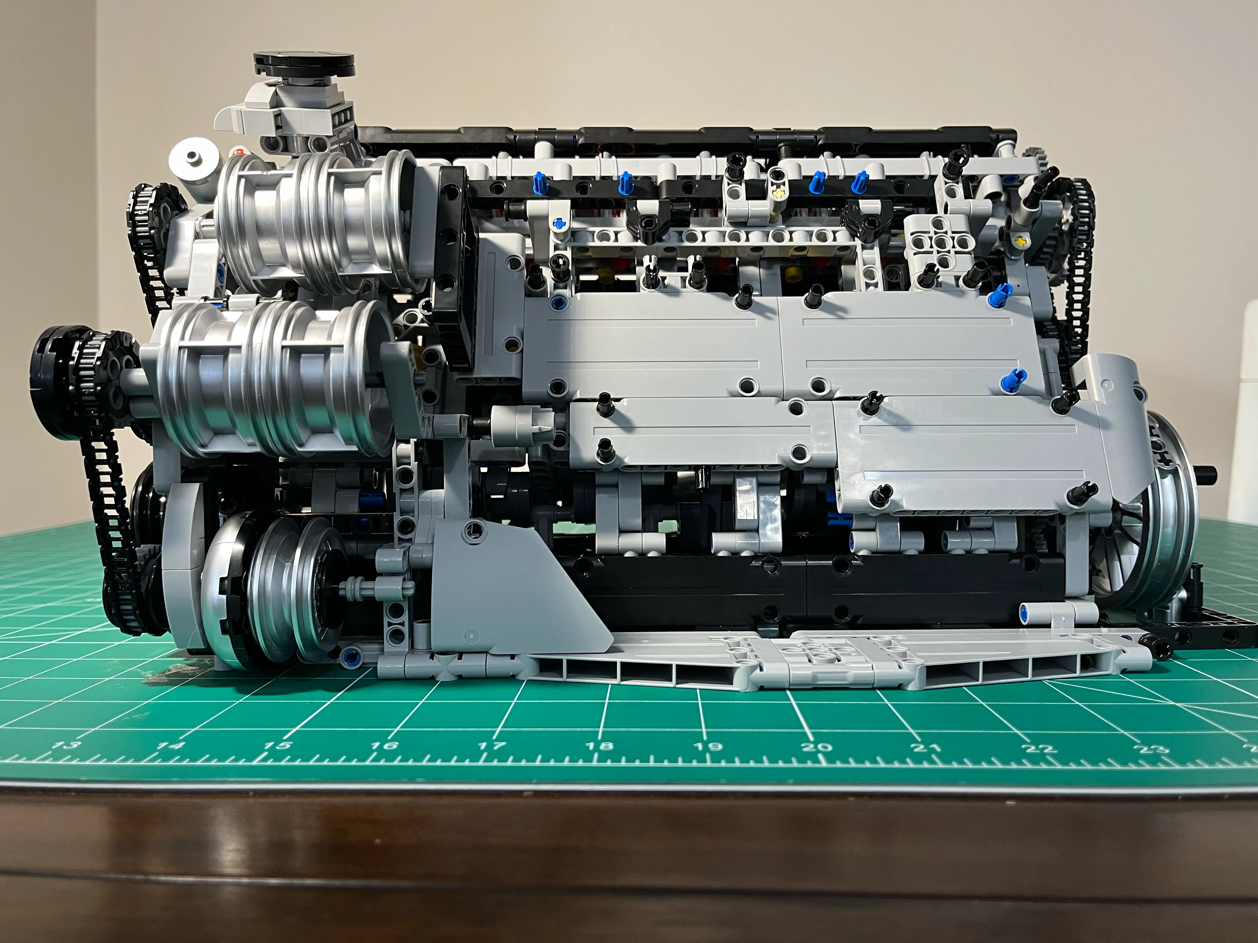
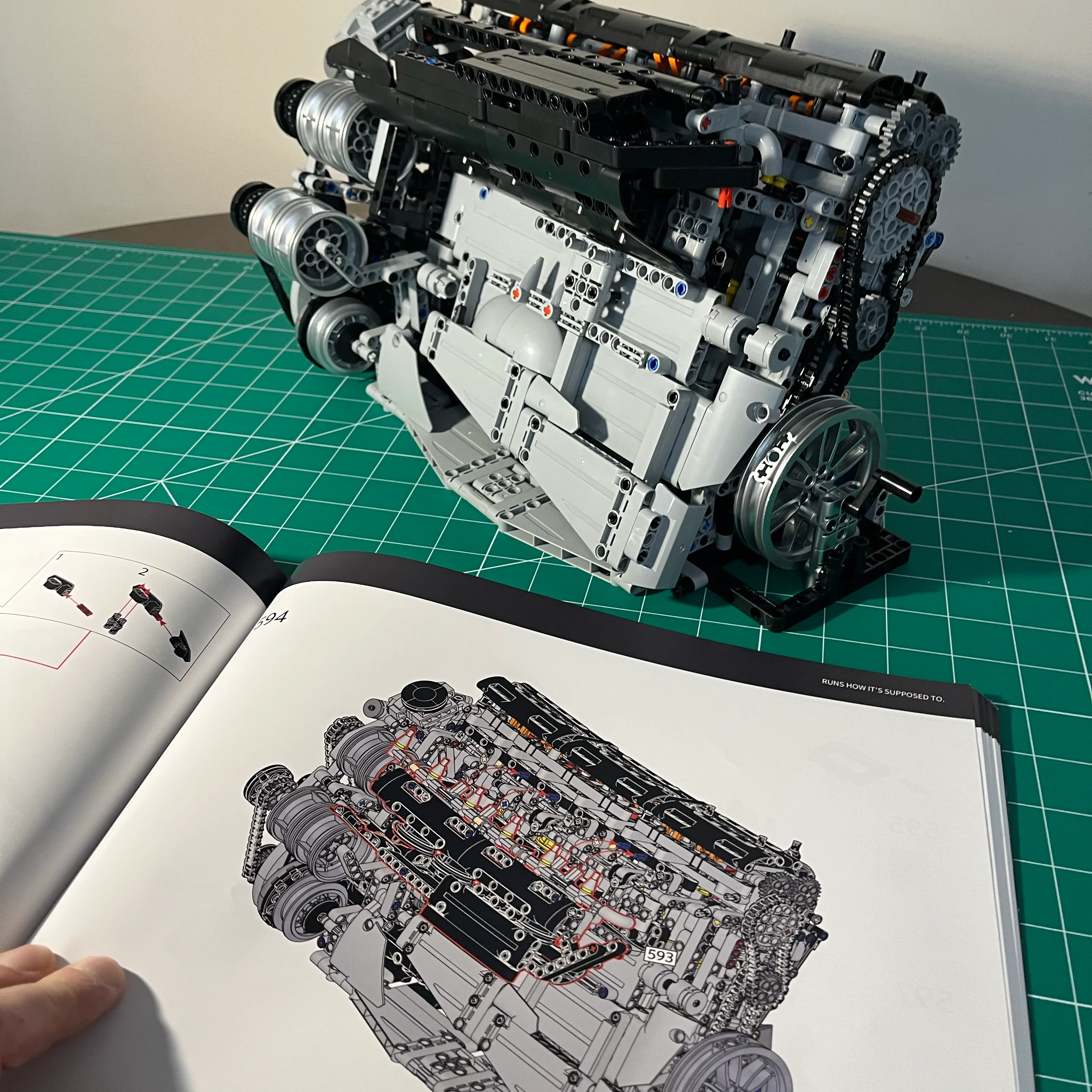
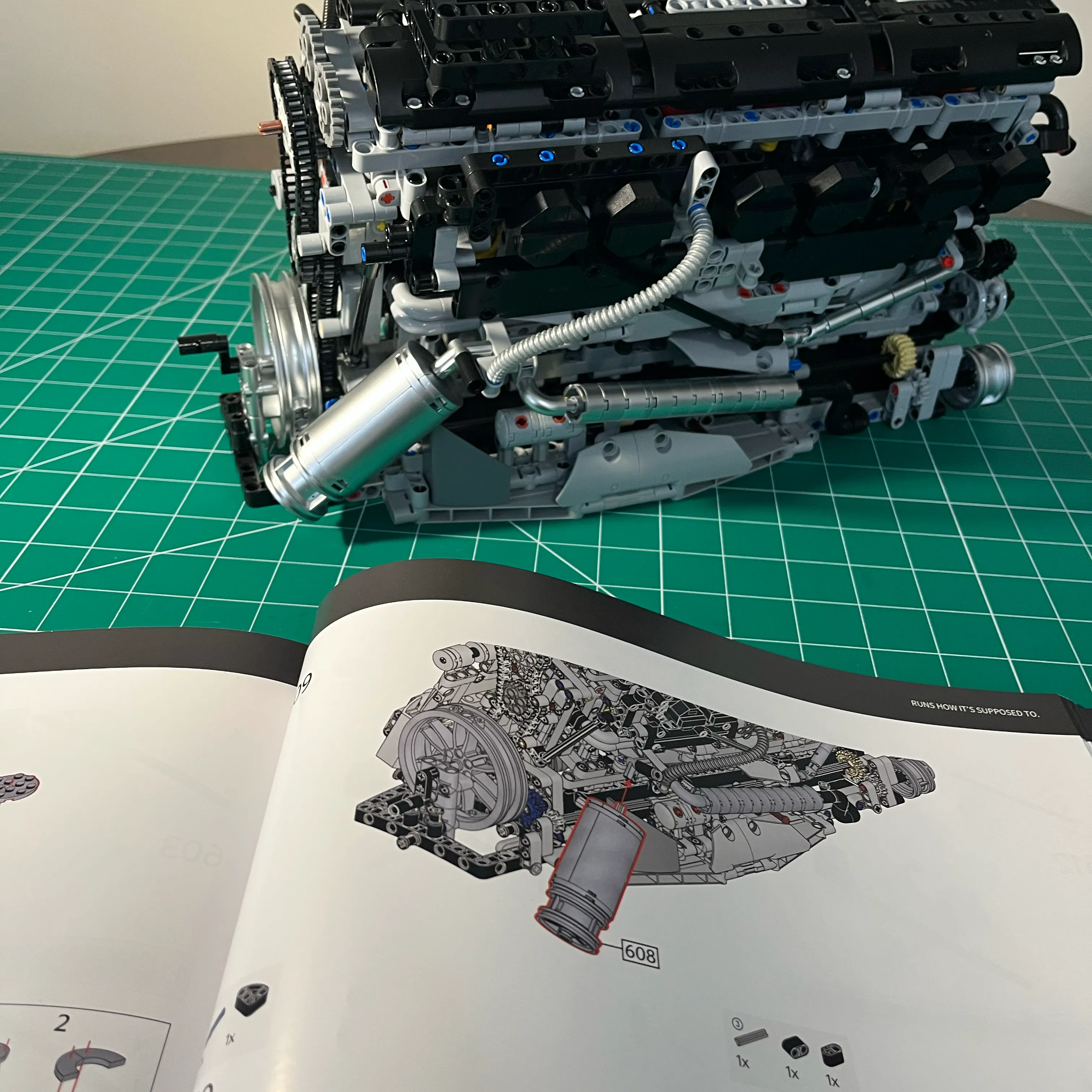
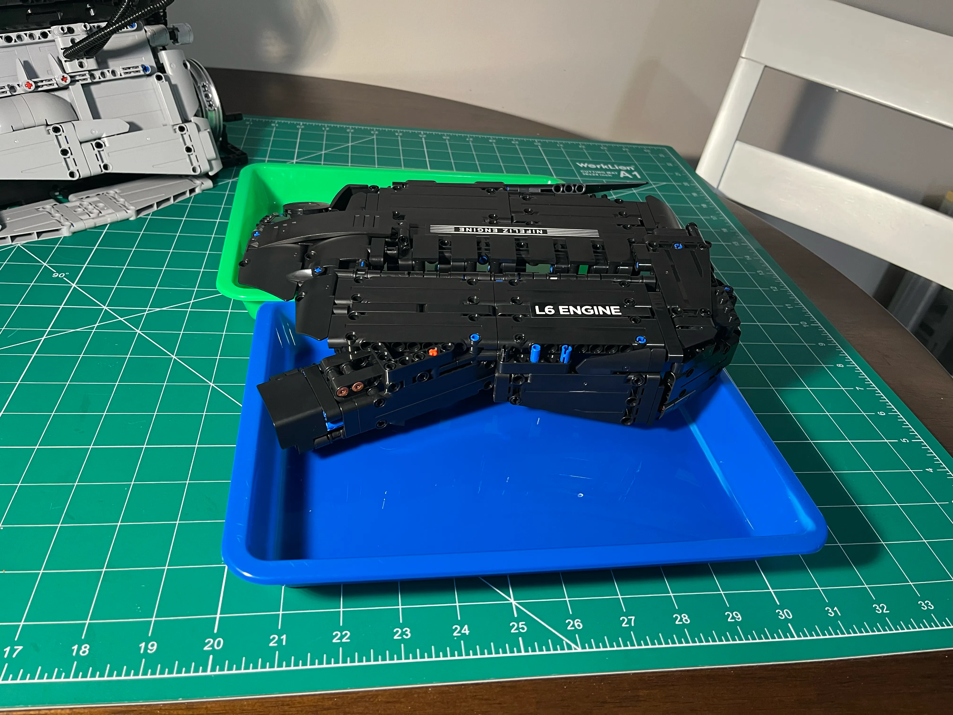
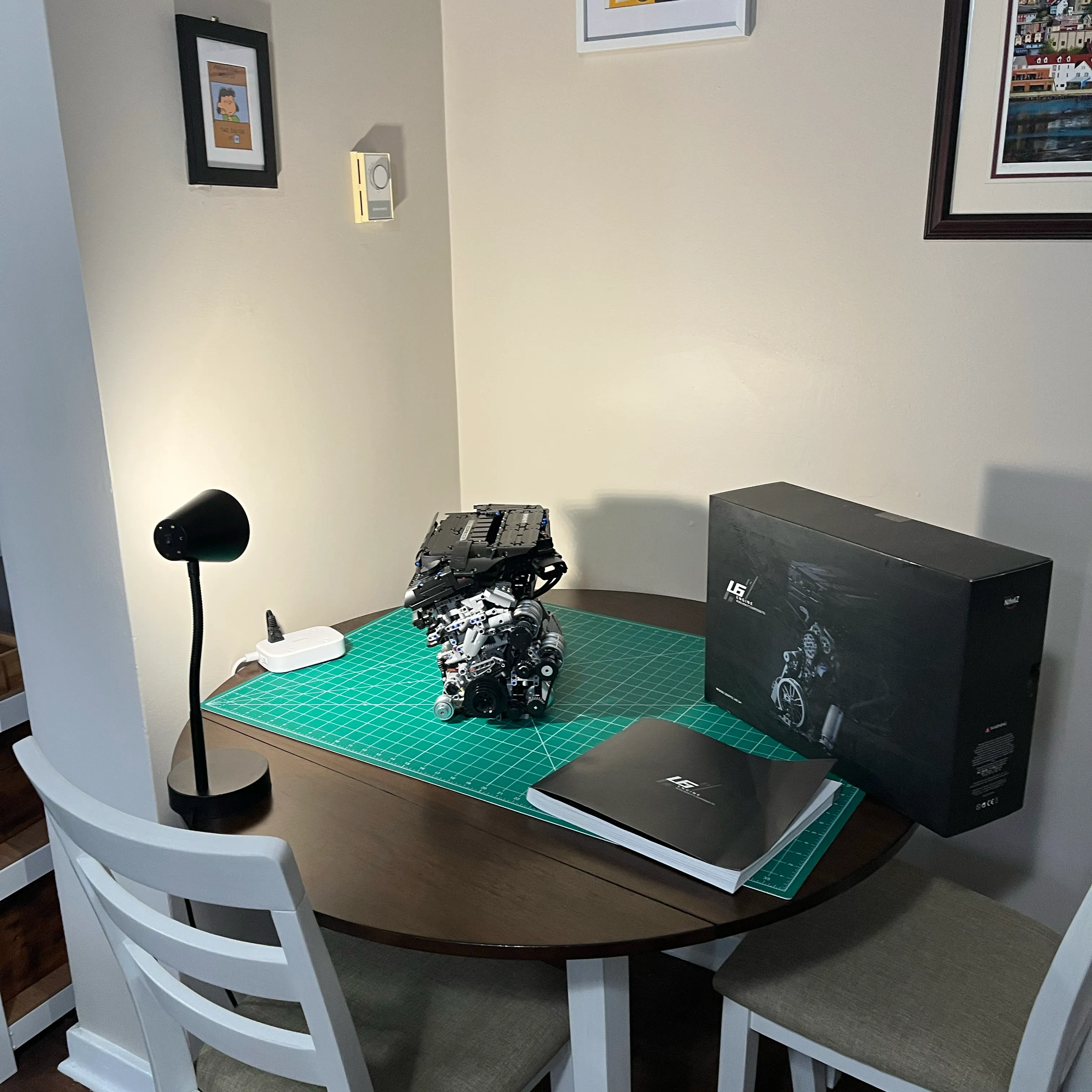
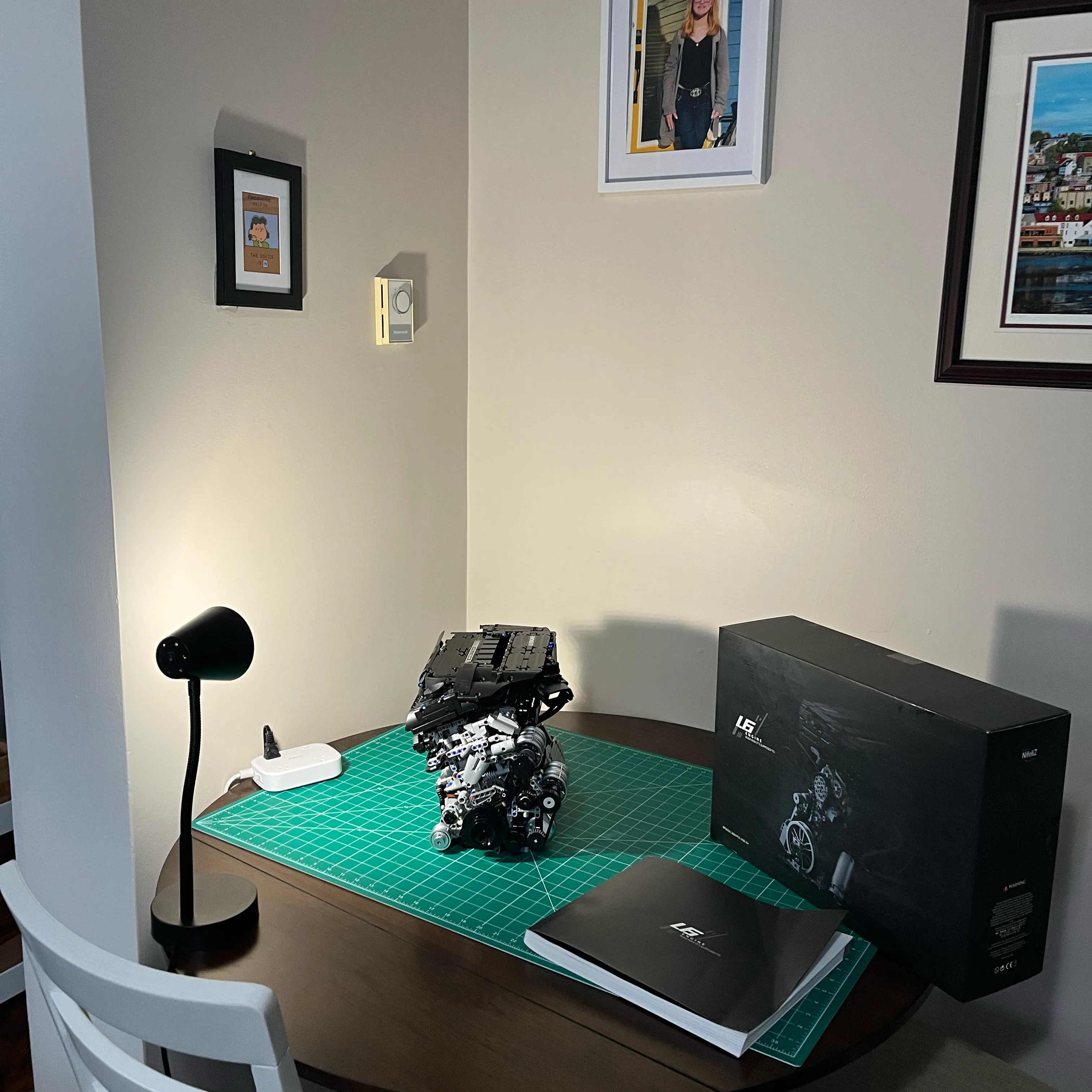
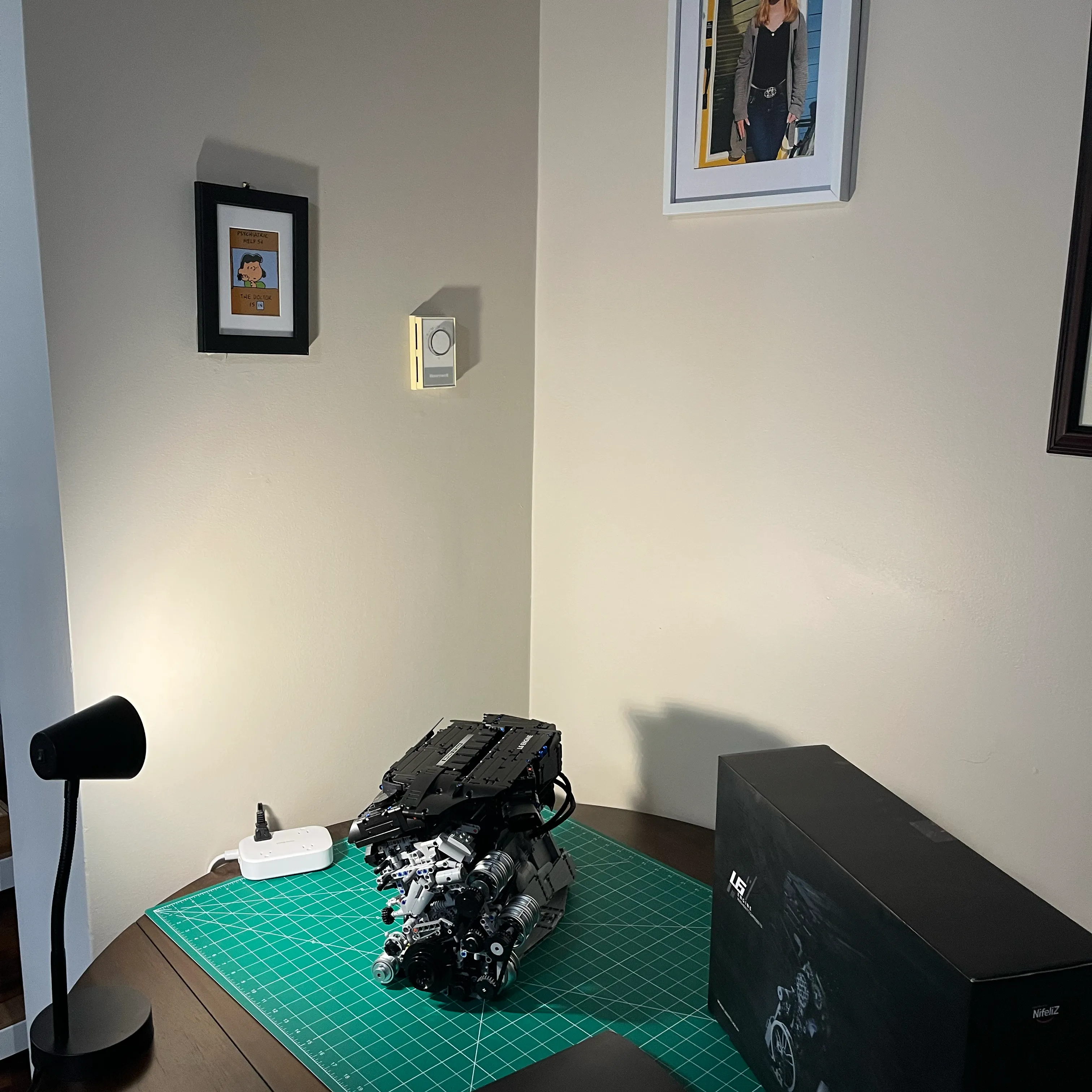
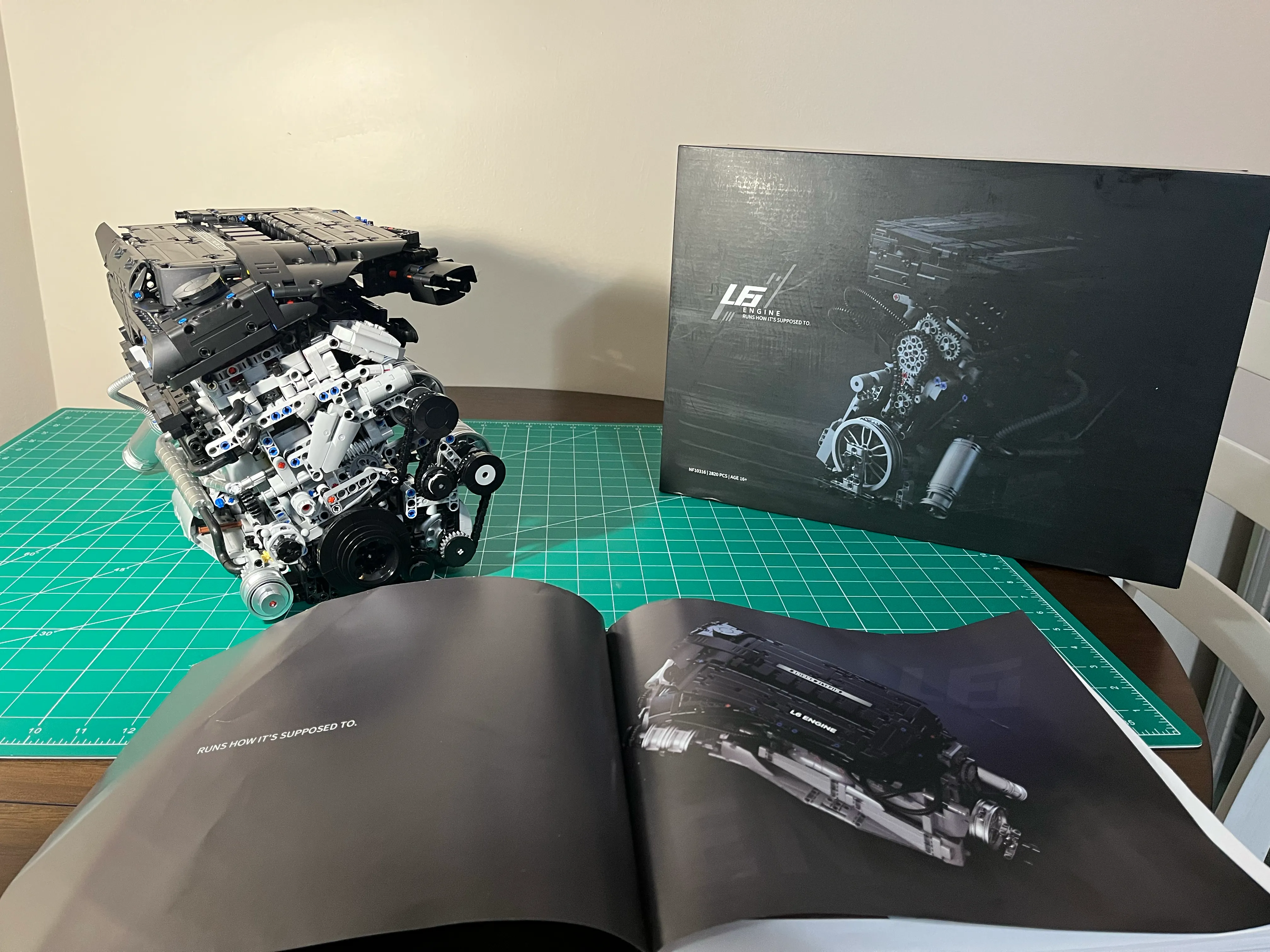
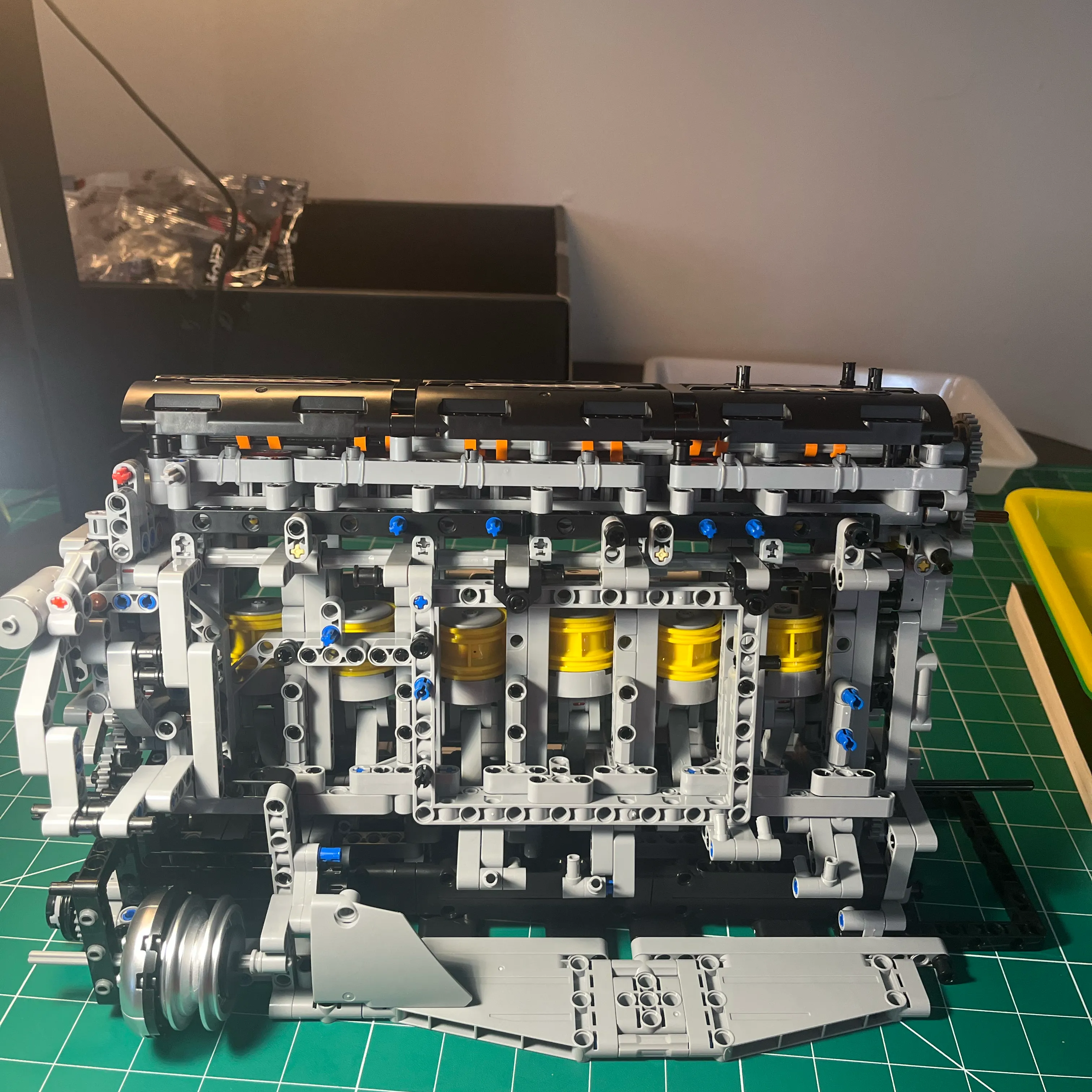
NifeilZ L6 Model Engine was a great building experience. I enjoyed the build, for the most part. The engine looks great. It’s a decent size too: 15 inches long, 7 inches wide, 10 inches high. The front of the engine has several accessories, including a turbo. It’s a realistic looking engine.
Fit and Finish Issues
Knots in Plastic Hoses
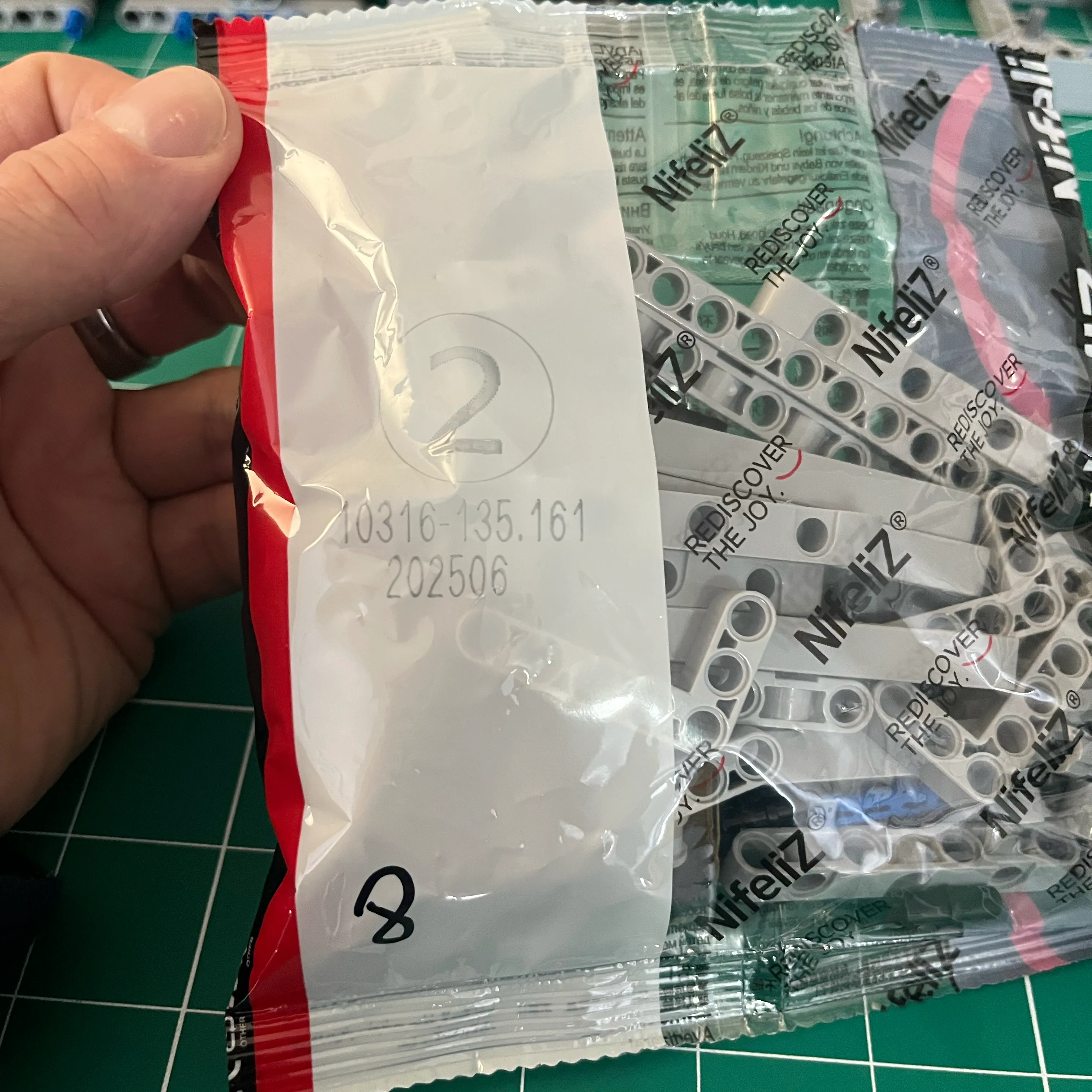
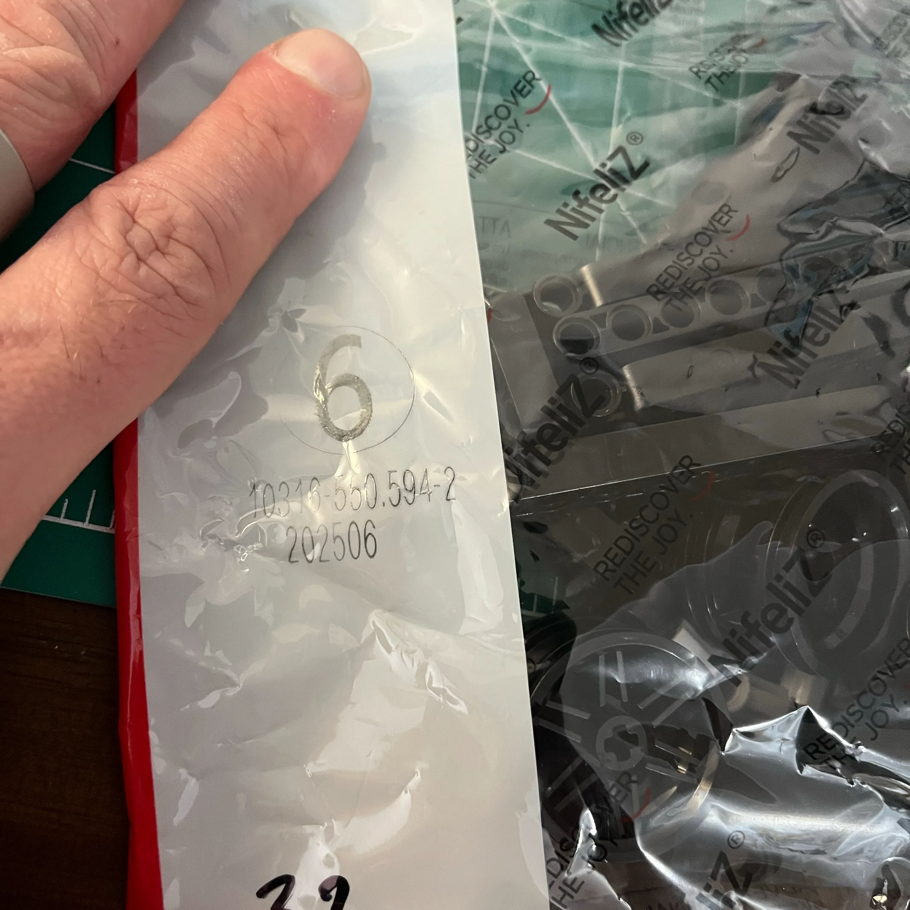
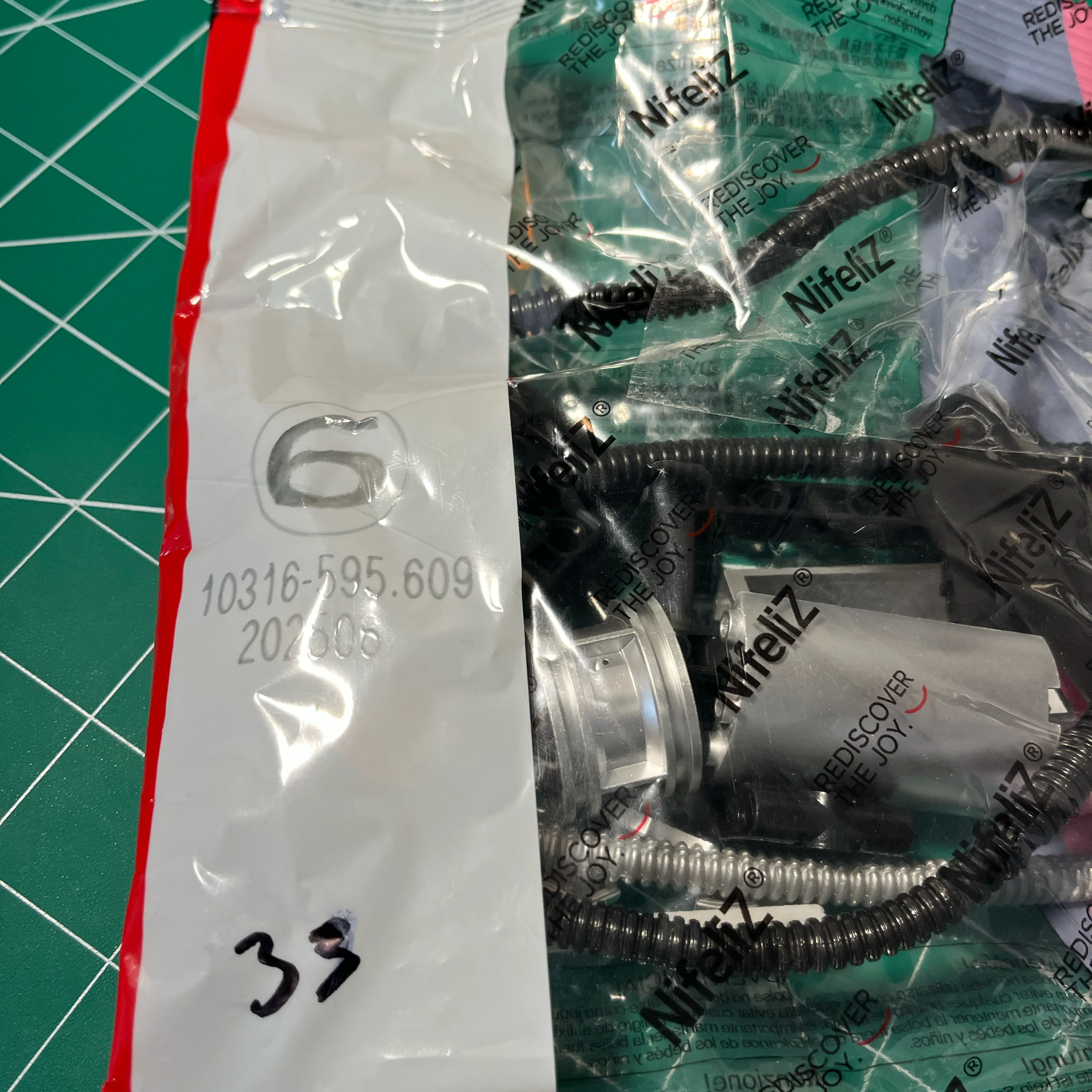
The plastic hoses were tied in knots during packaging, which detracts from the look of the engine once the knots are undone.
Engine Cover
The engine cover is really nice, and I don’t want to just let it sit on top of the engine. It doesn’t look great when the engine cover is not level. Any bump and the engine cover can move.
I was pissed that the nice engine cover that is the final part of the build does not include any mechanical fasteners. From what I can tell, the instructions tell you to just lay the cover on top of the engine. I could not believe it. I was able to find enough left over parts to rig something up, but it’s still not to my liking.
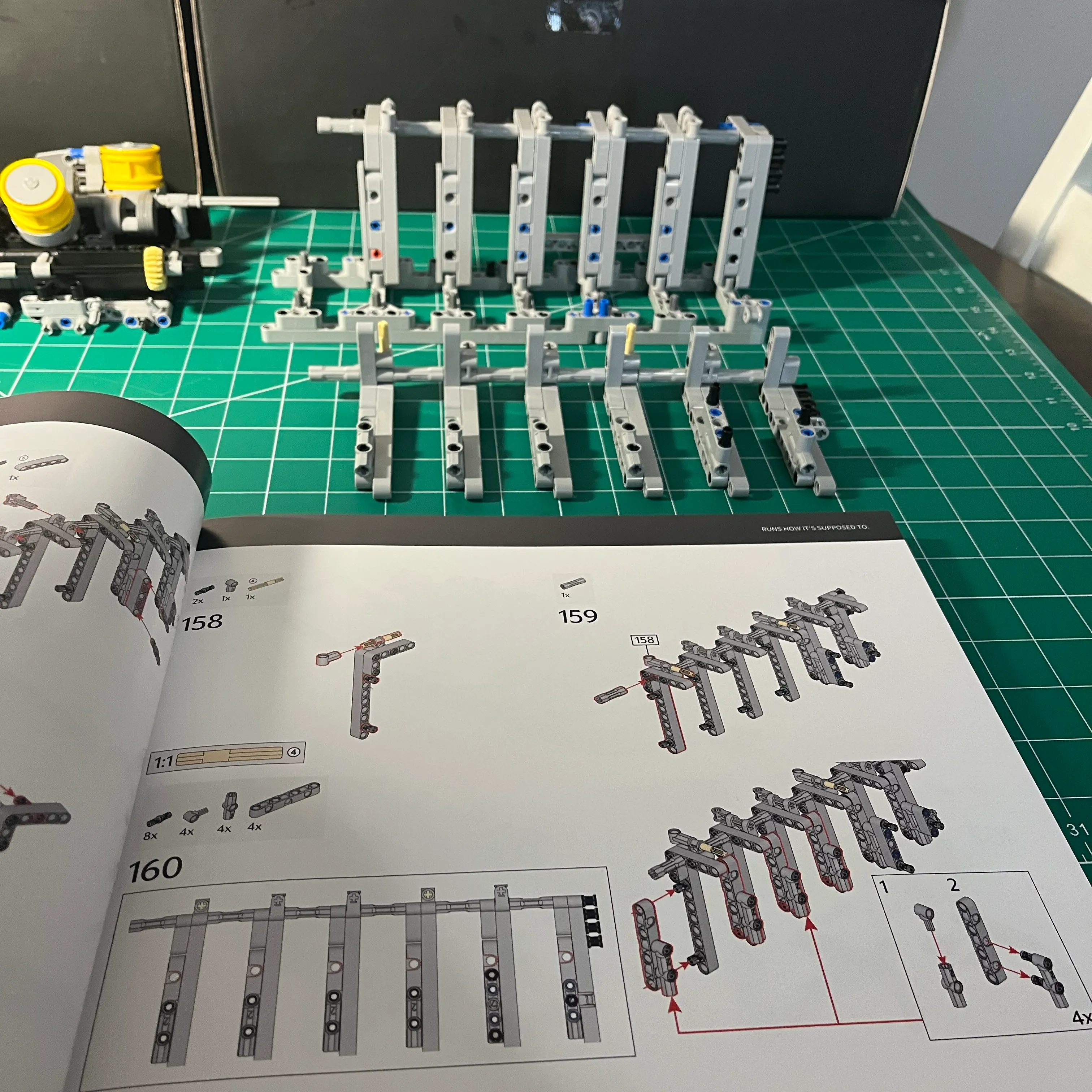
Crank and Piston Alignment / Clearance Problems
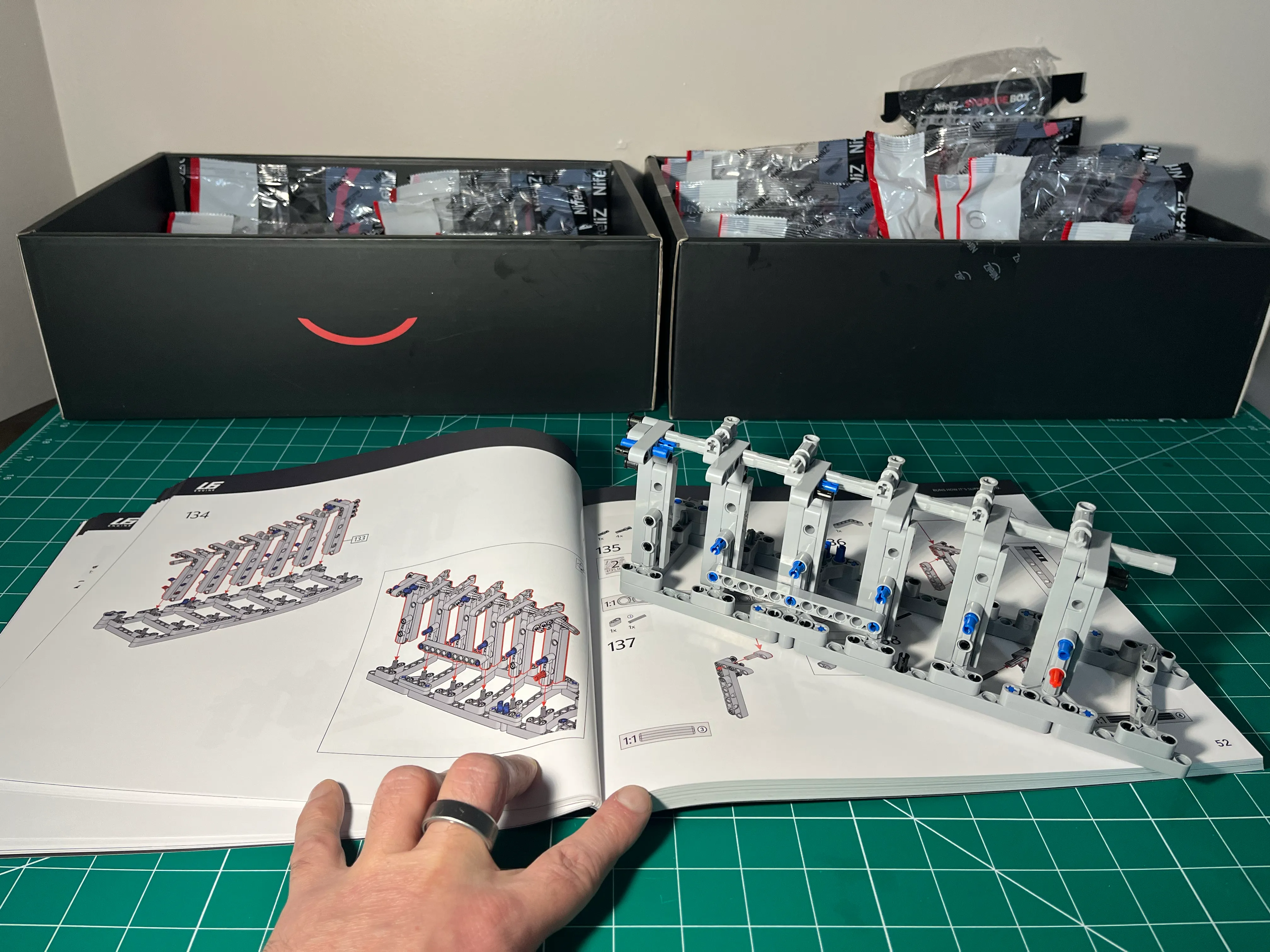
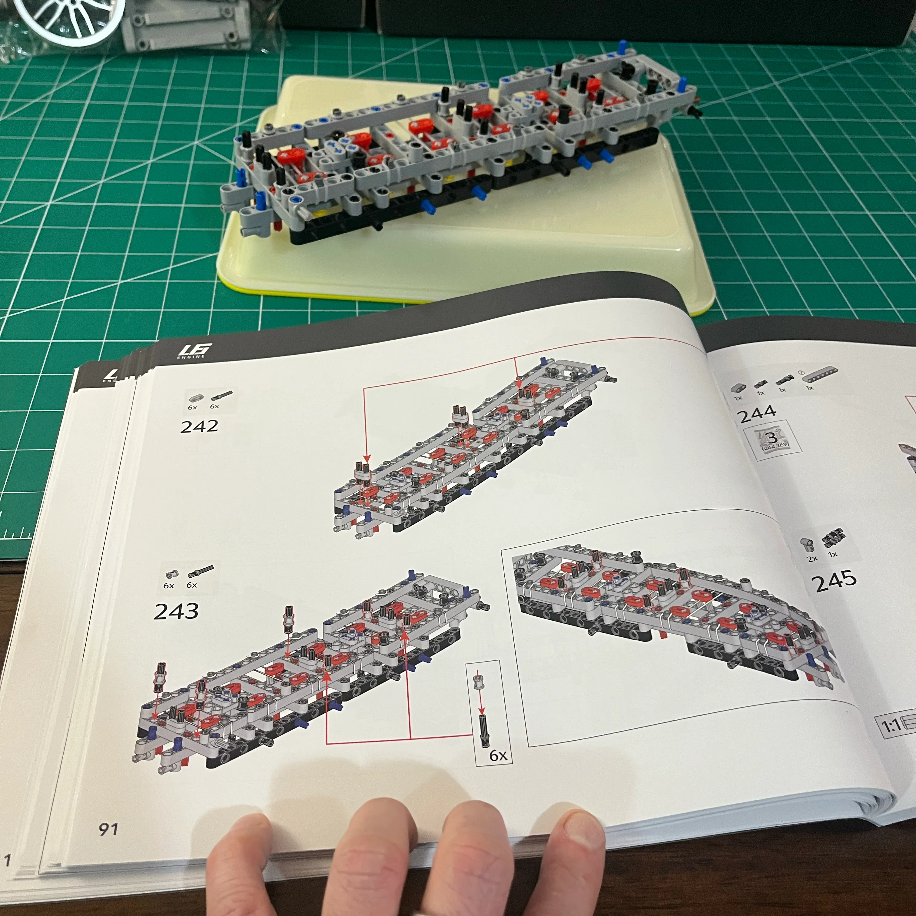
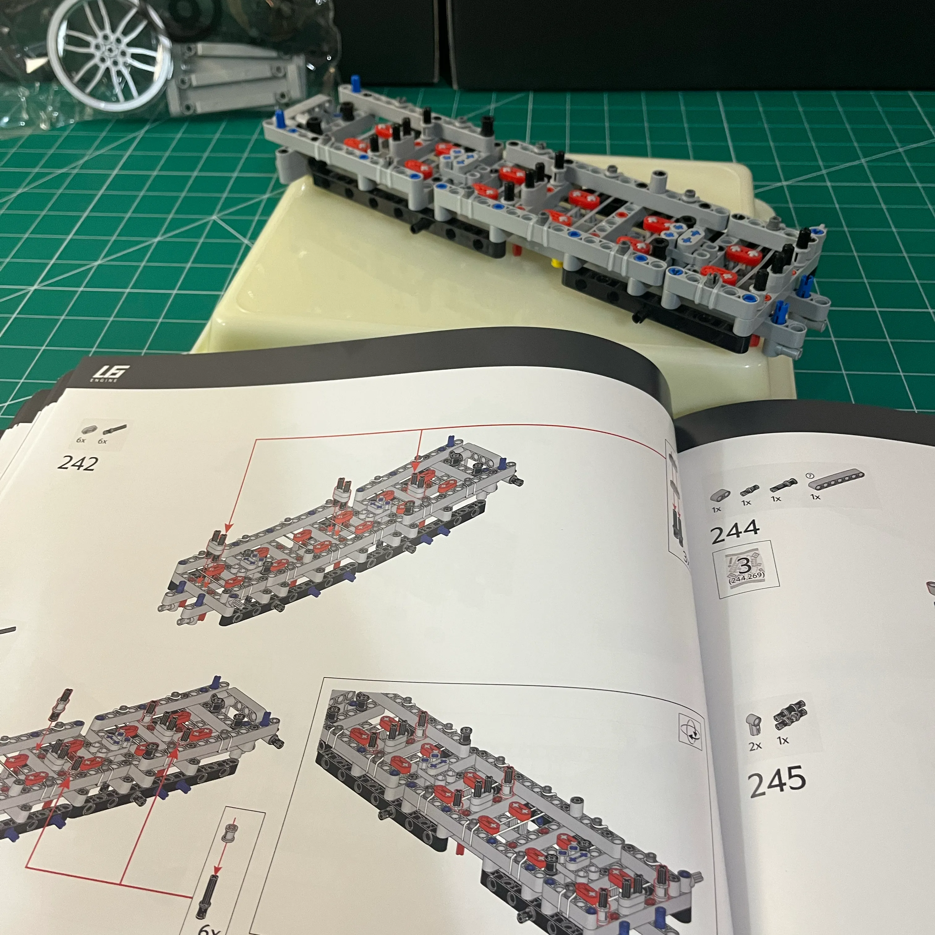
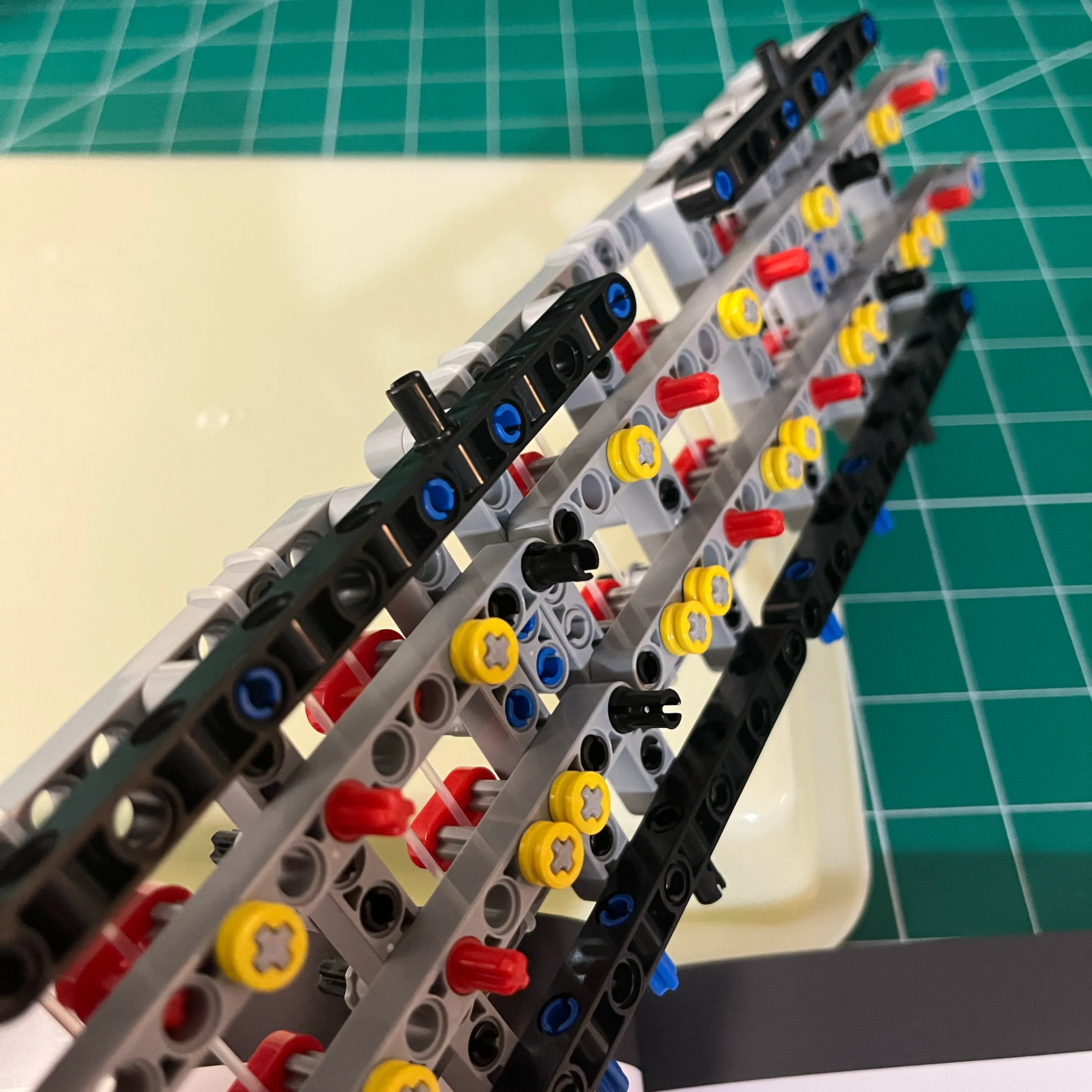
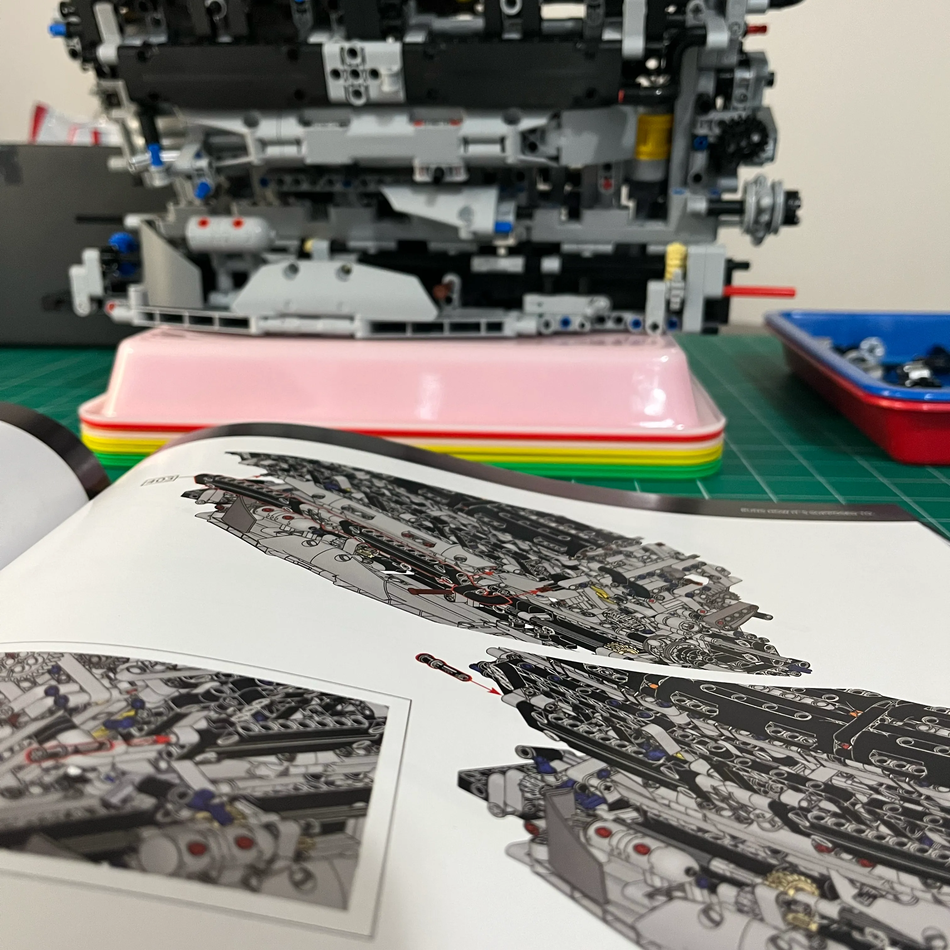
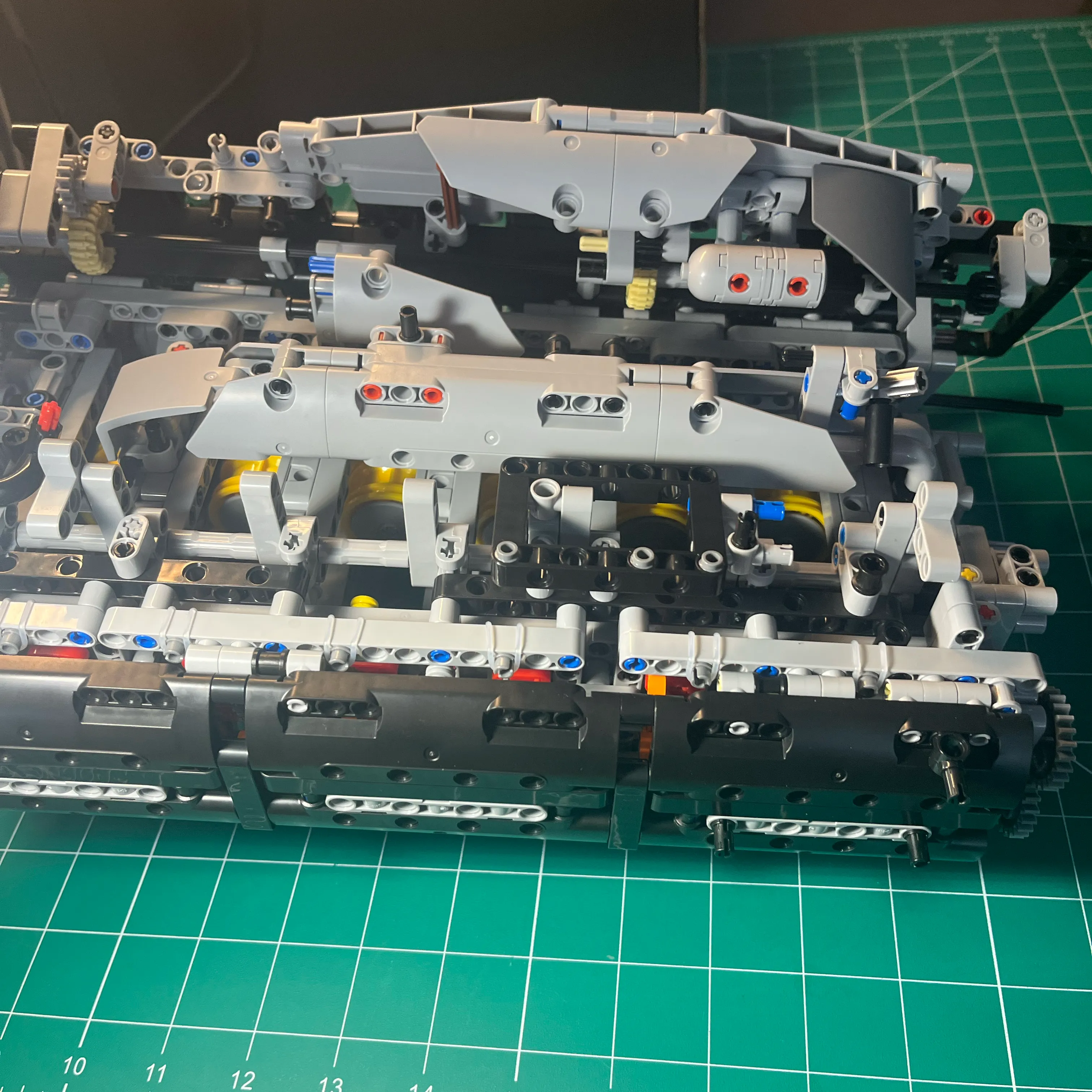
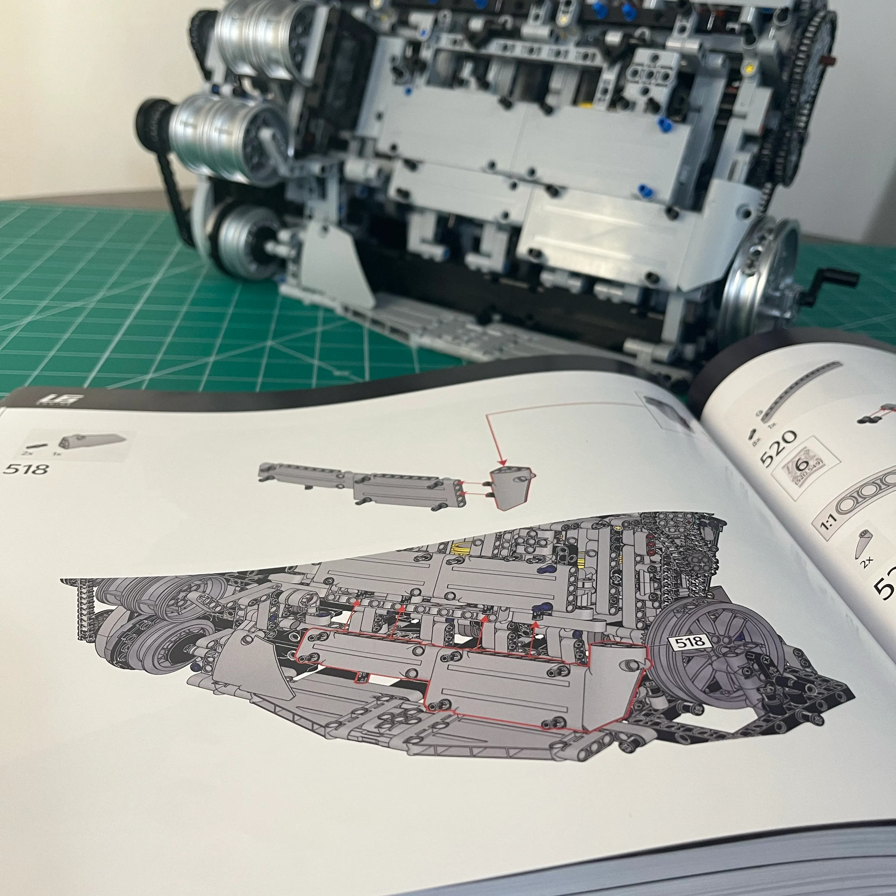
The assembly instructions did not go into depth on proper crank and piston alignment procedures. The existing steps have you assemble the crank and pistons and add it to the engine frame, then assemble the engine block and cylinder head, and install it over top of the pistons. By the time you get to the steps where the gears are added to the engine to allow spinning the crank inside the block, any alignment issues are nearly impossible to fix since access to the crank / pistons is now completely covered up and you have to strip away the cylinder head and all exterior engine components that are attached to the engine block so you can see the crank lobes. Even then, the bottom side of the engine has zero visibility of the crank. Visualizing the binding points was brutal.
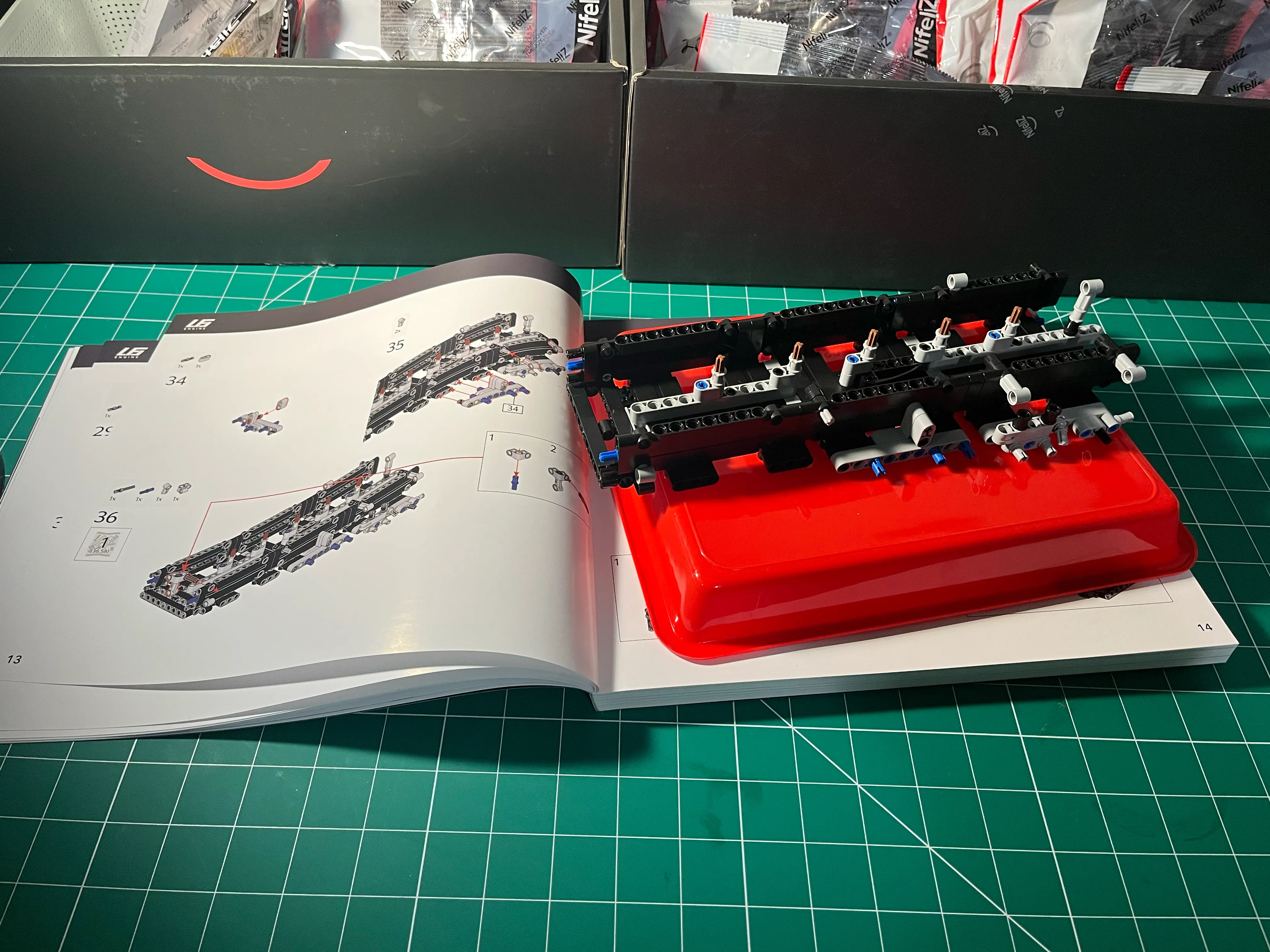
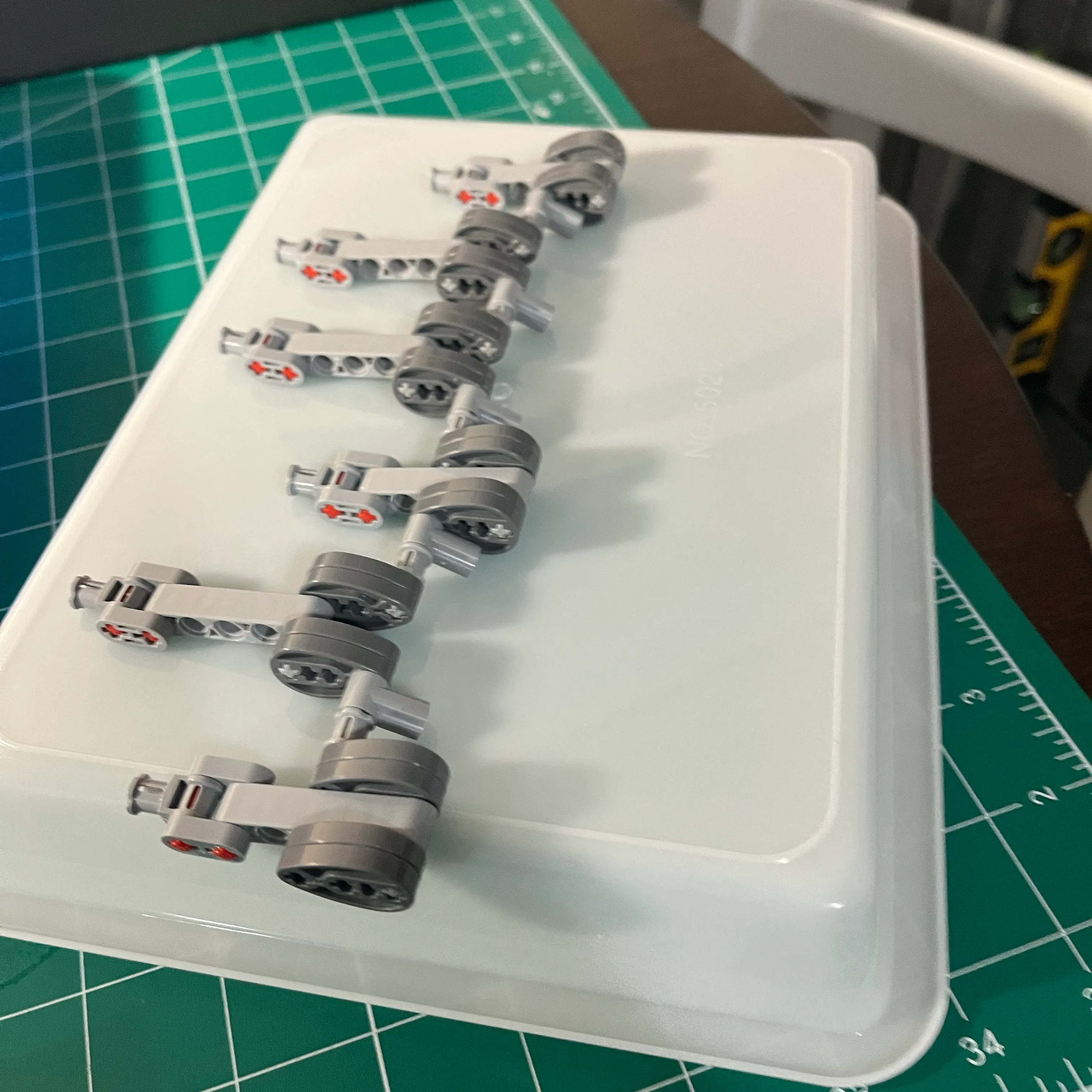
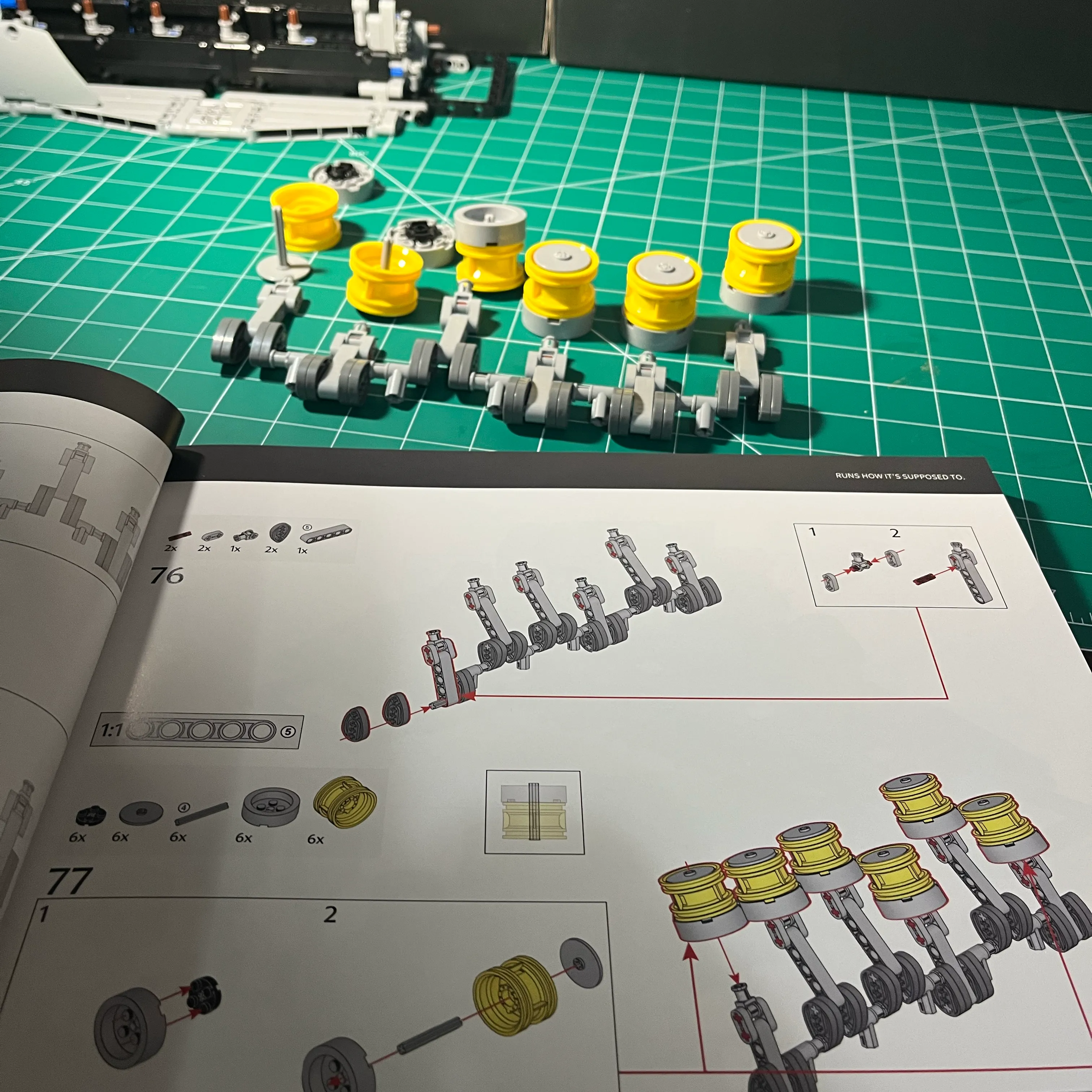
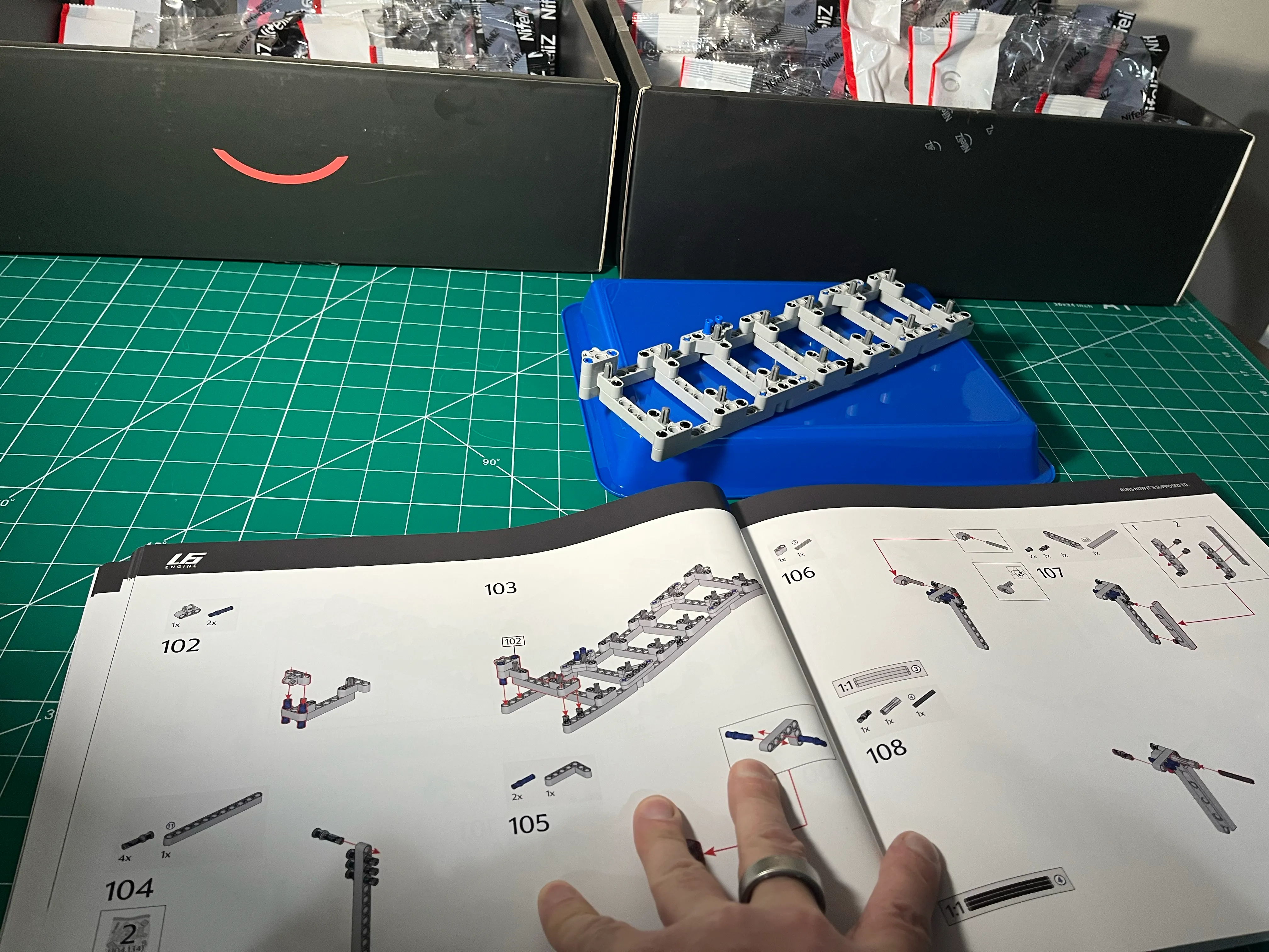
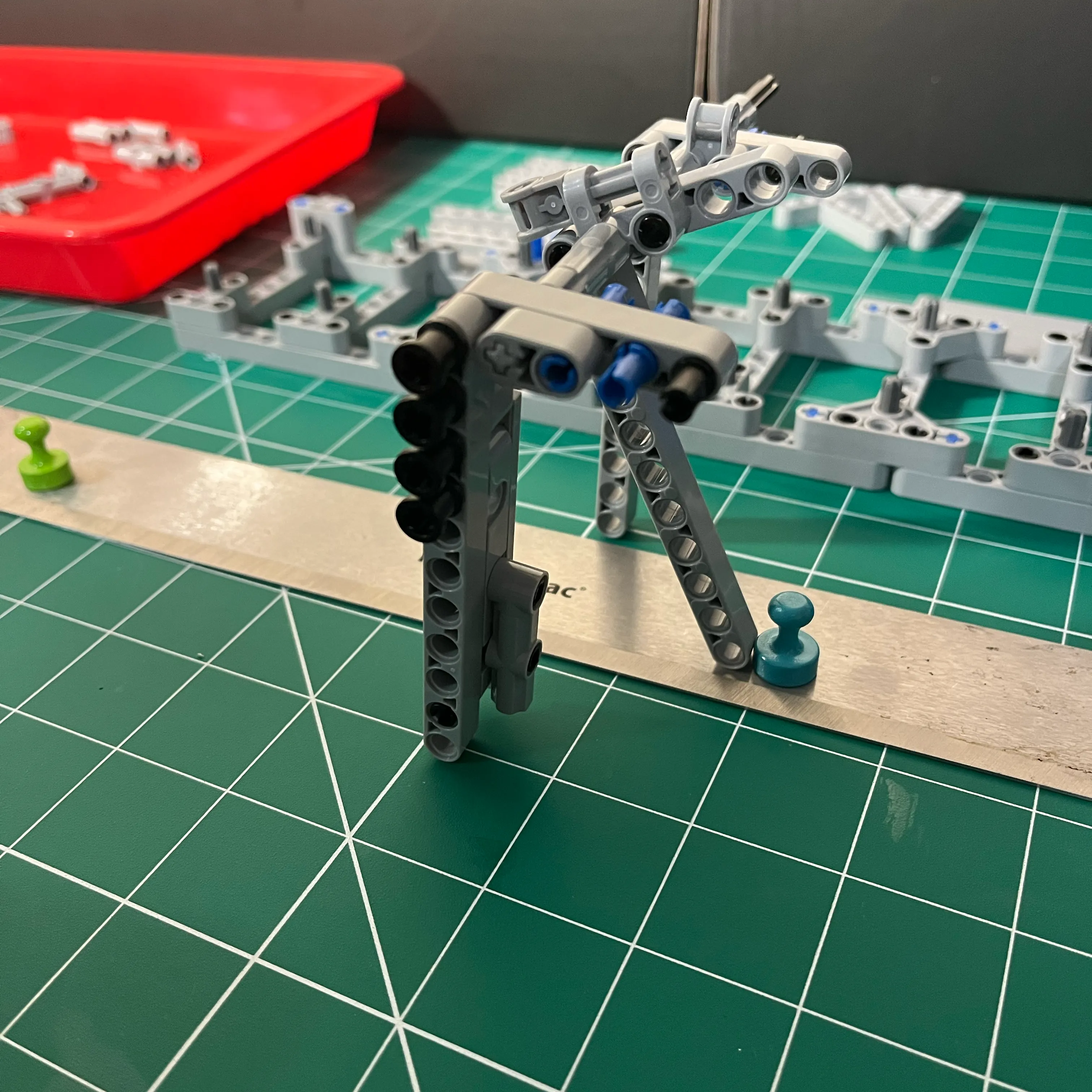
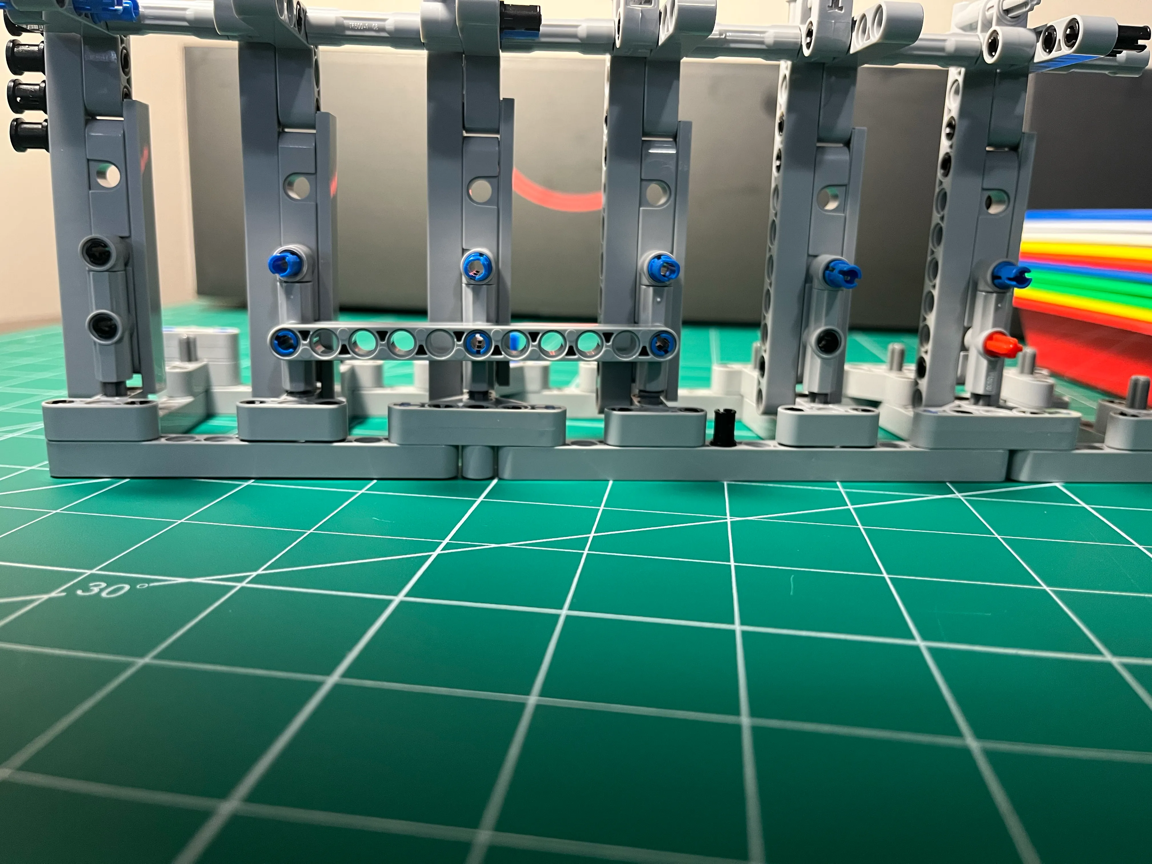
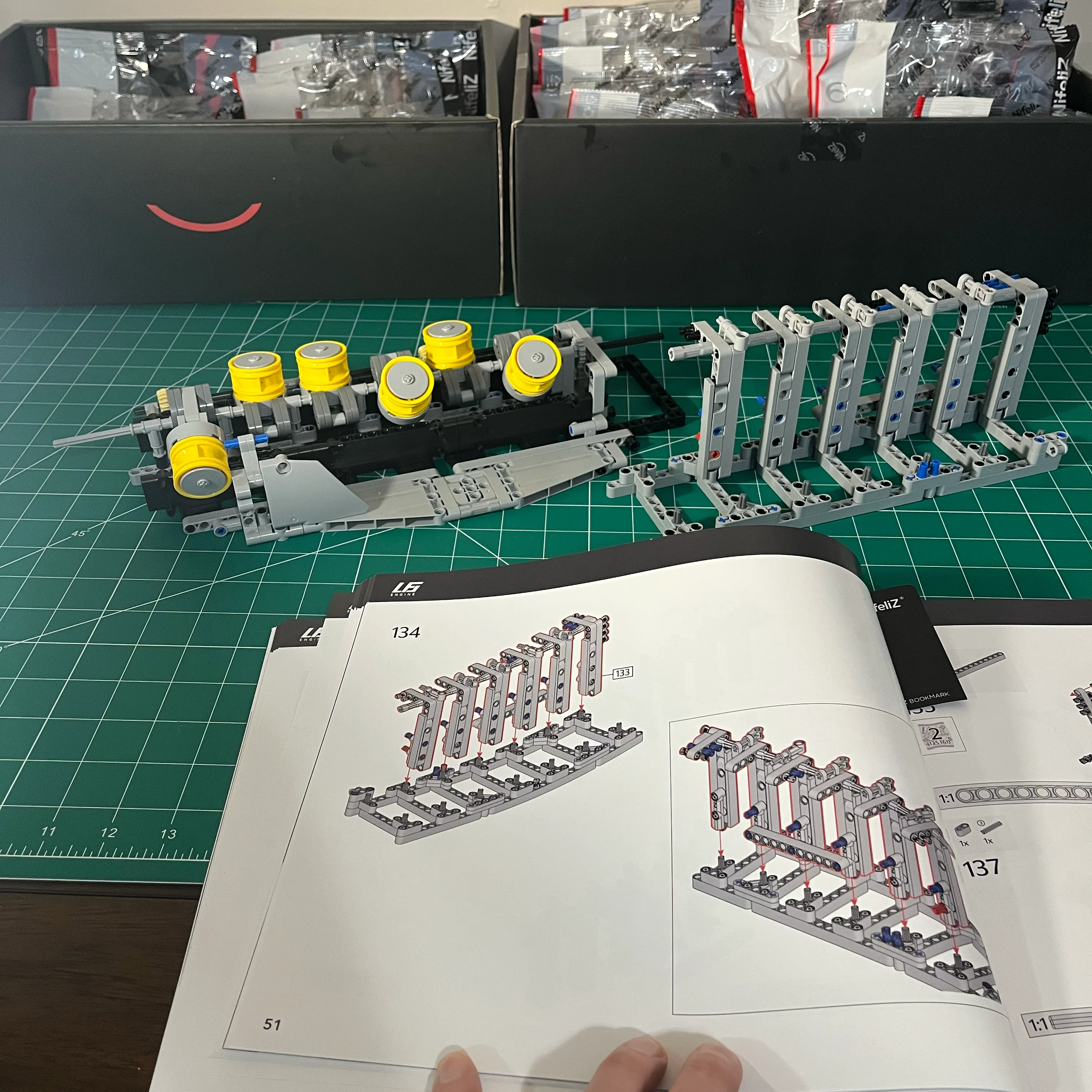
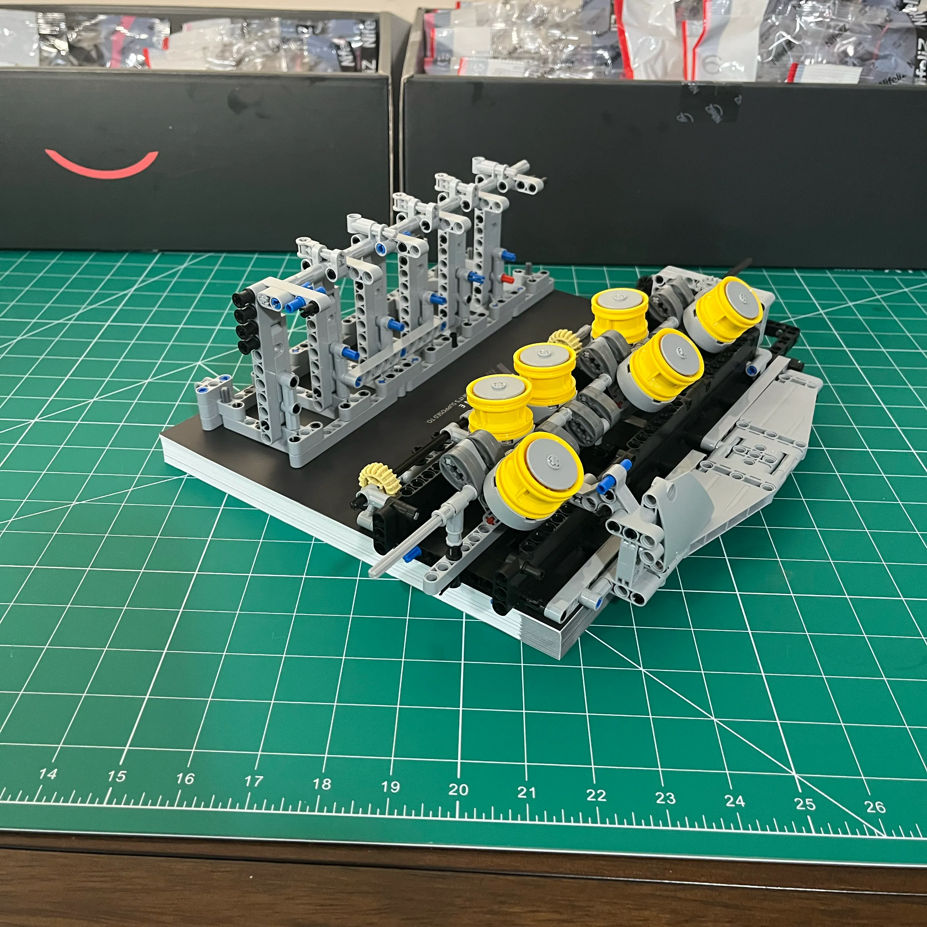
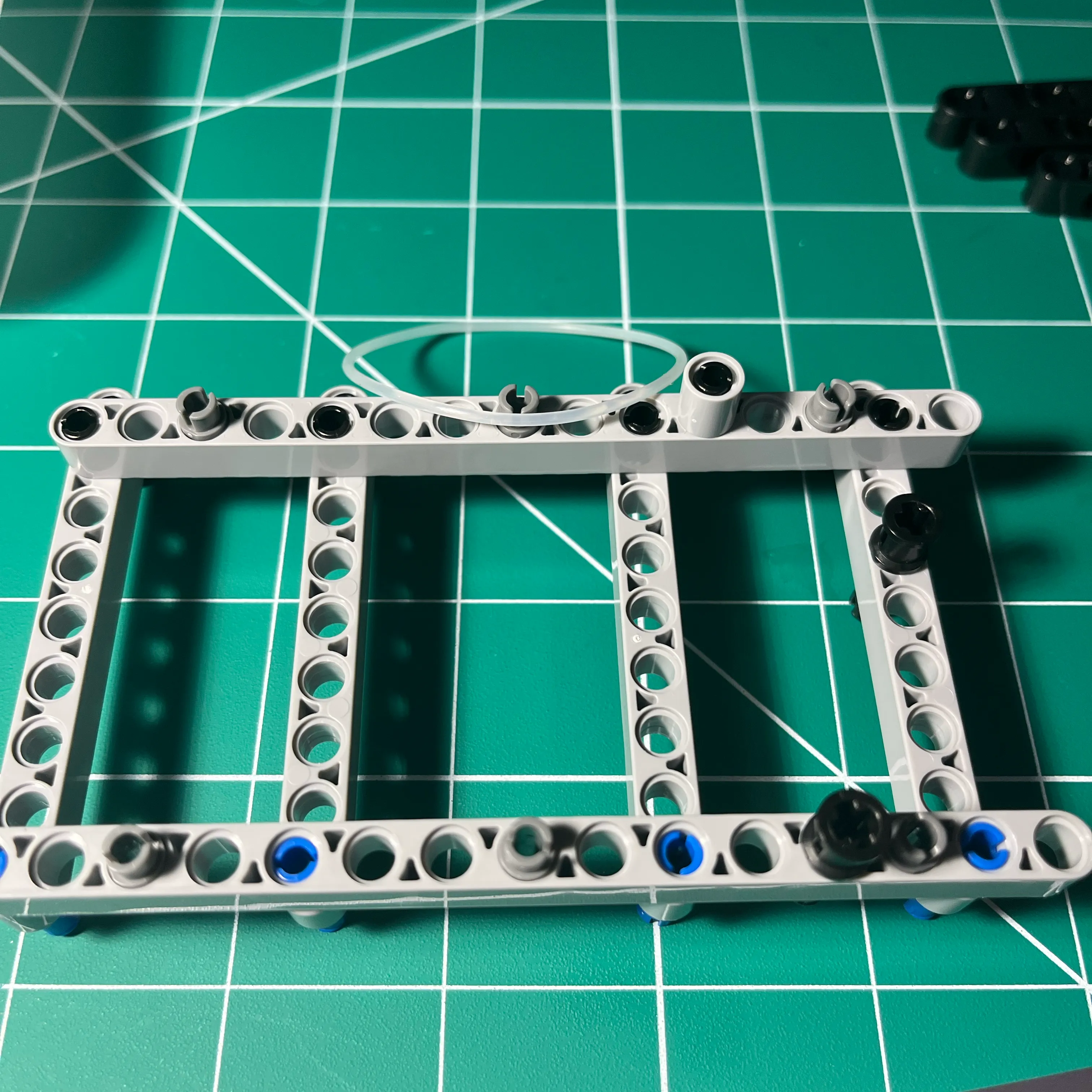
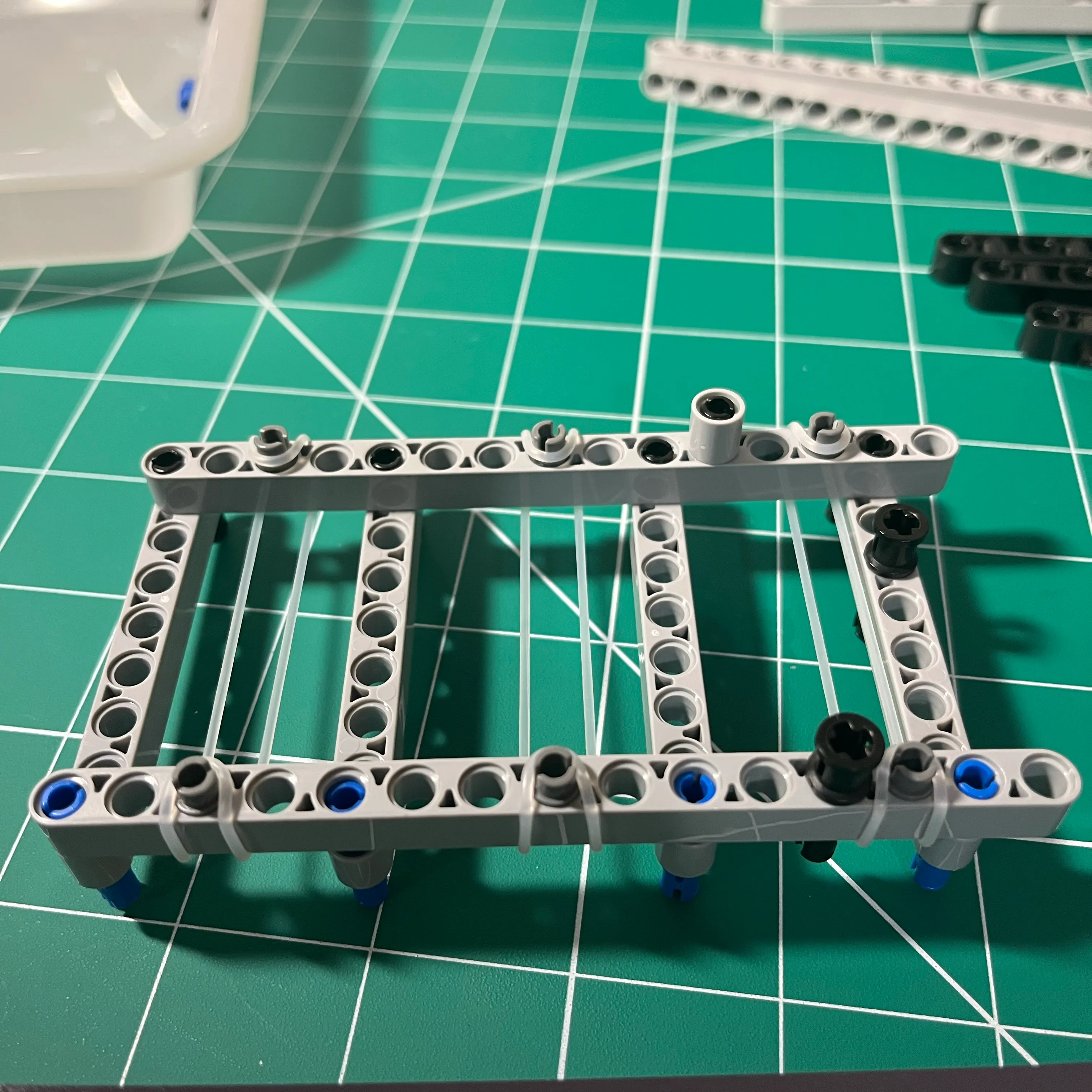
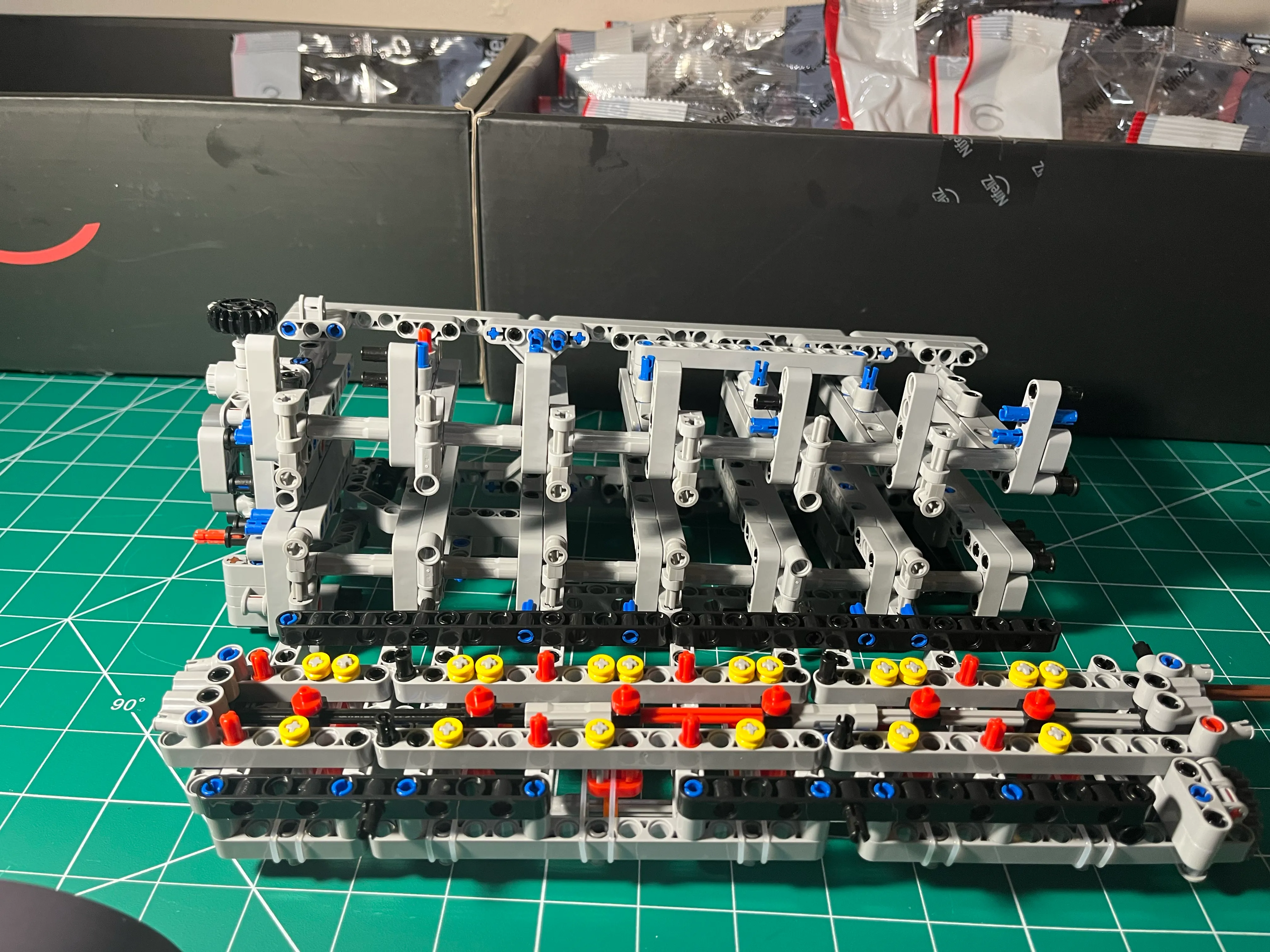
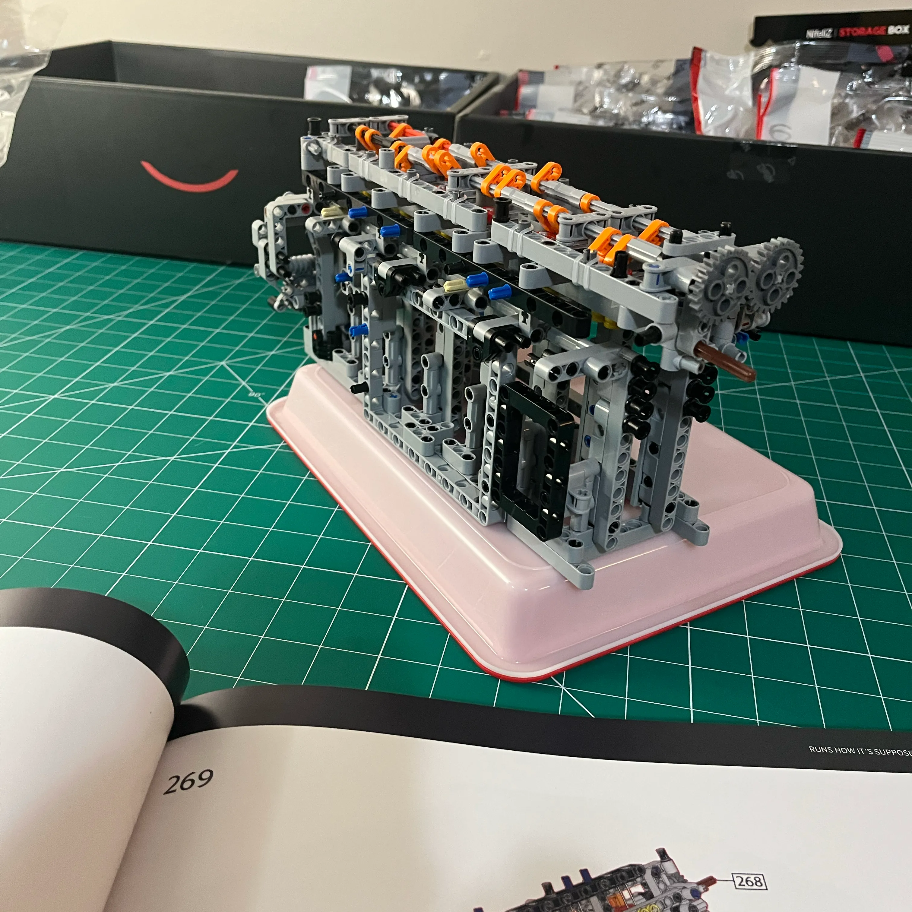
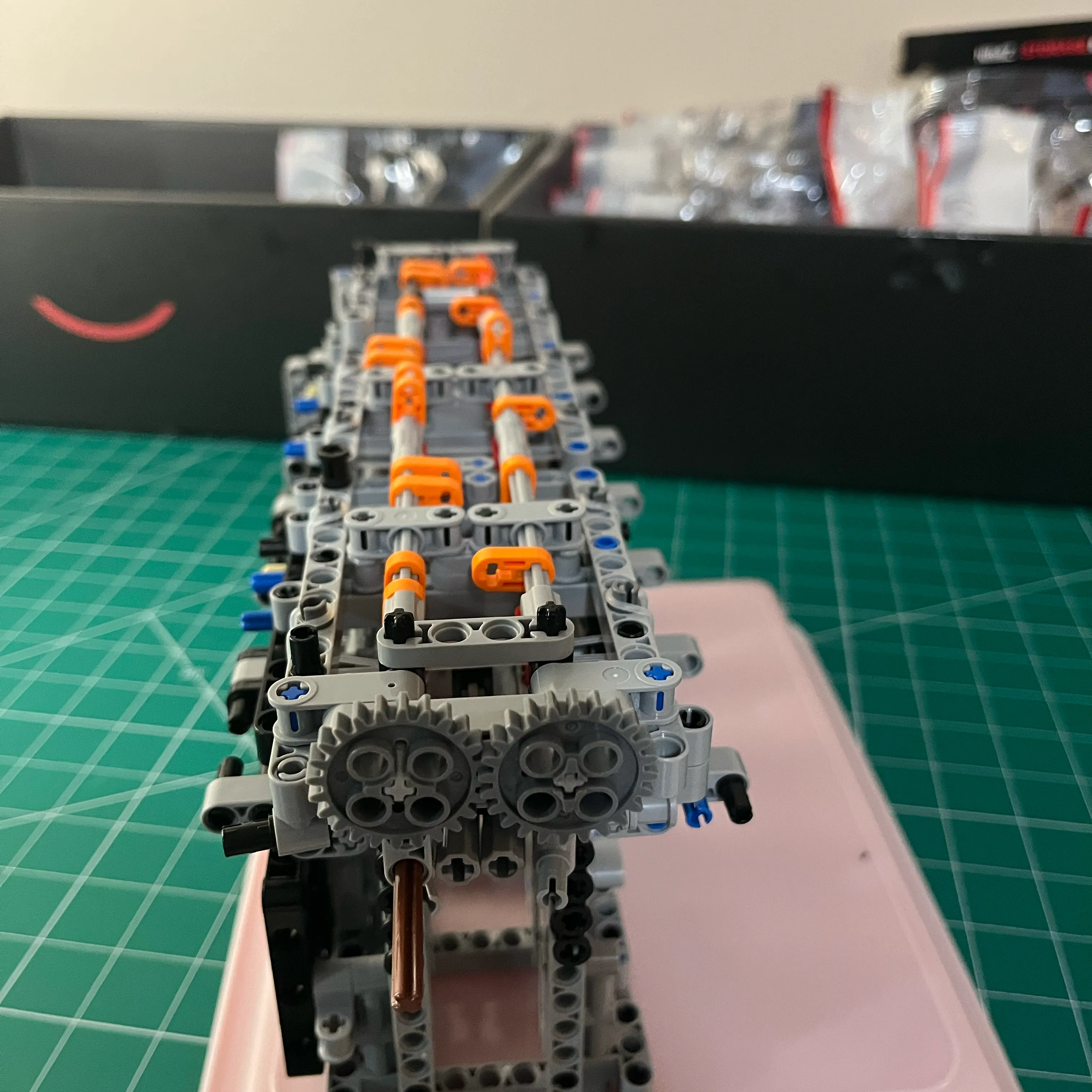
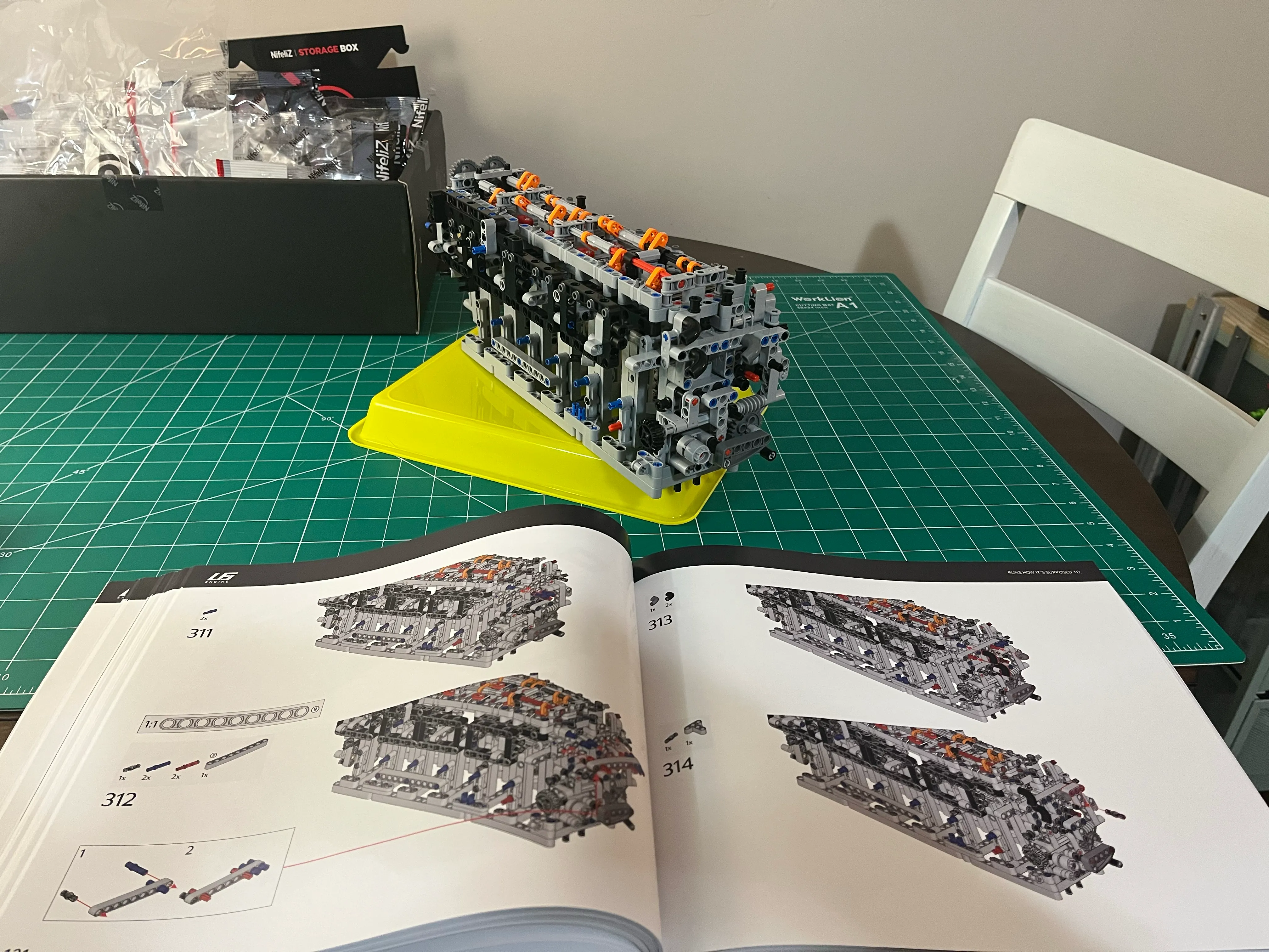
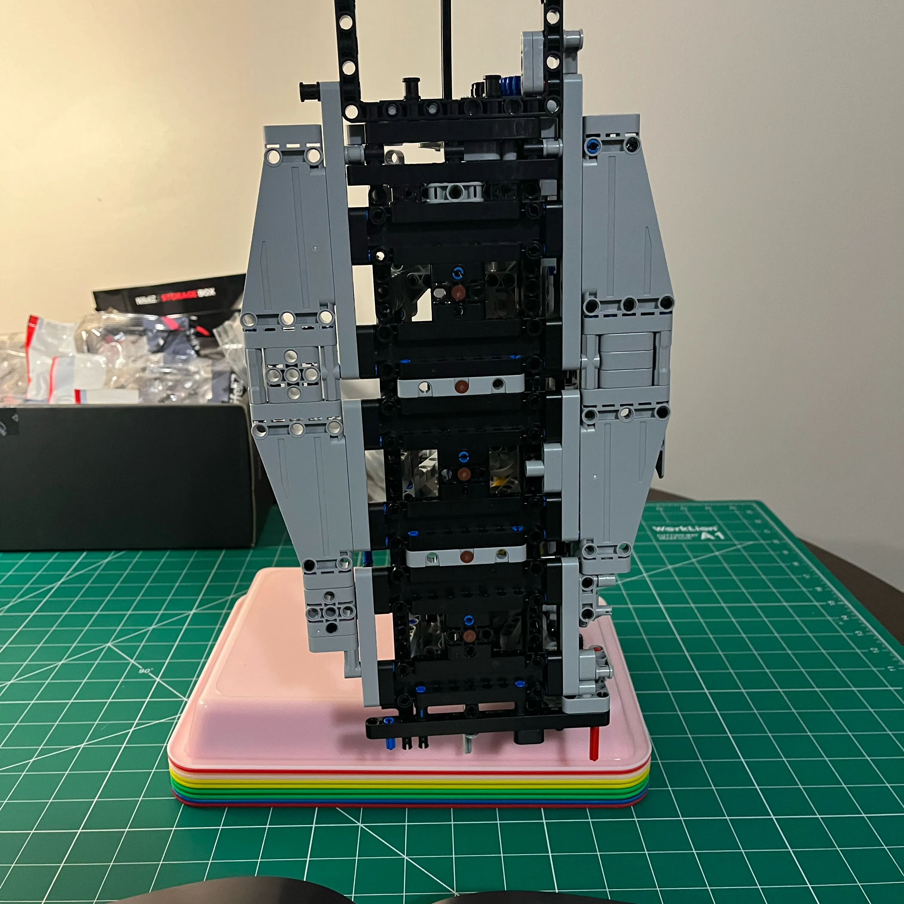
Here’s the crank assembled without pistons attached
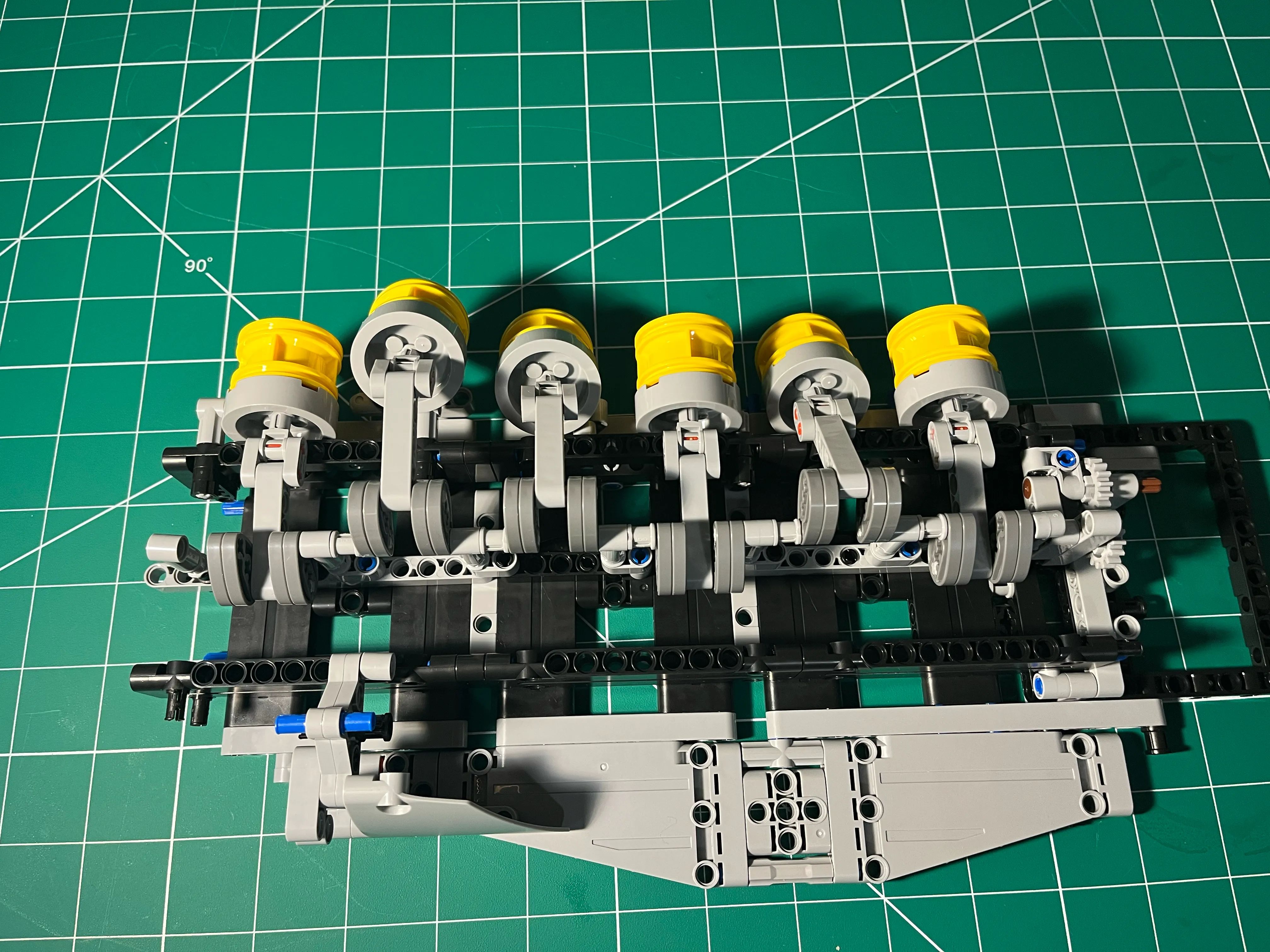
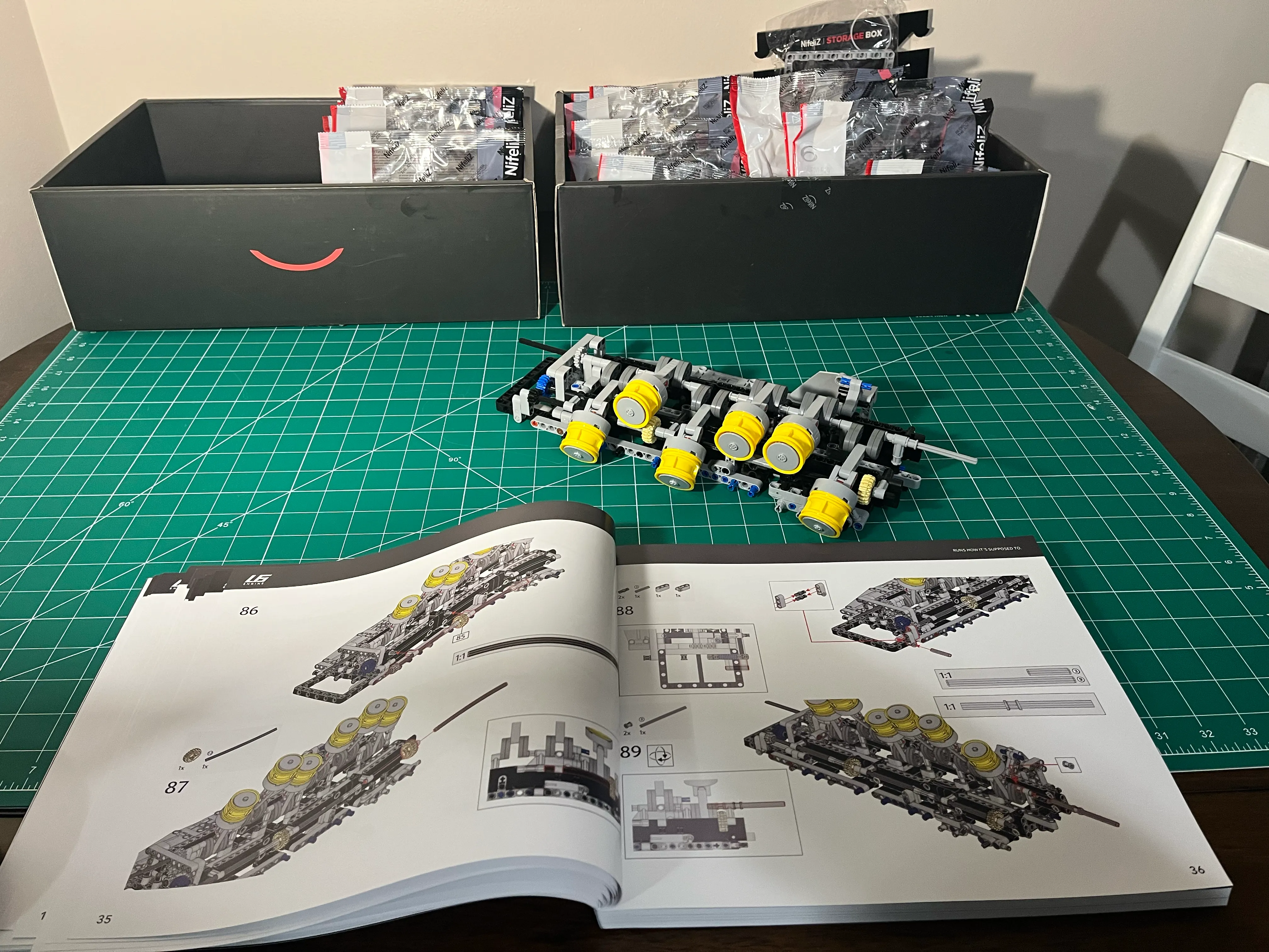
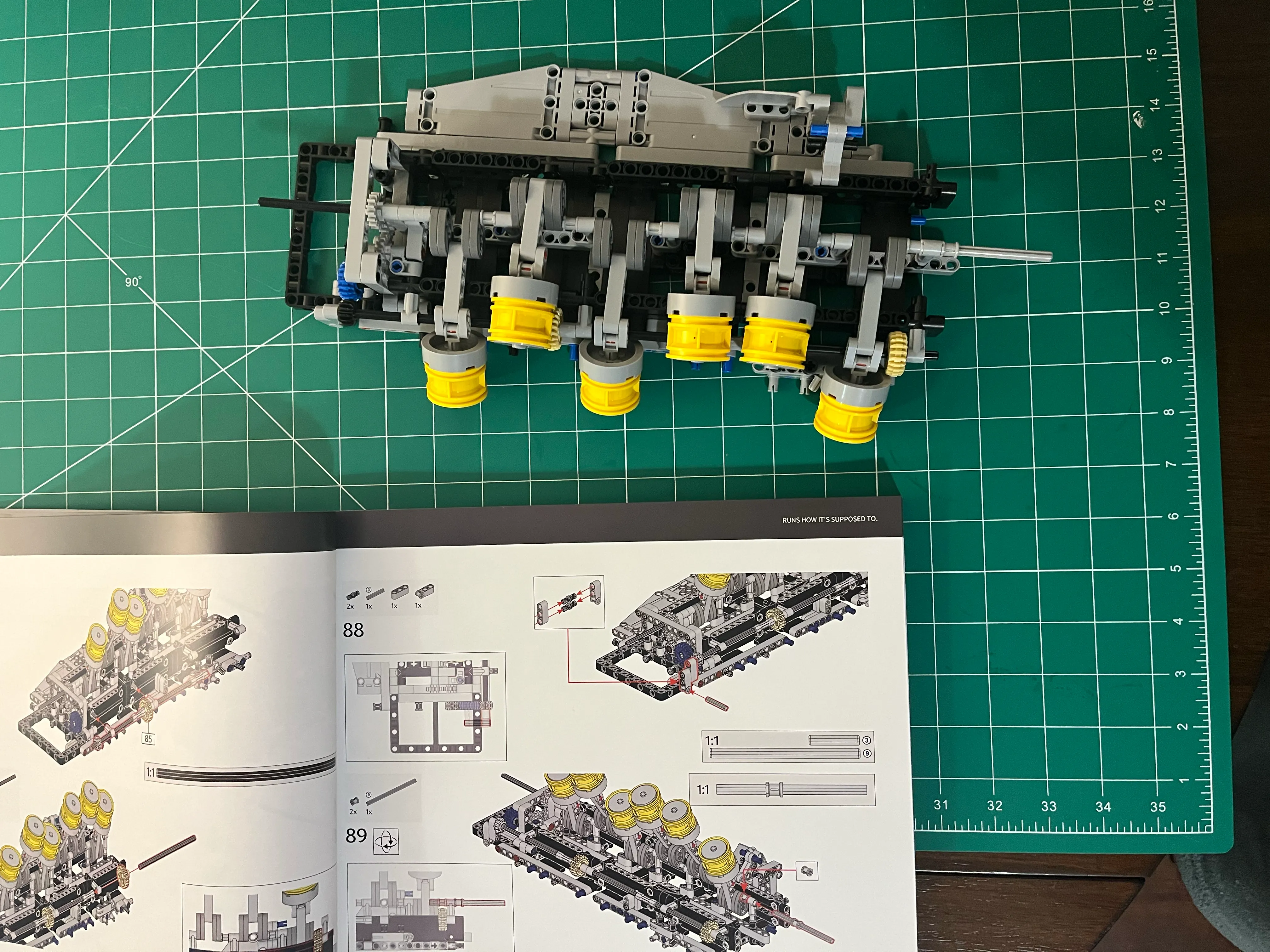
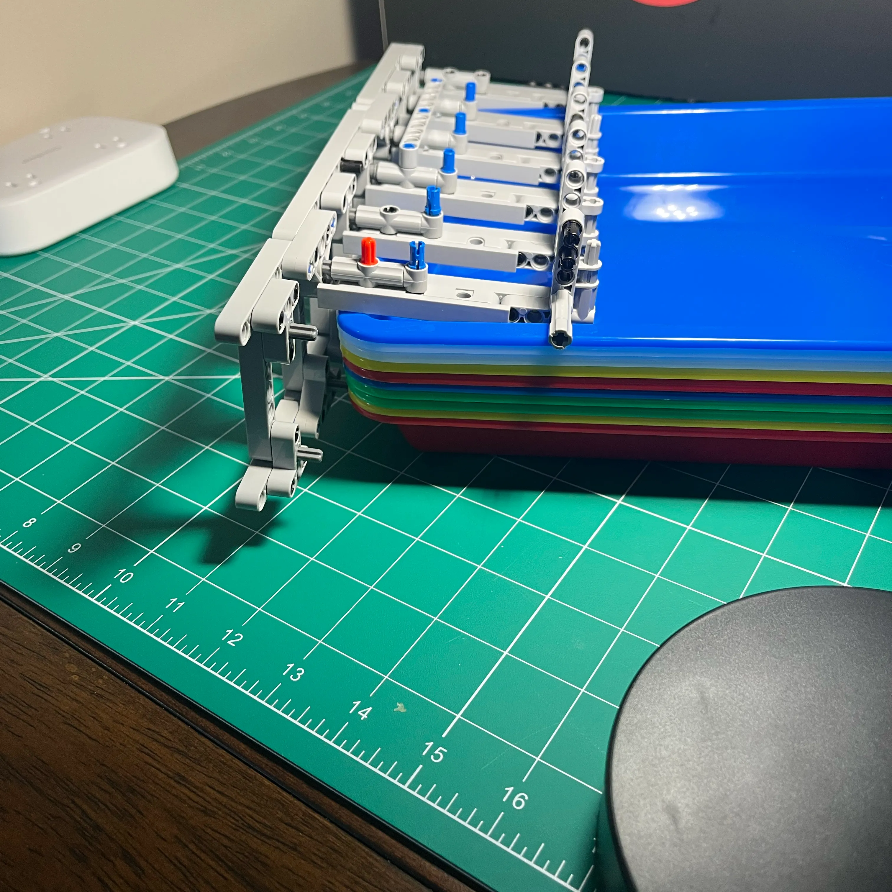
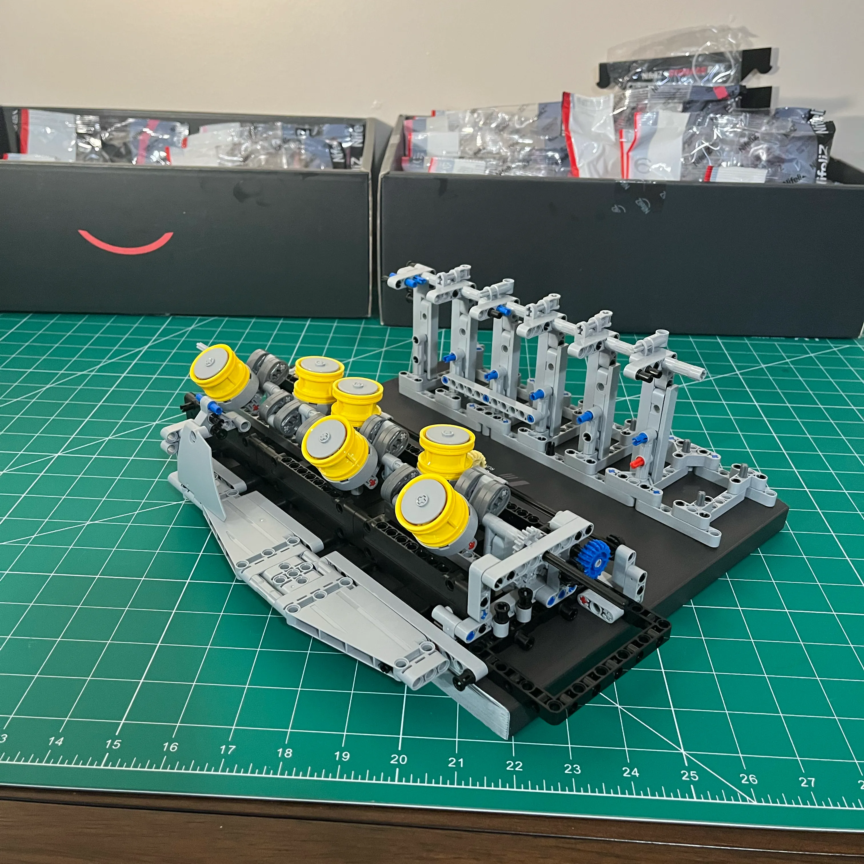
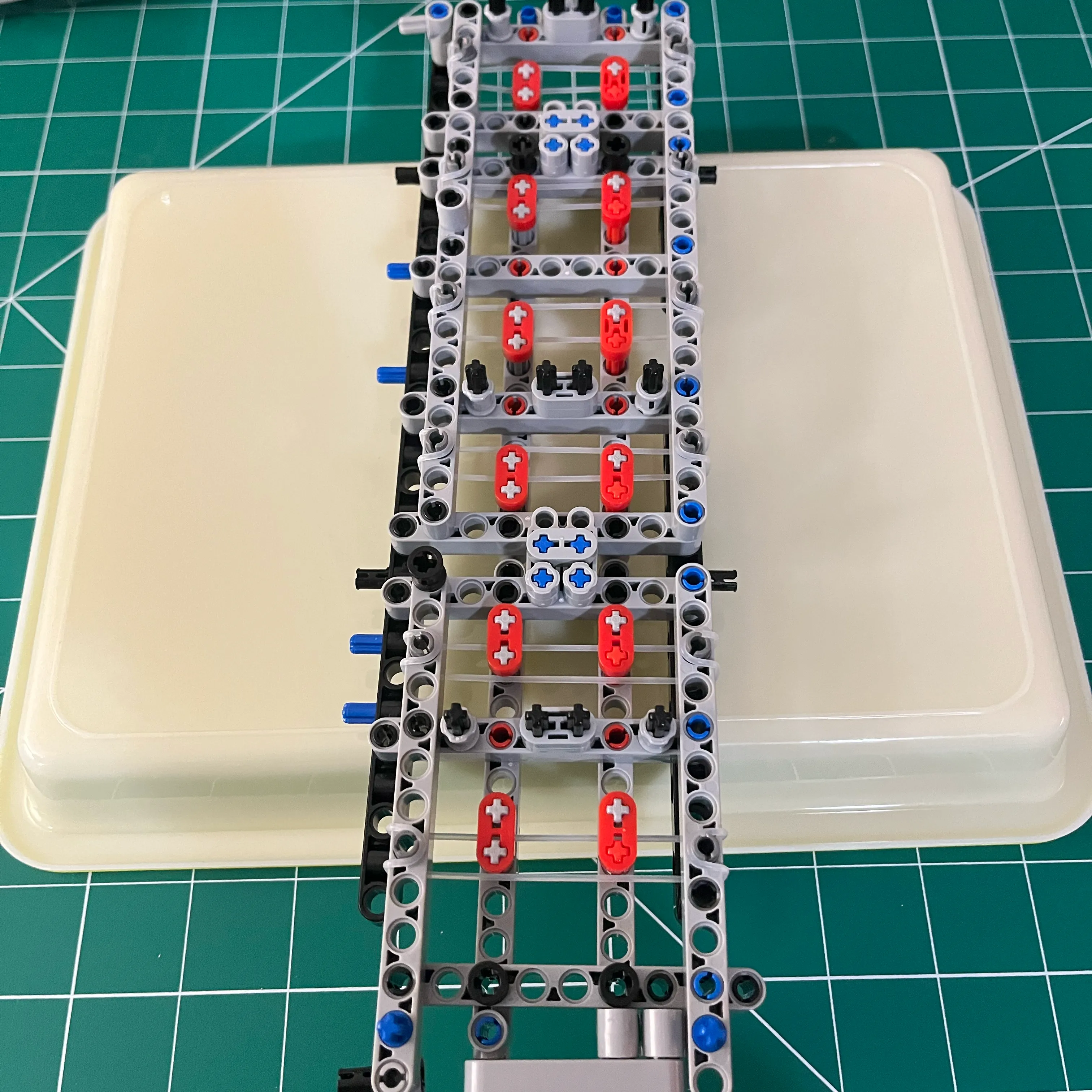
Here’s the crank and pistons assembled and installed in the frame. I turned the frame upside down to see how the pistons might look in their bores once the engine block is installed.
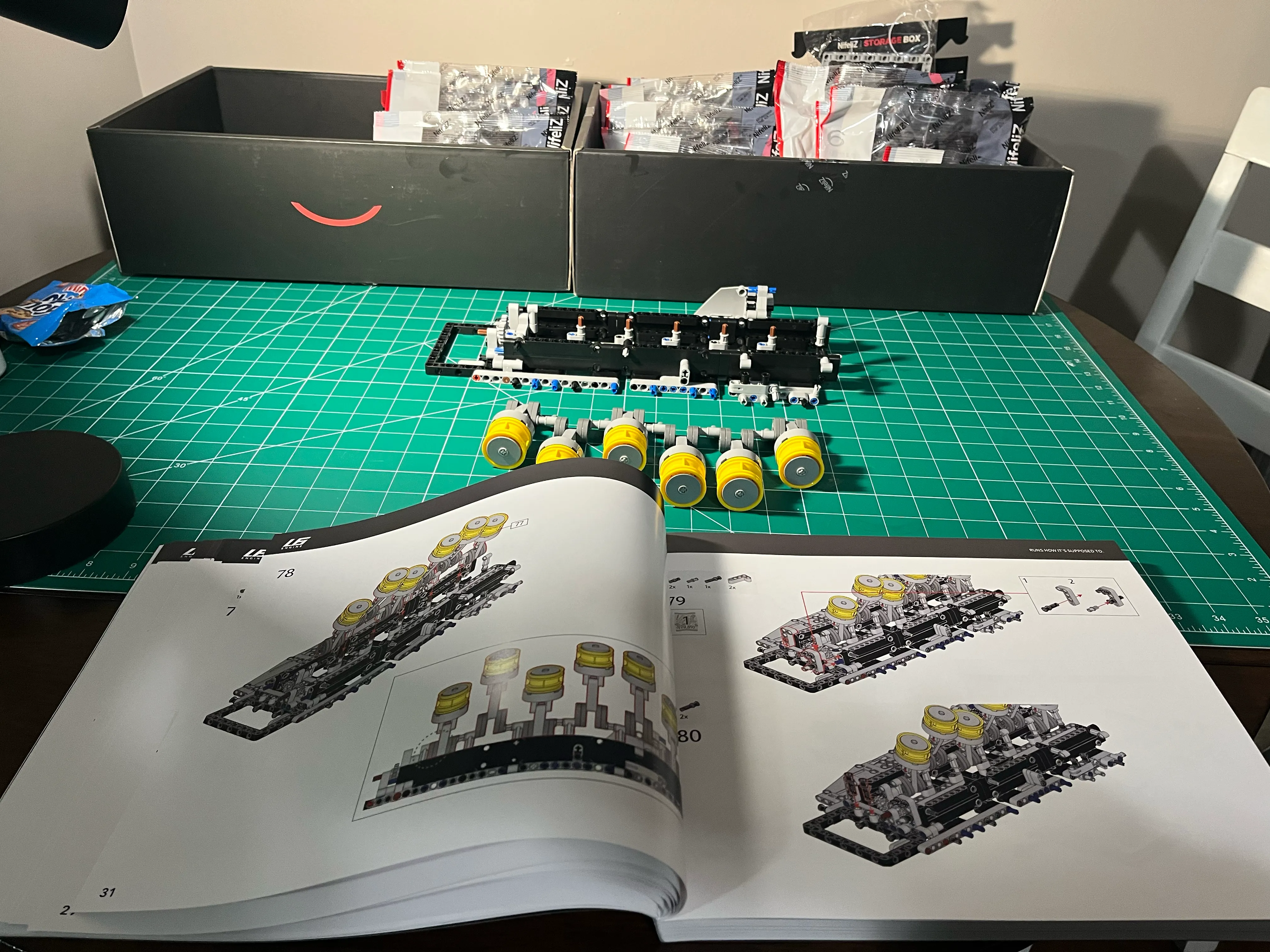
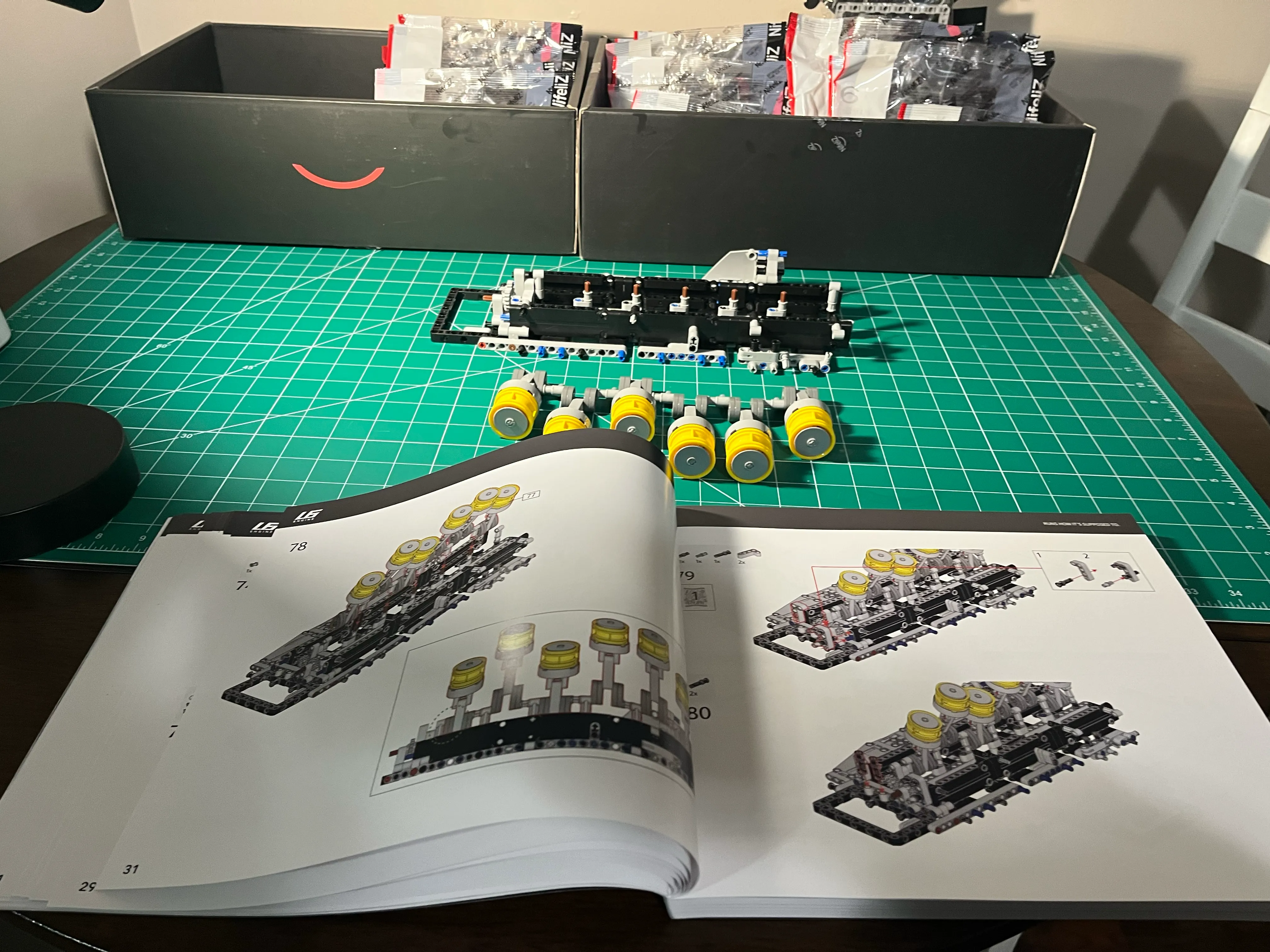
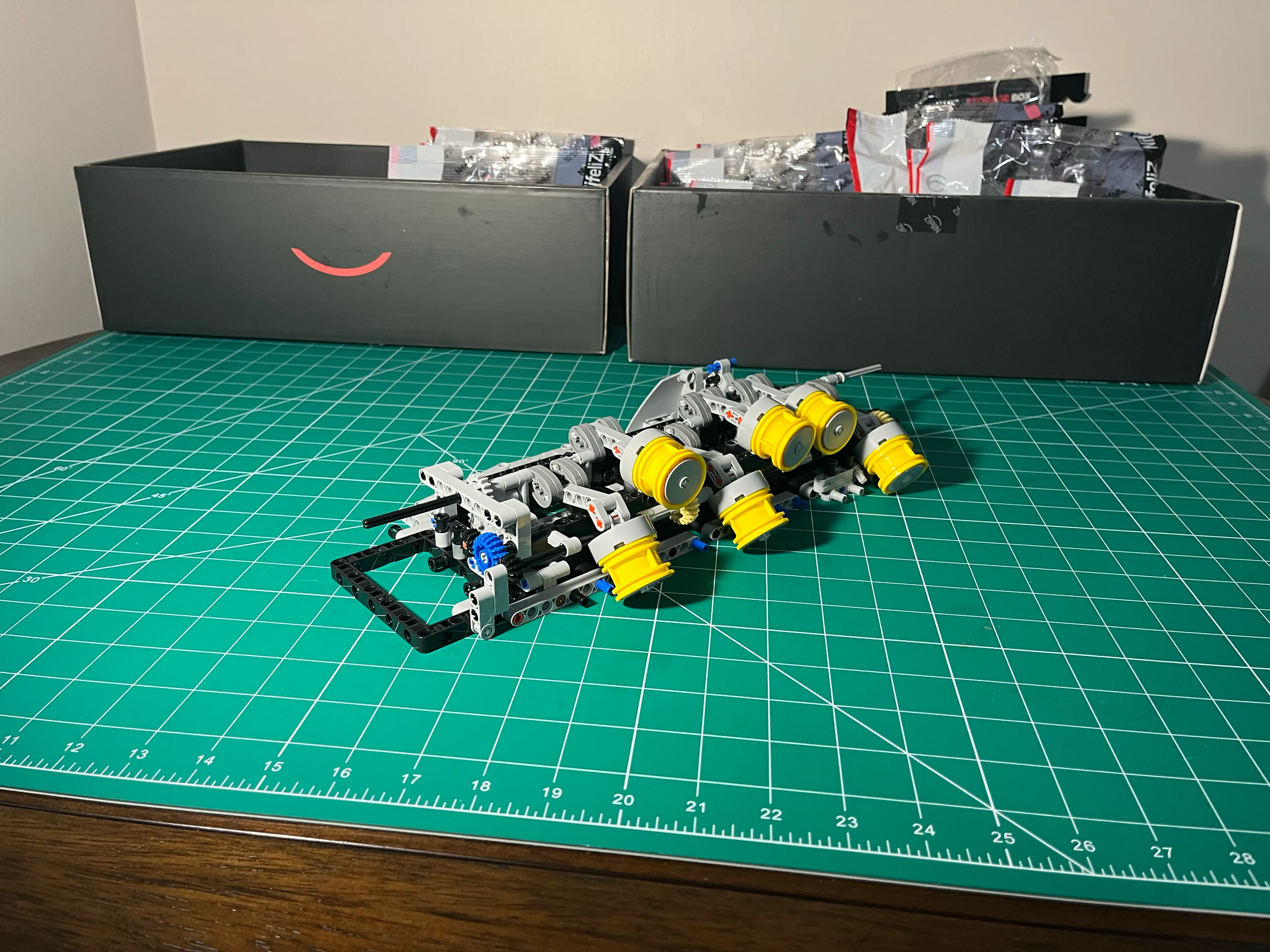
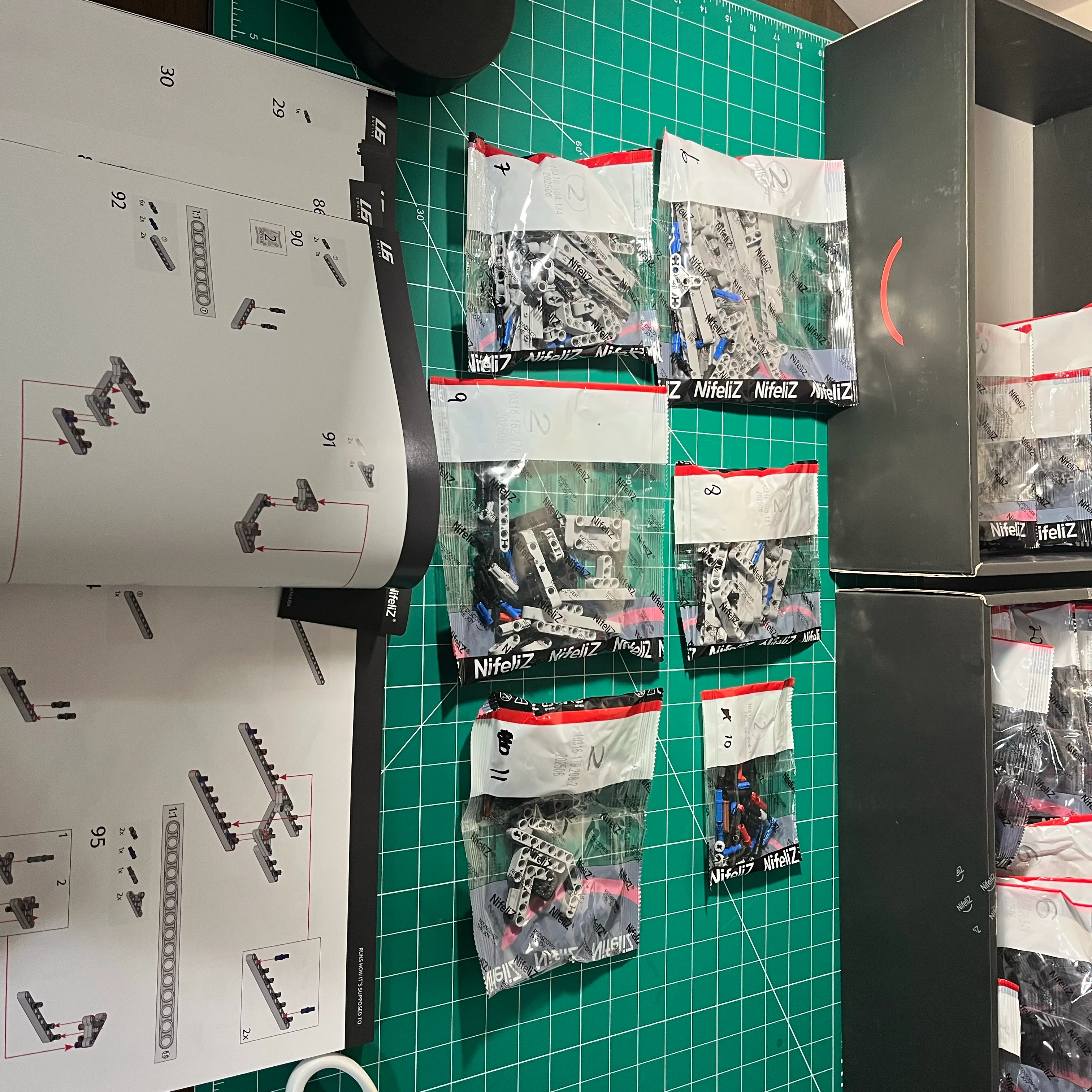
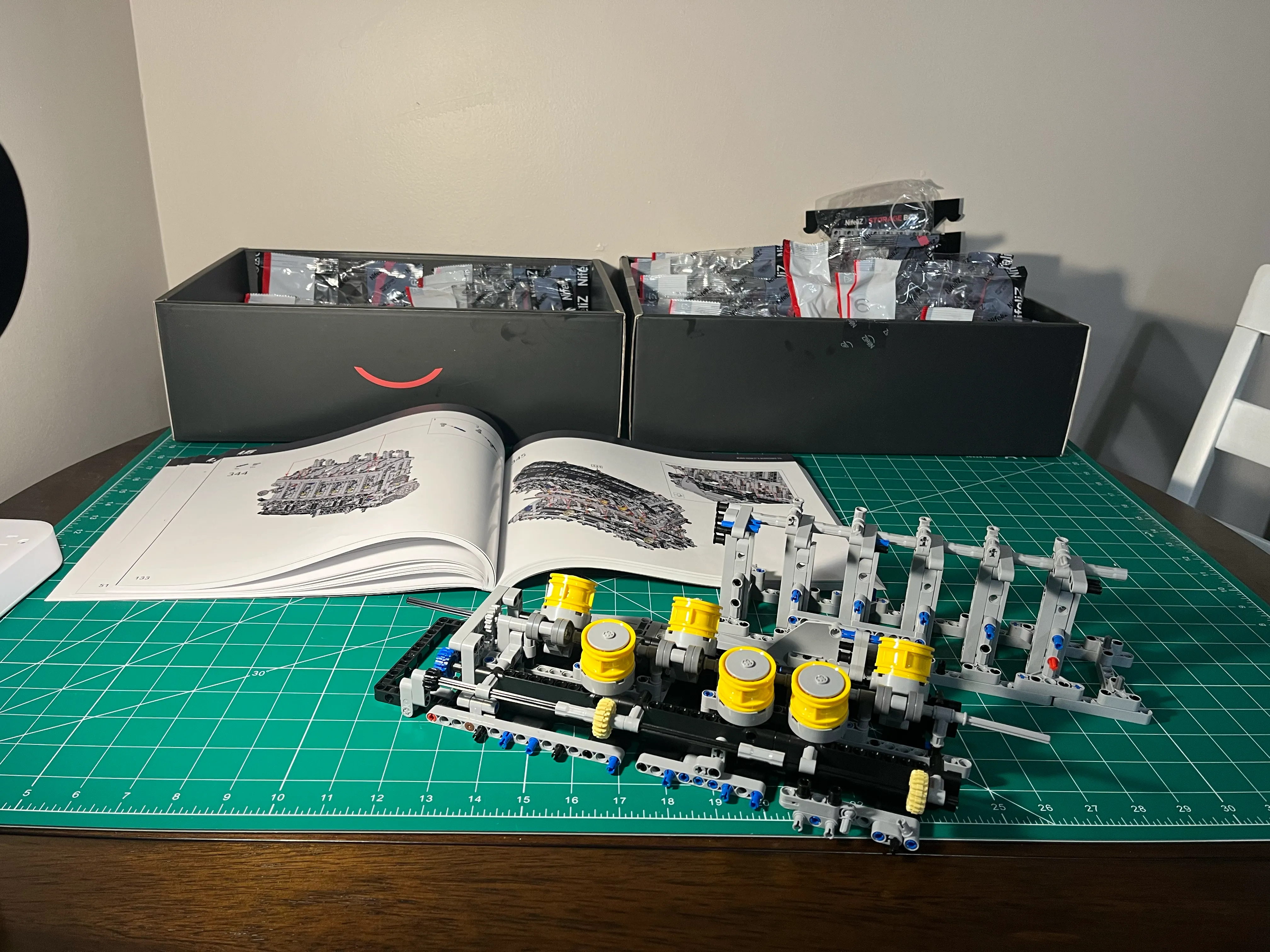
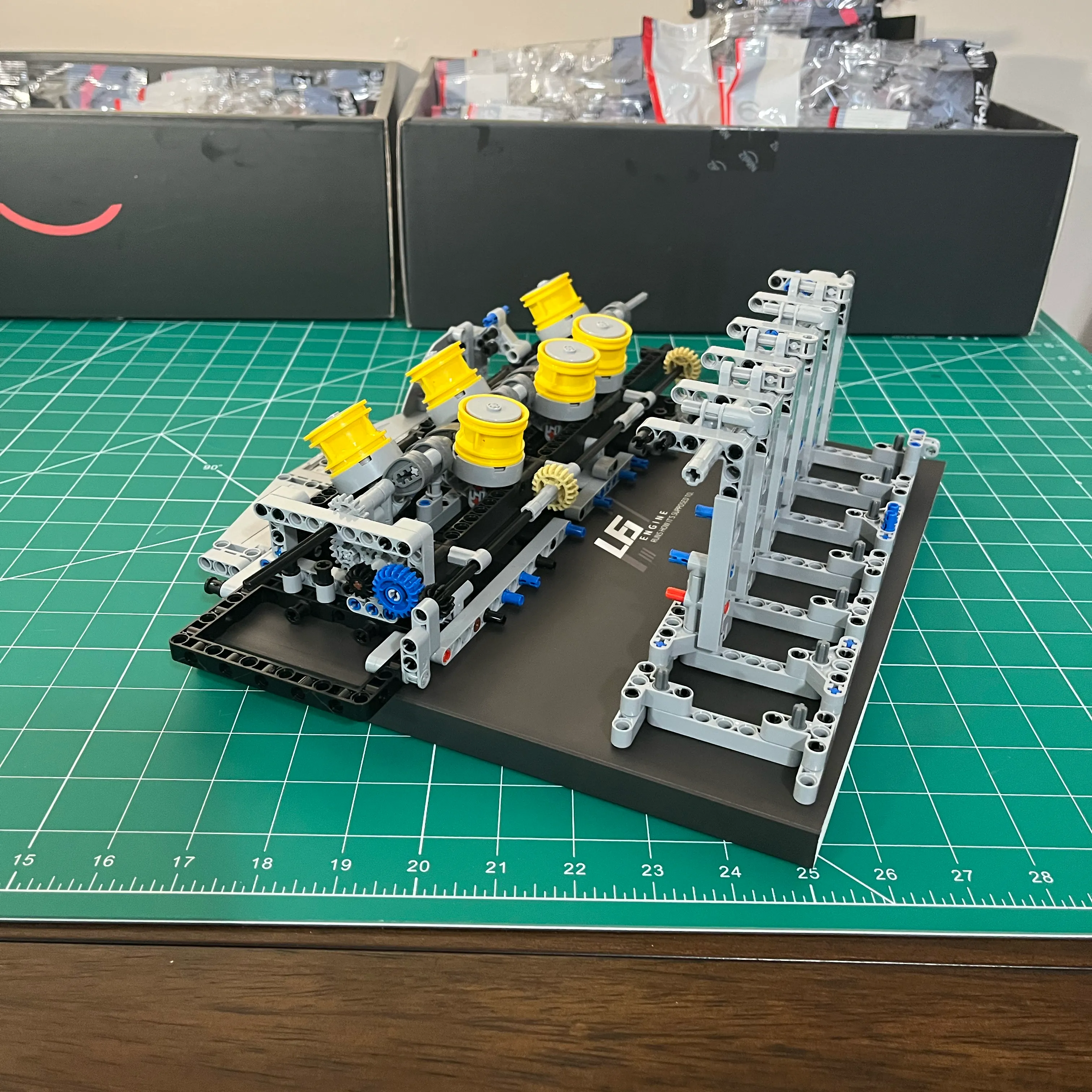
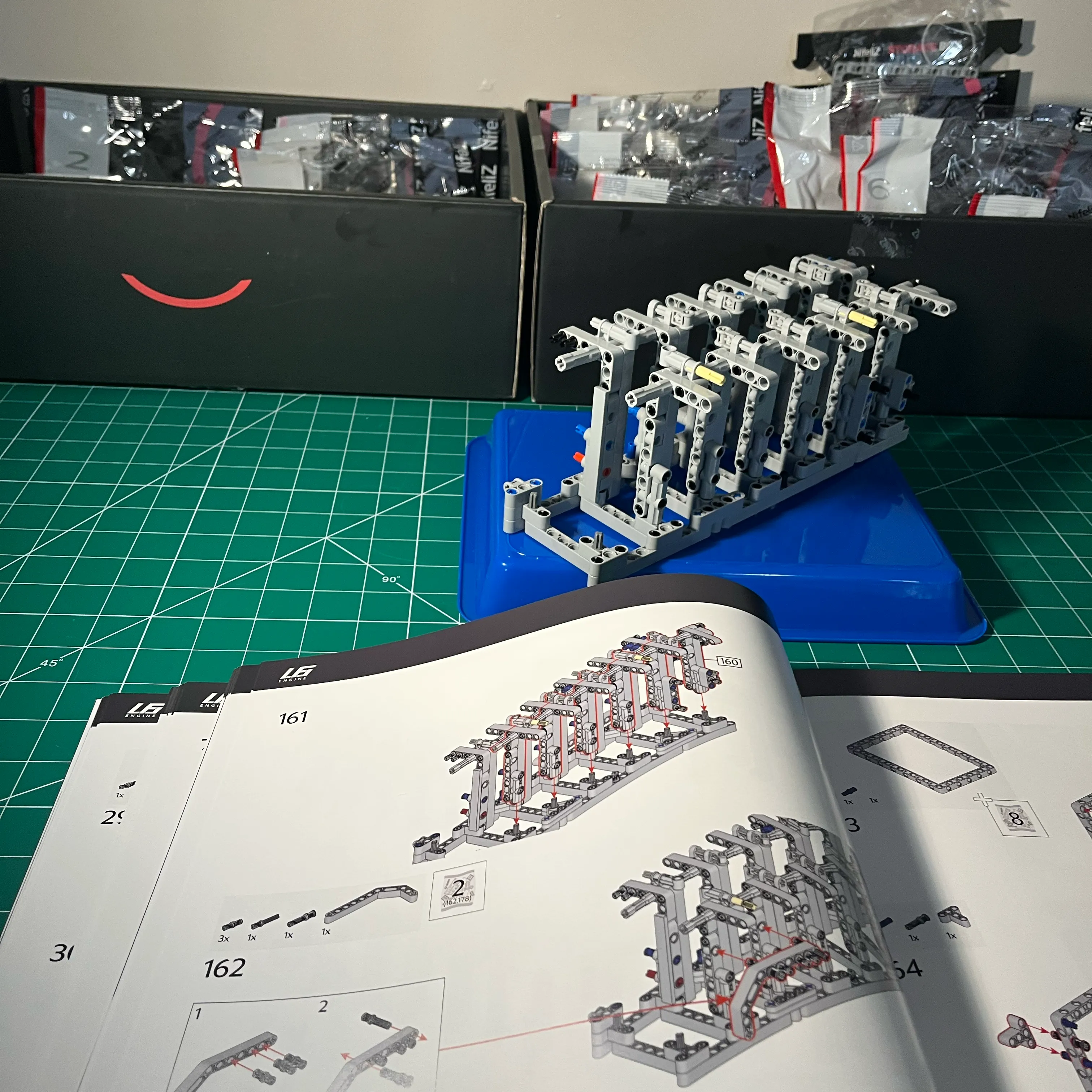
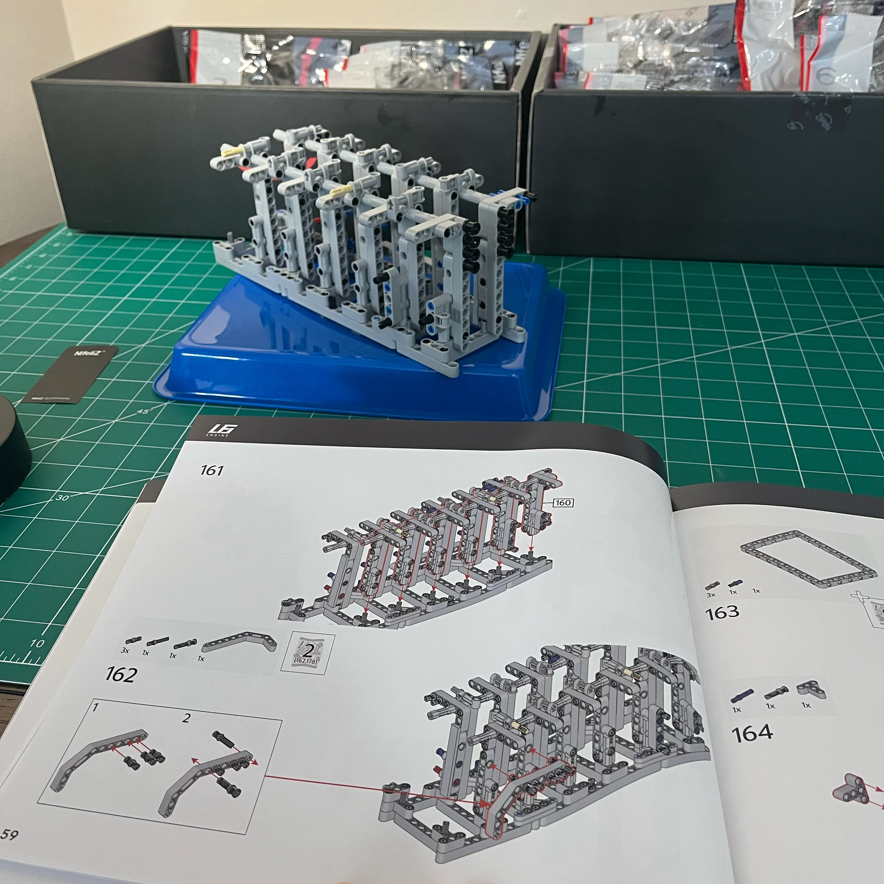
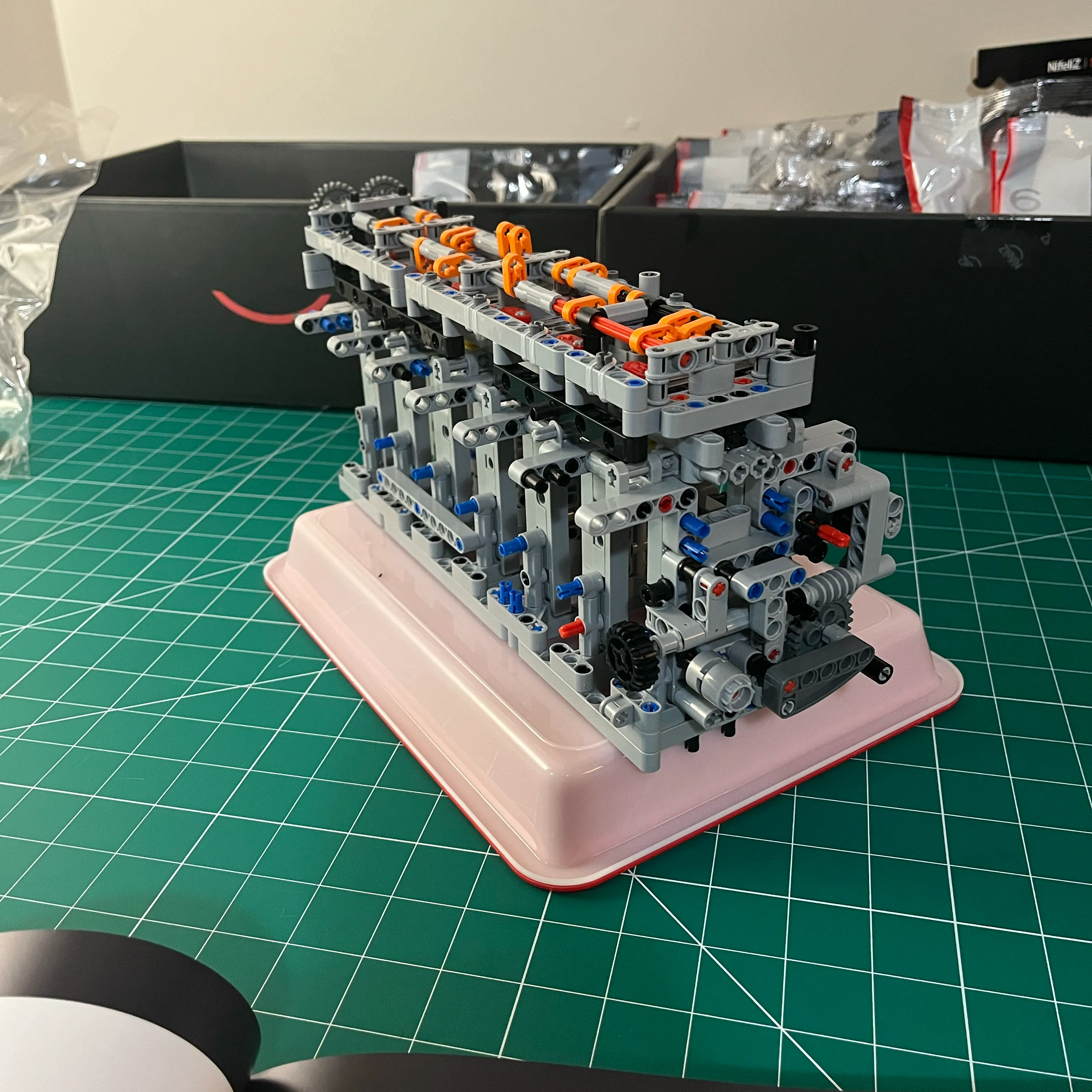
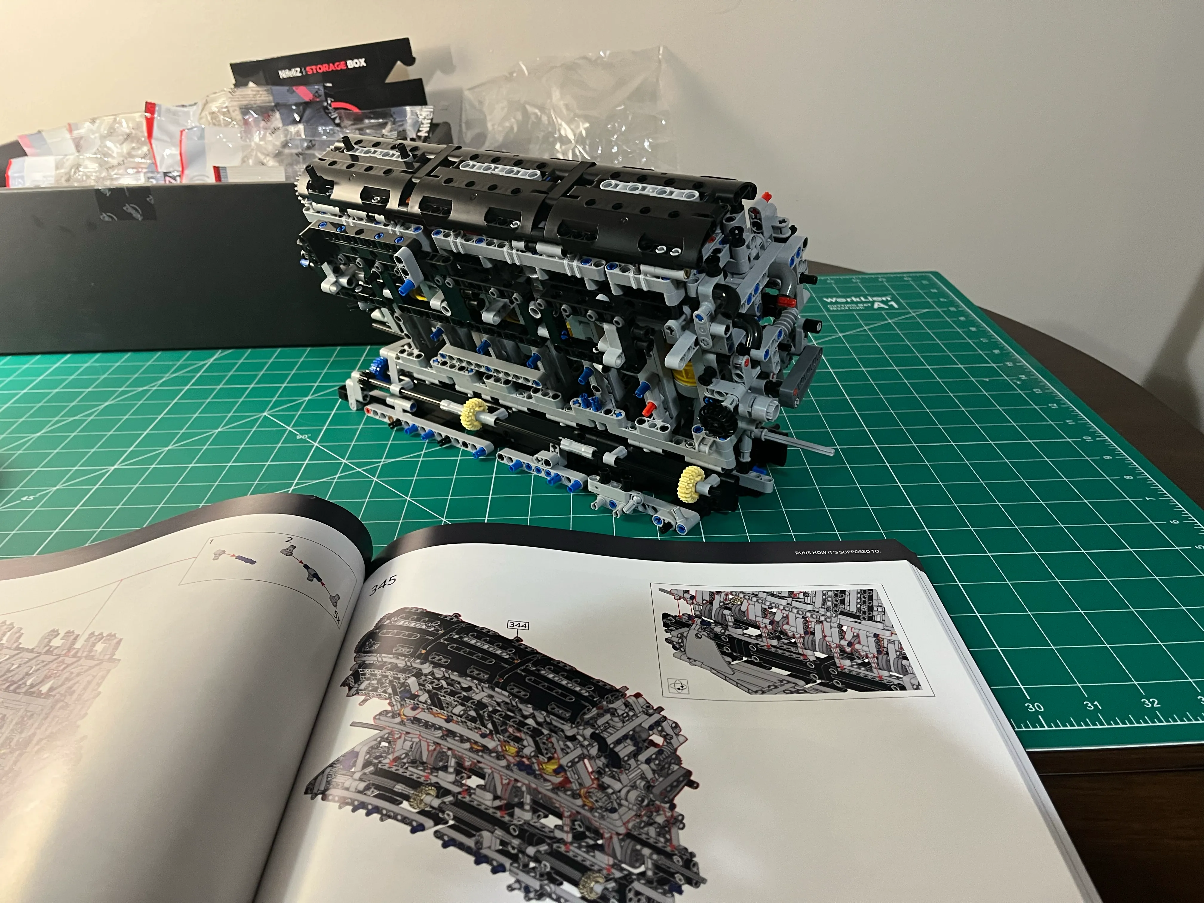
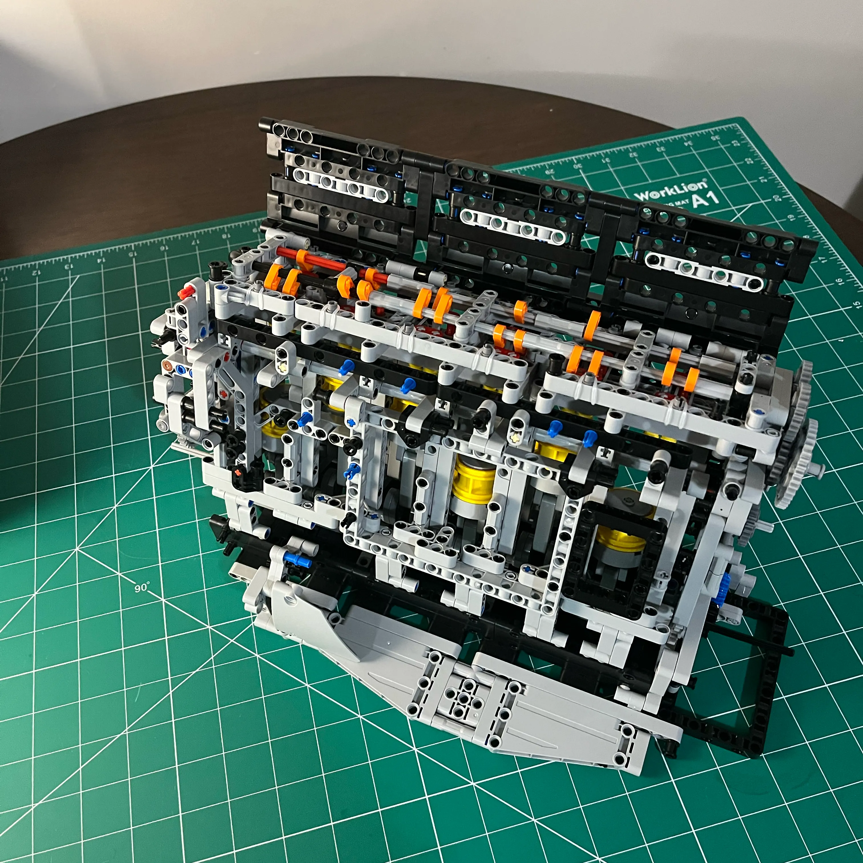
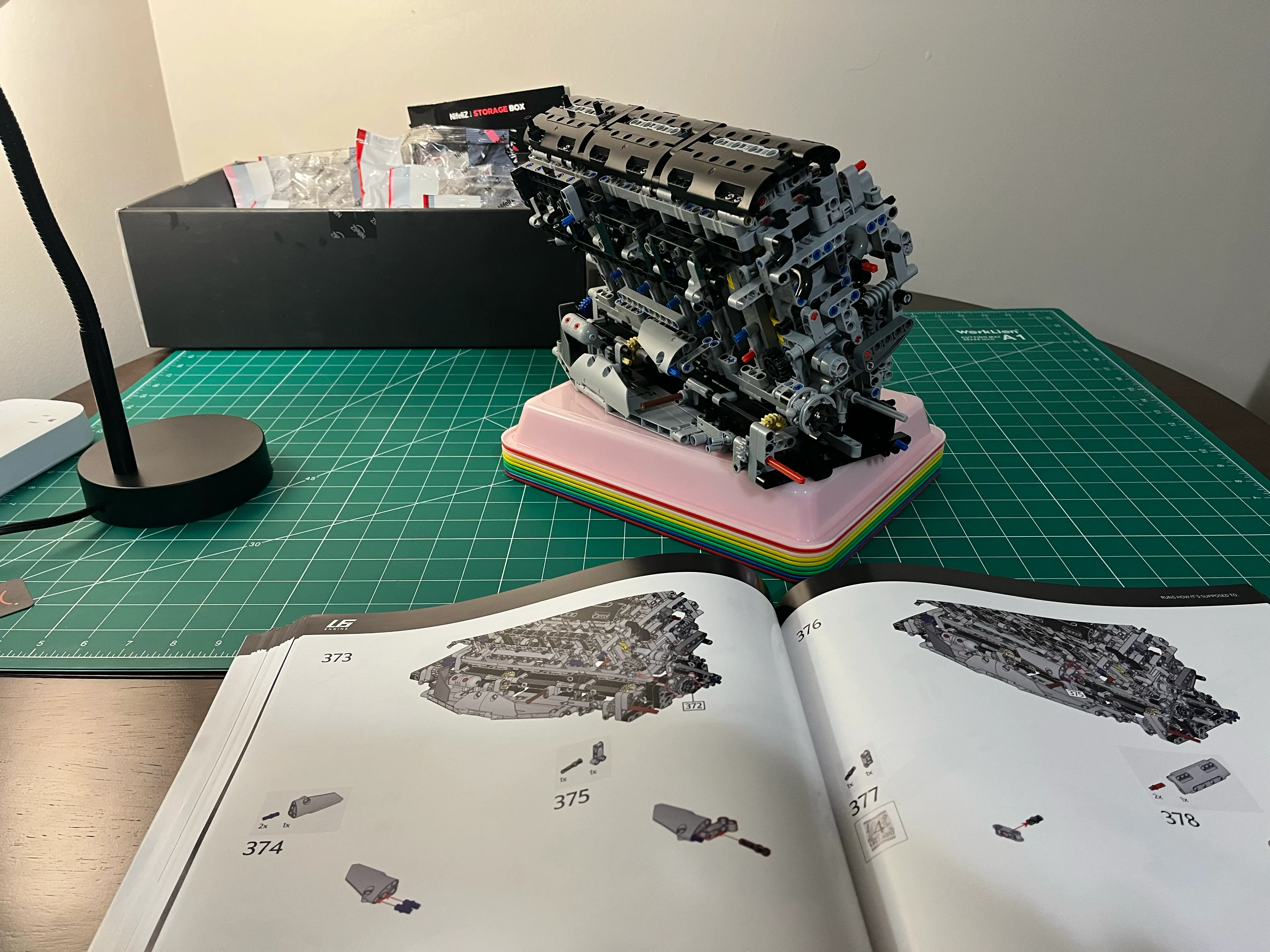
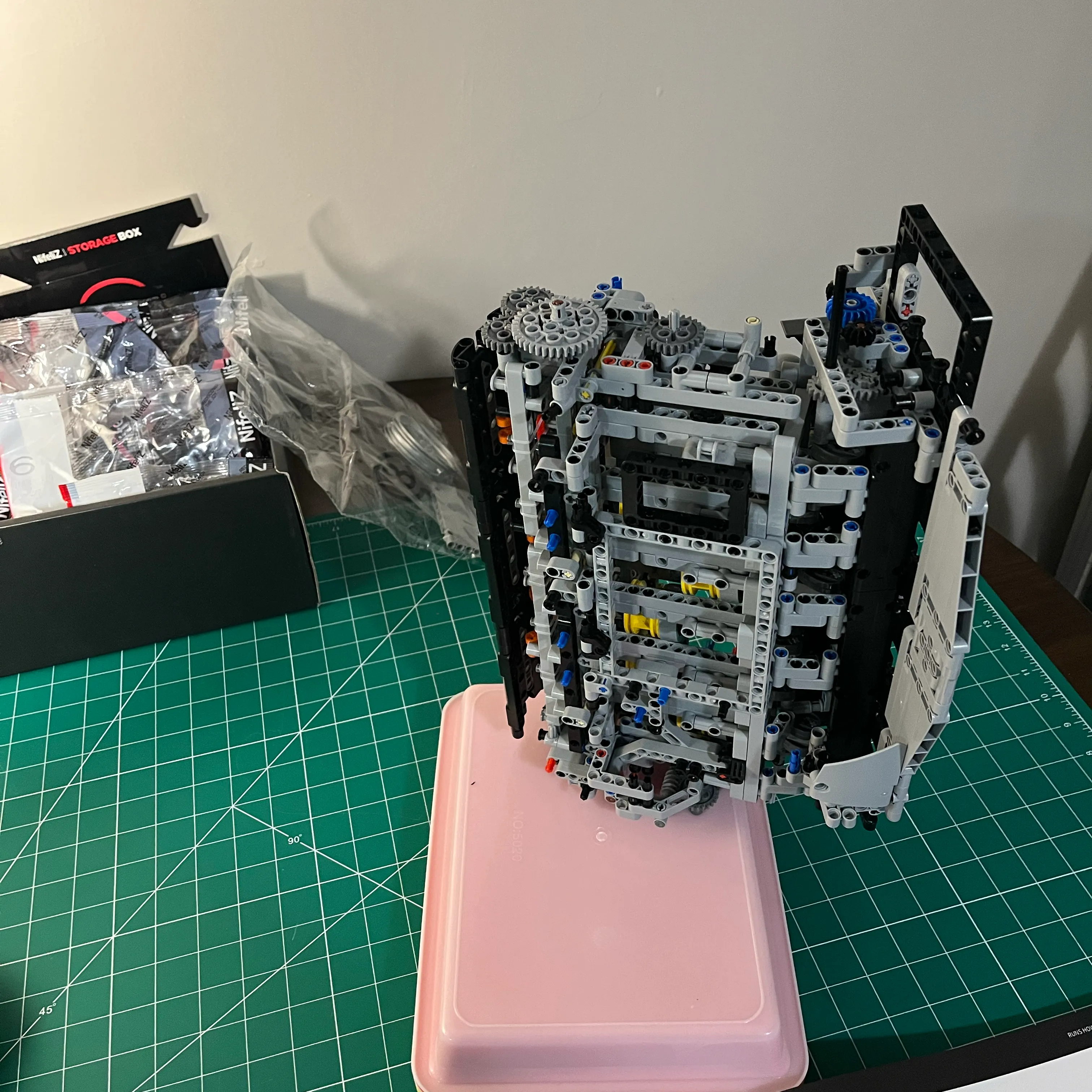
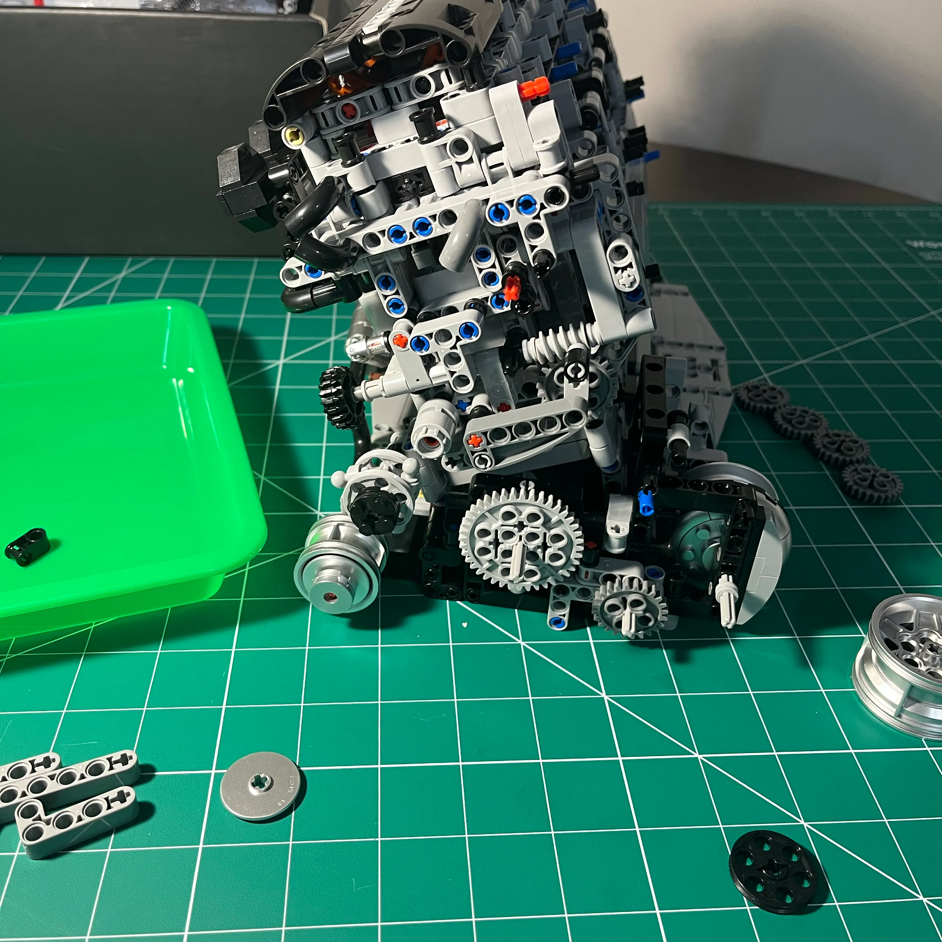
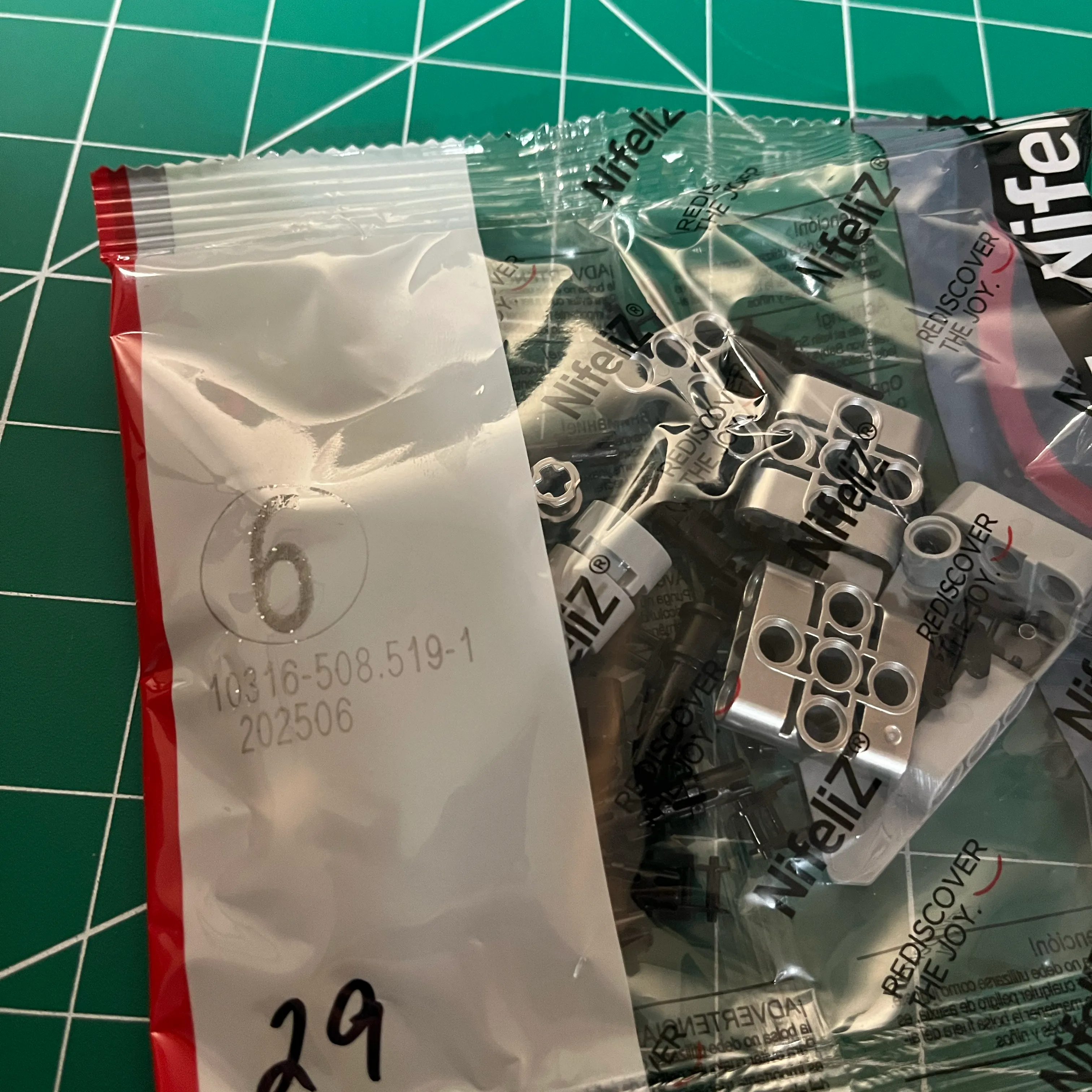
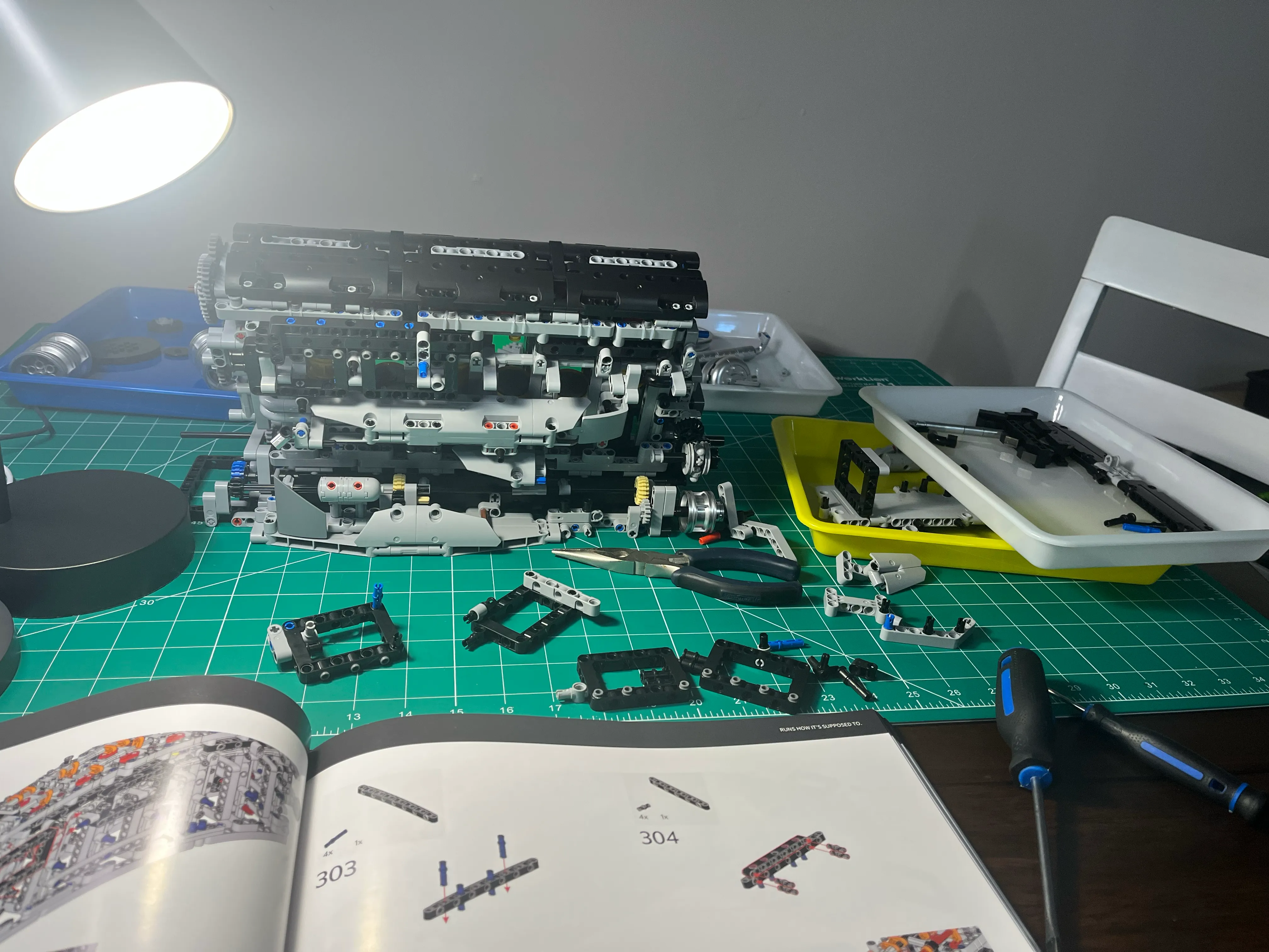
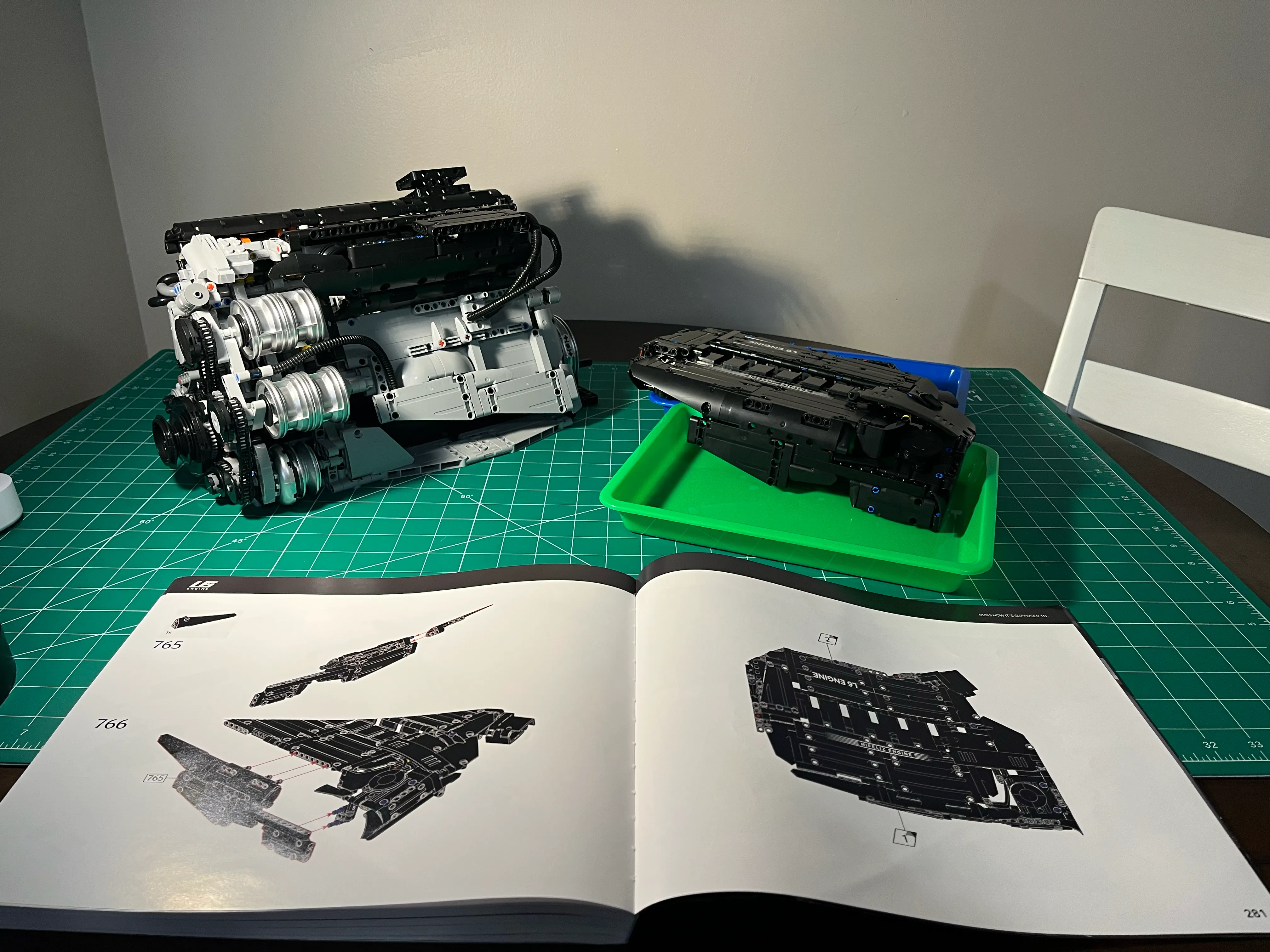
Before I realized the binding issues, I was on bag 29 out of 40. Here’s a picture of the engine before I realized there were problems.
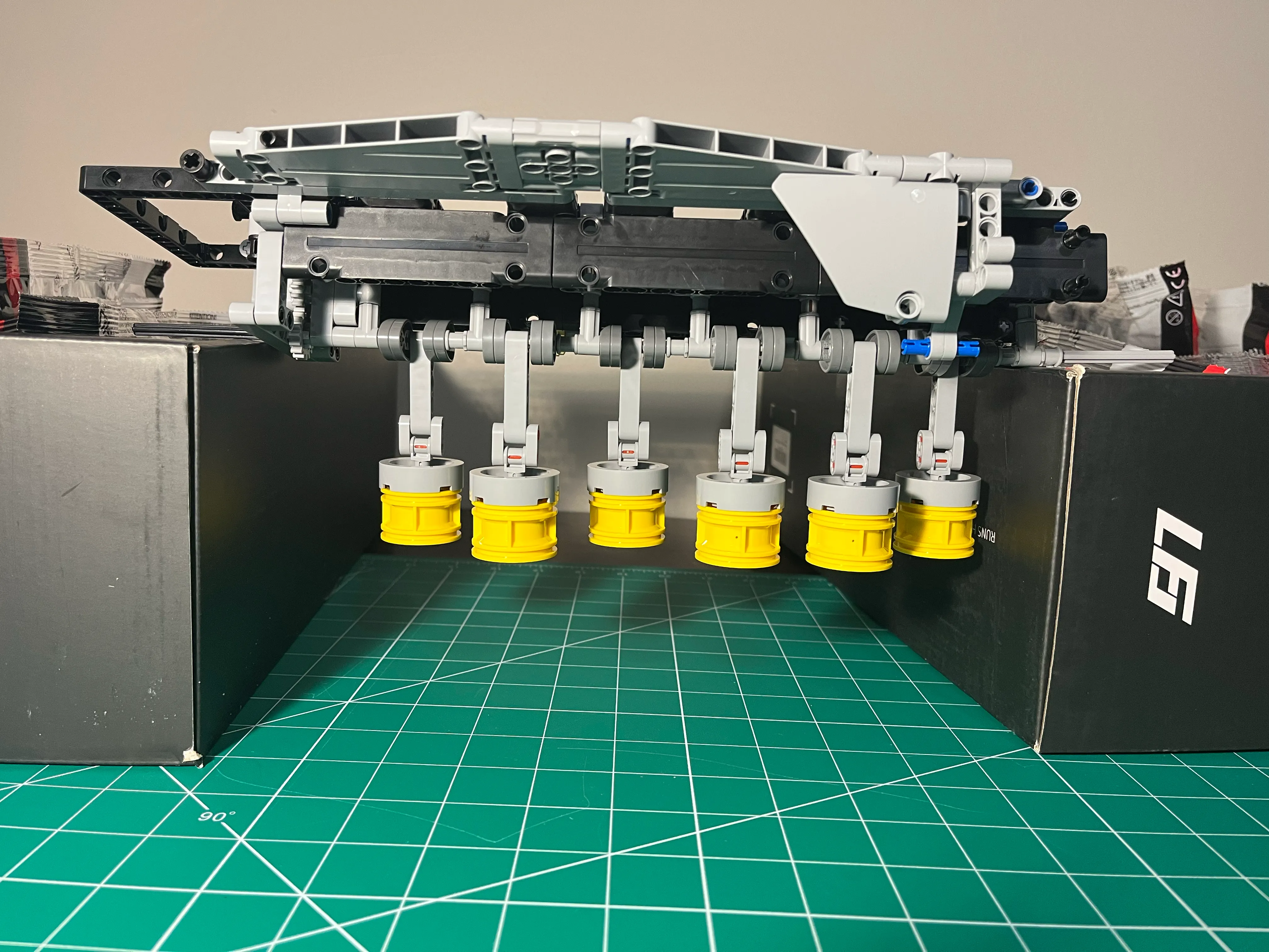
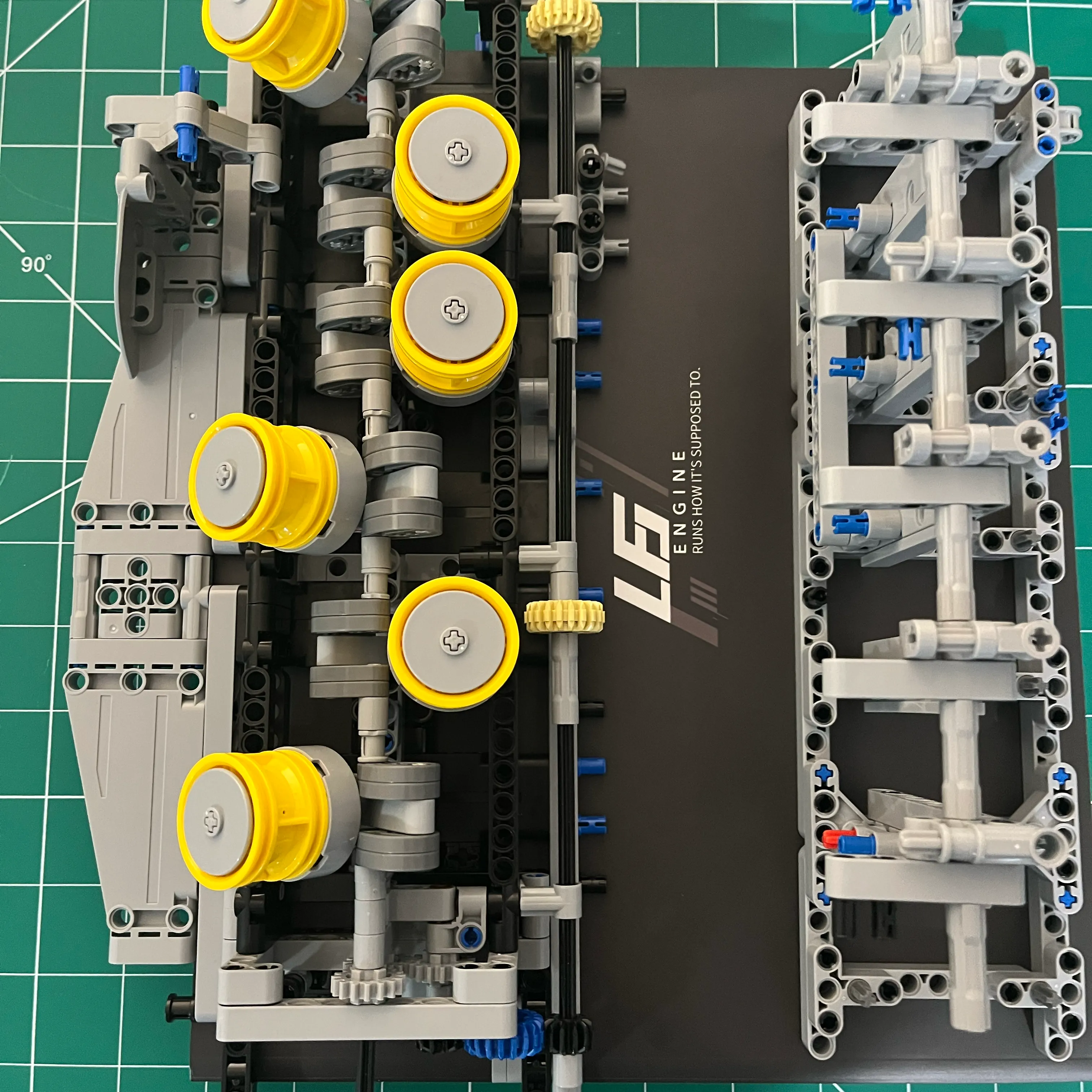
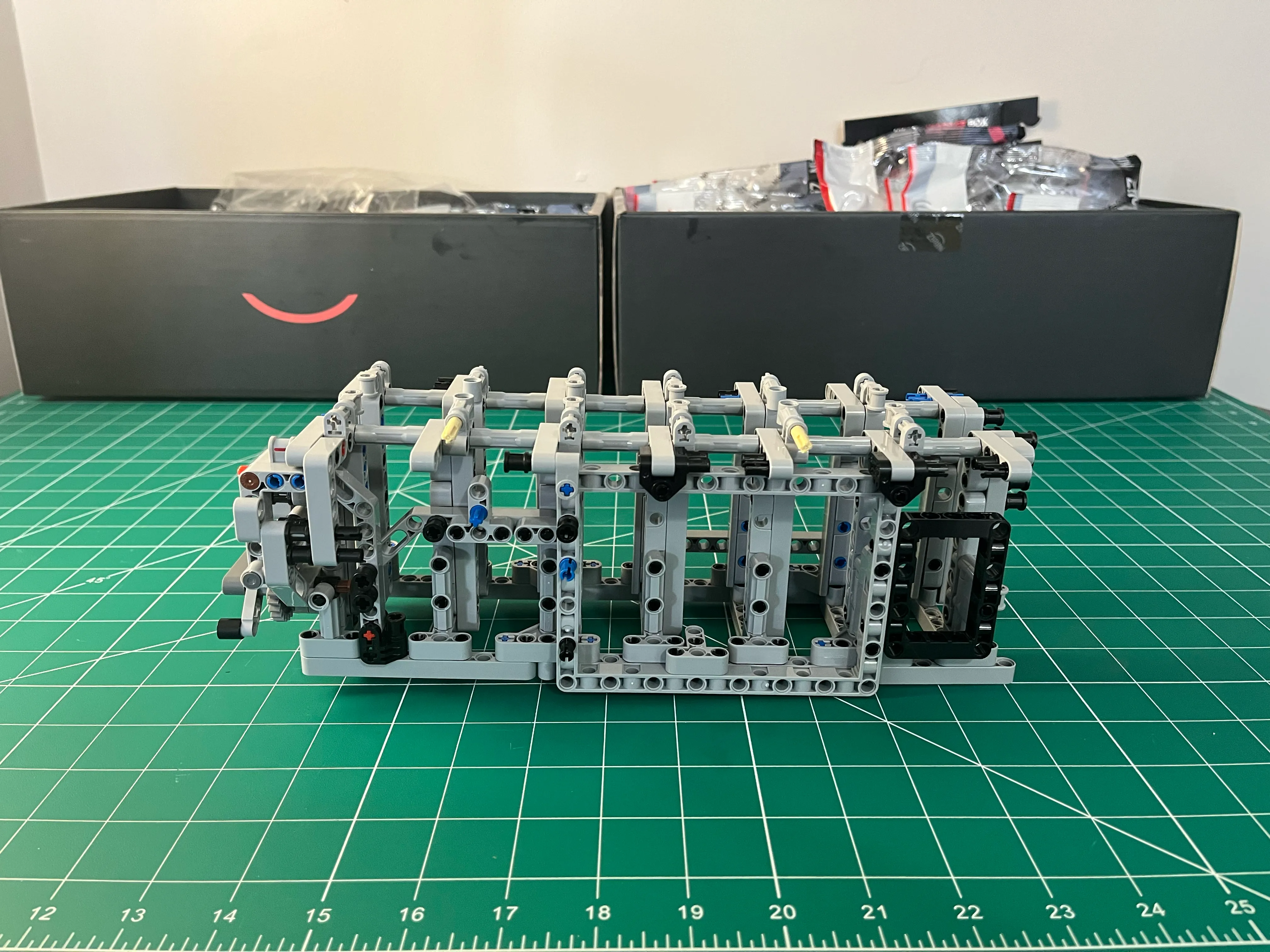
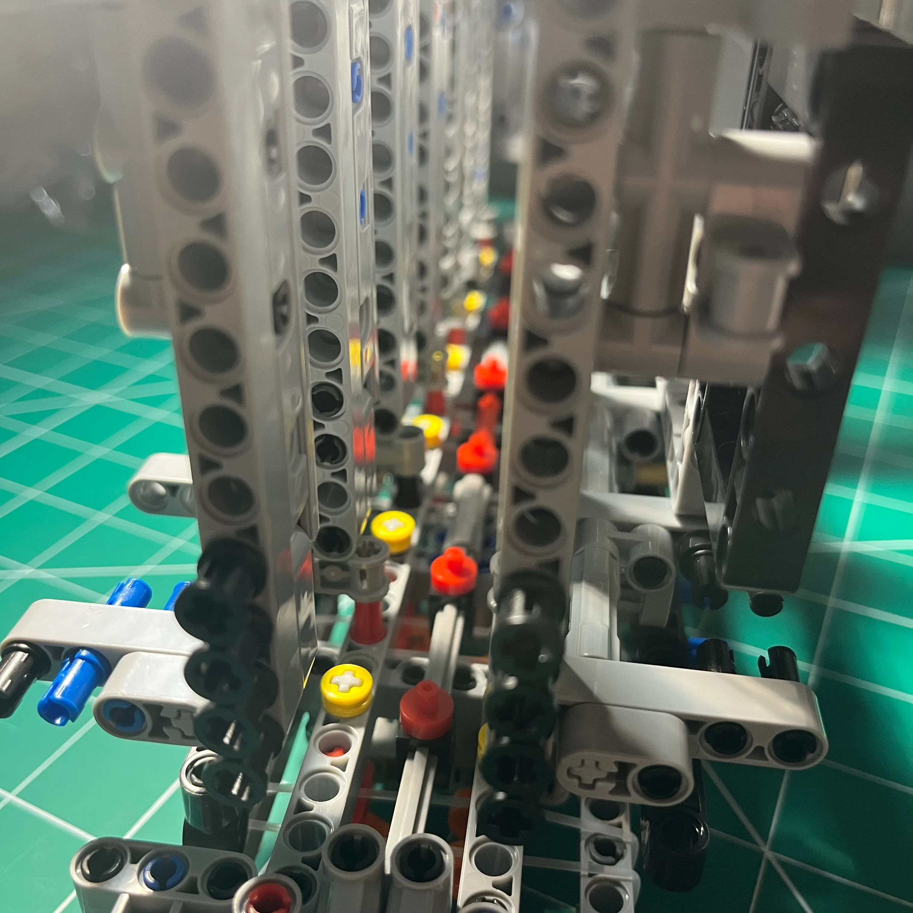
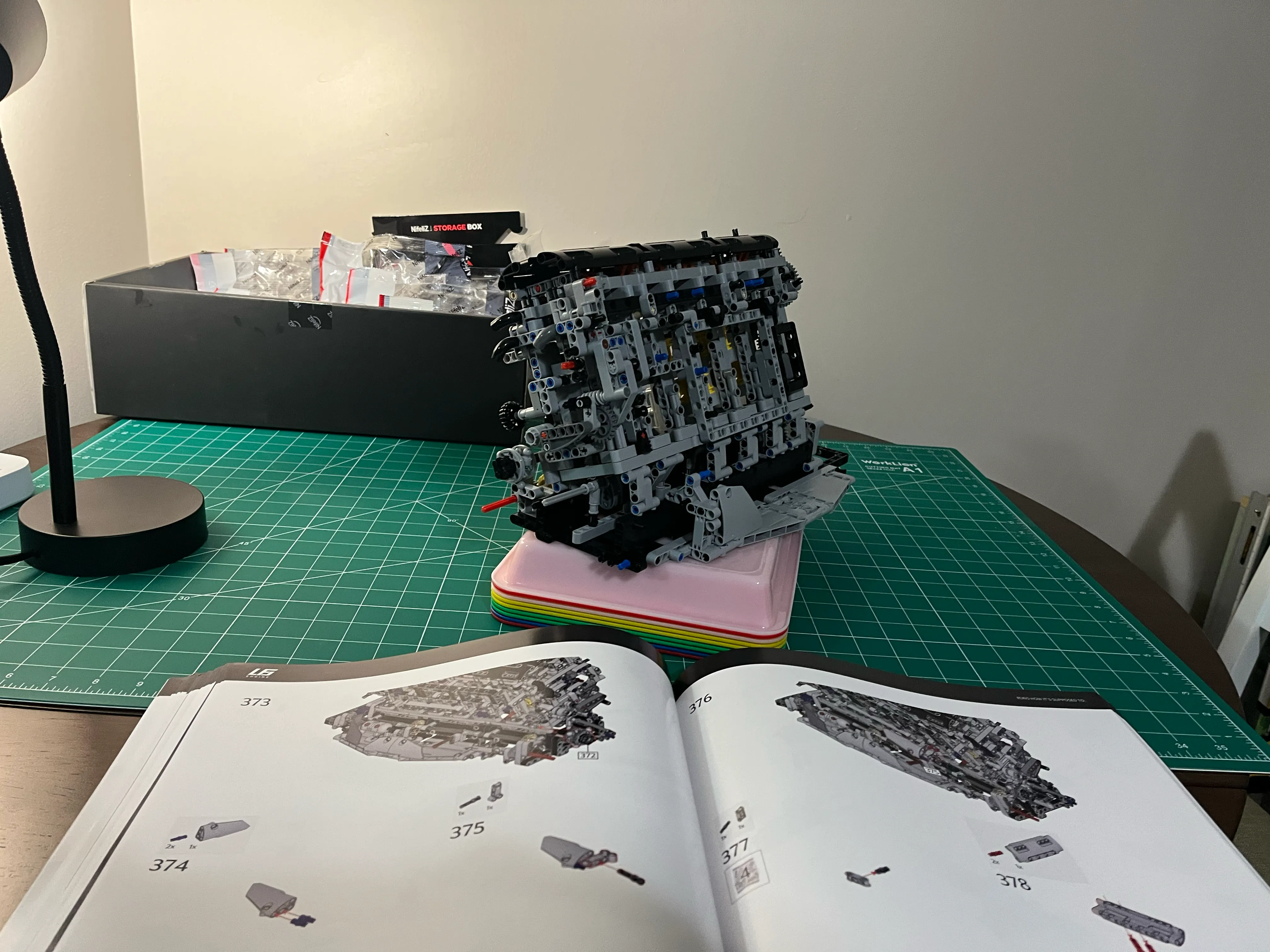
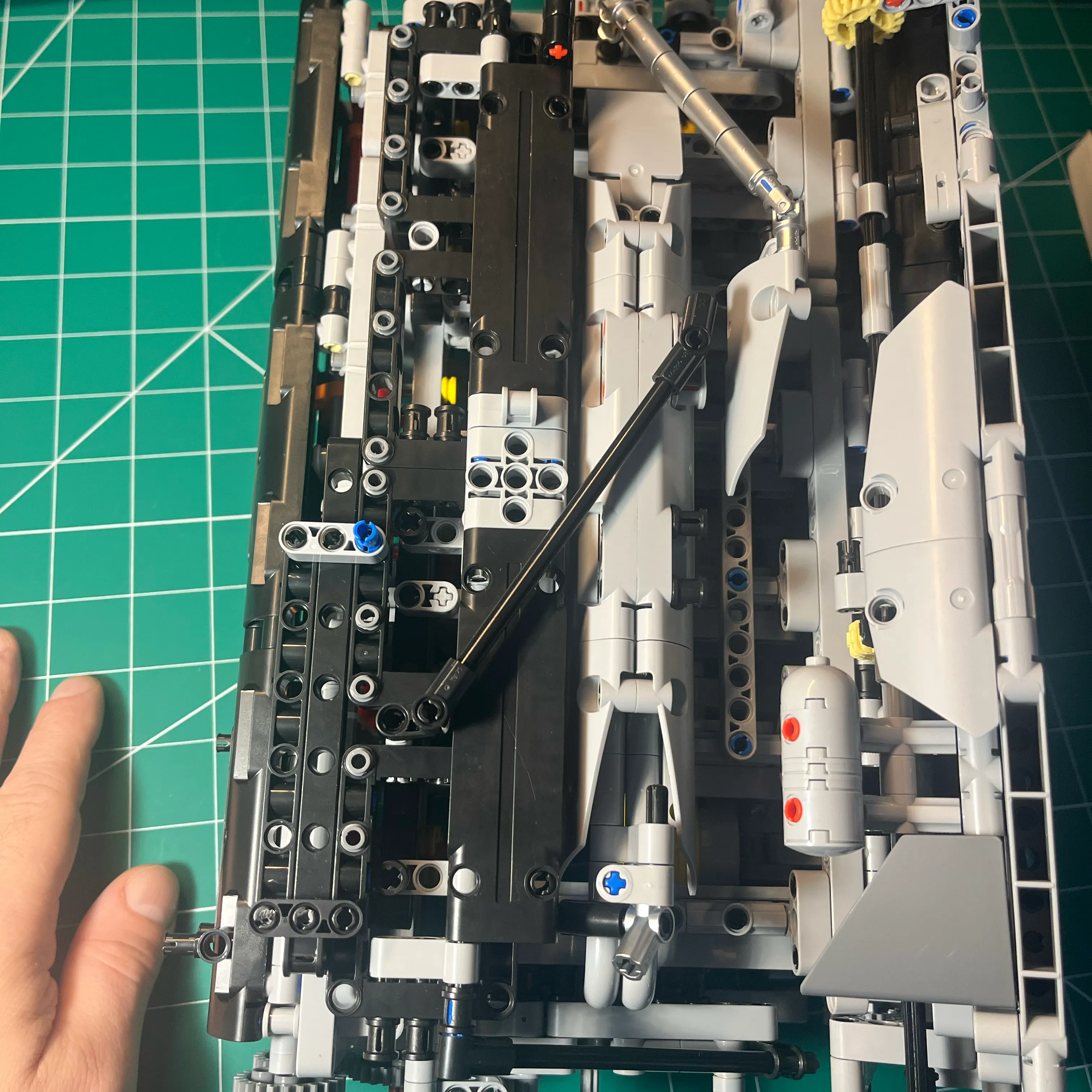
Here’s what I could see - not much at all. I had to tear down to find the problems.
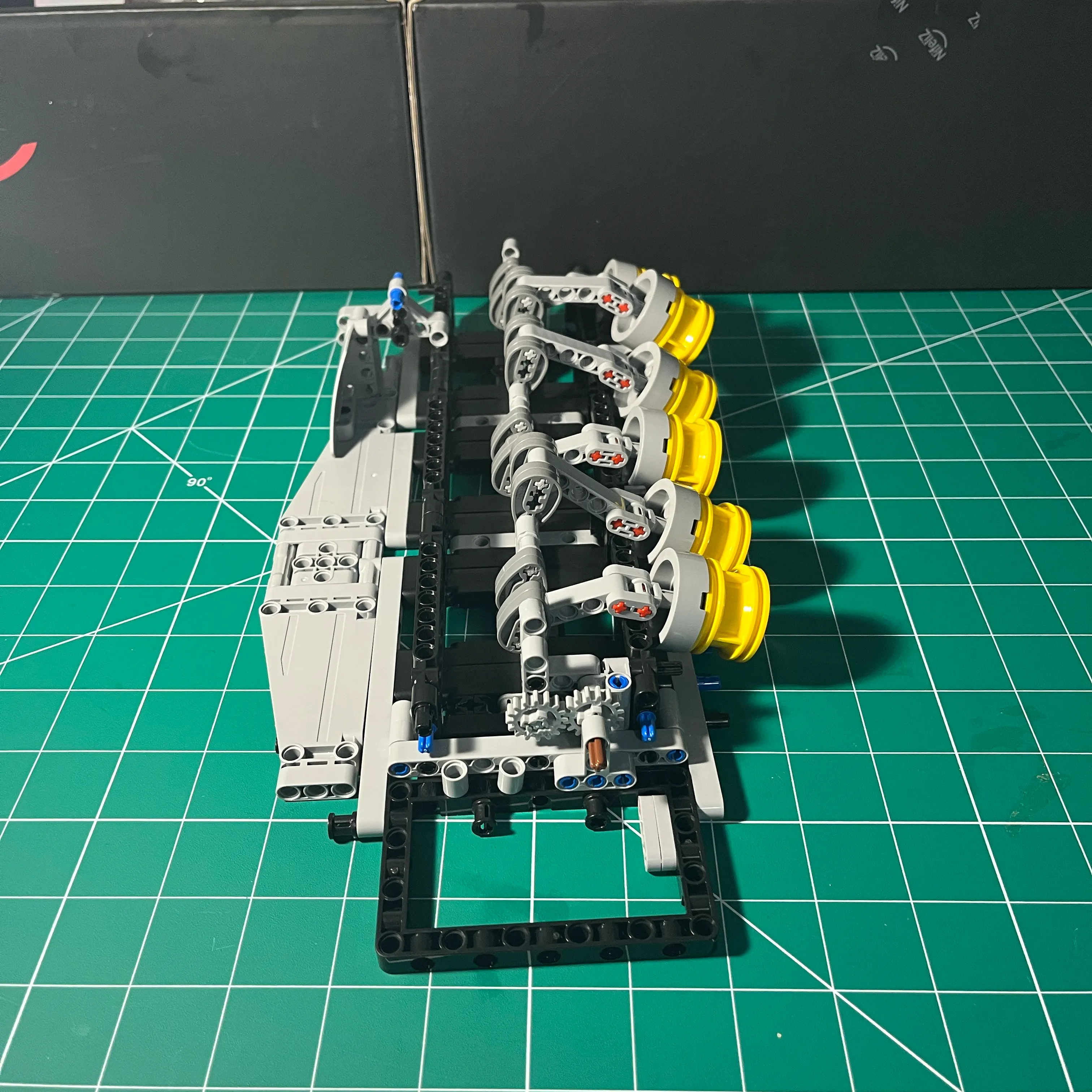
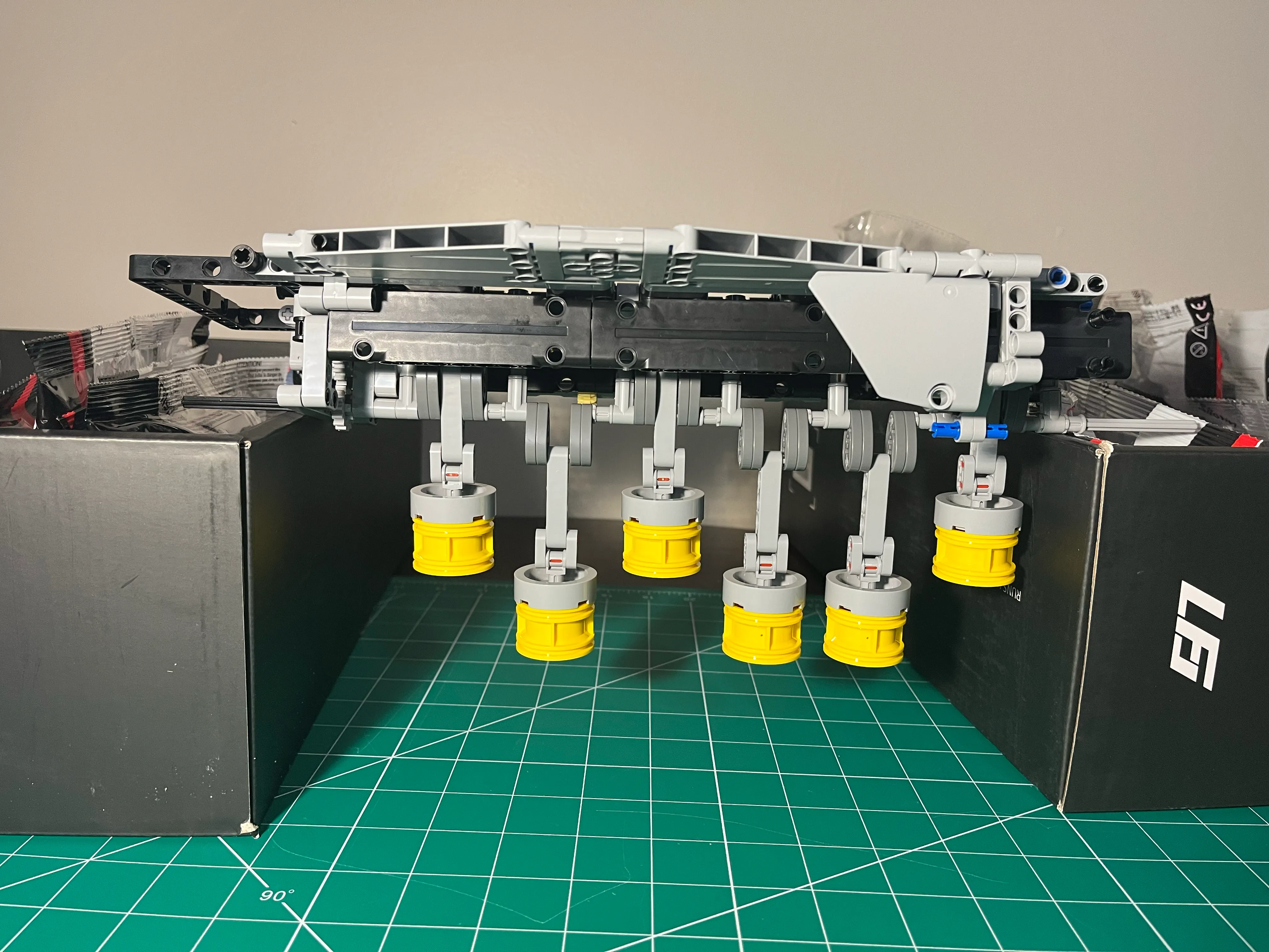
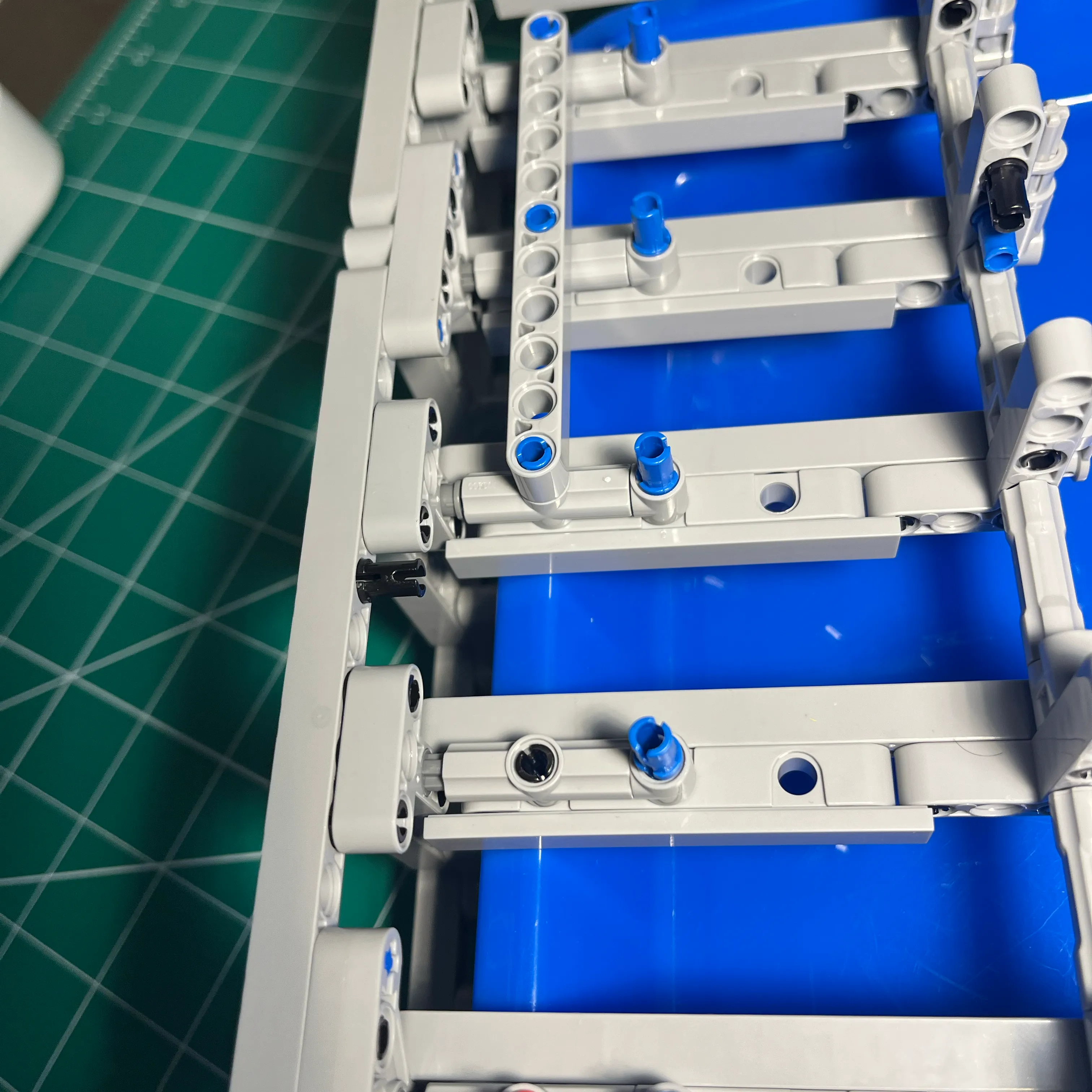
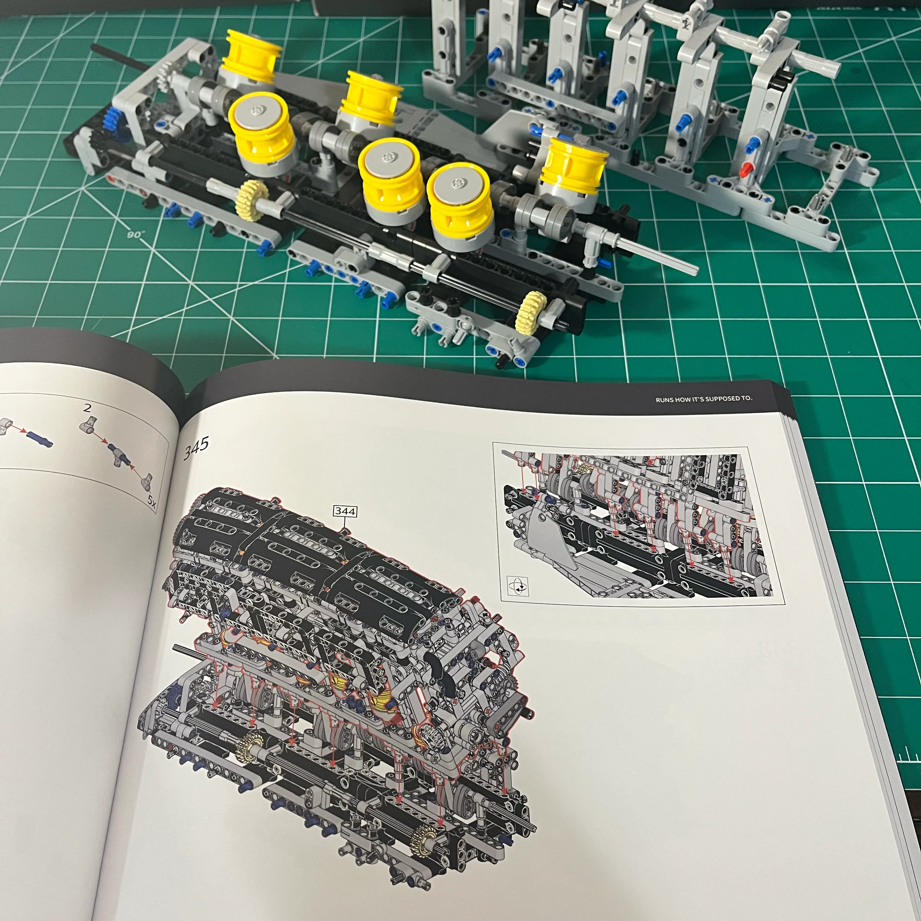
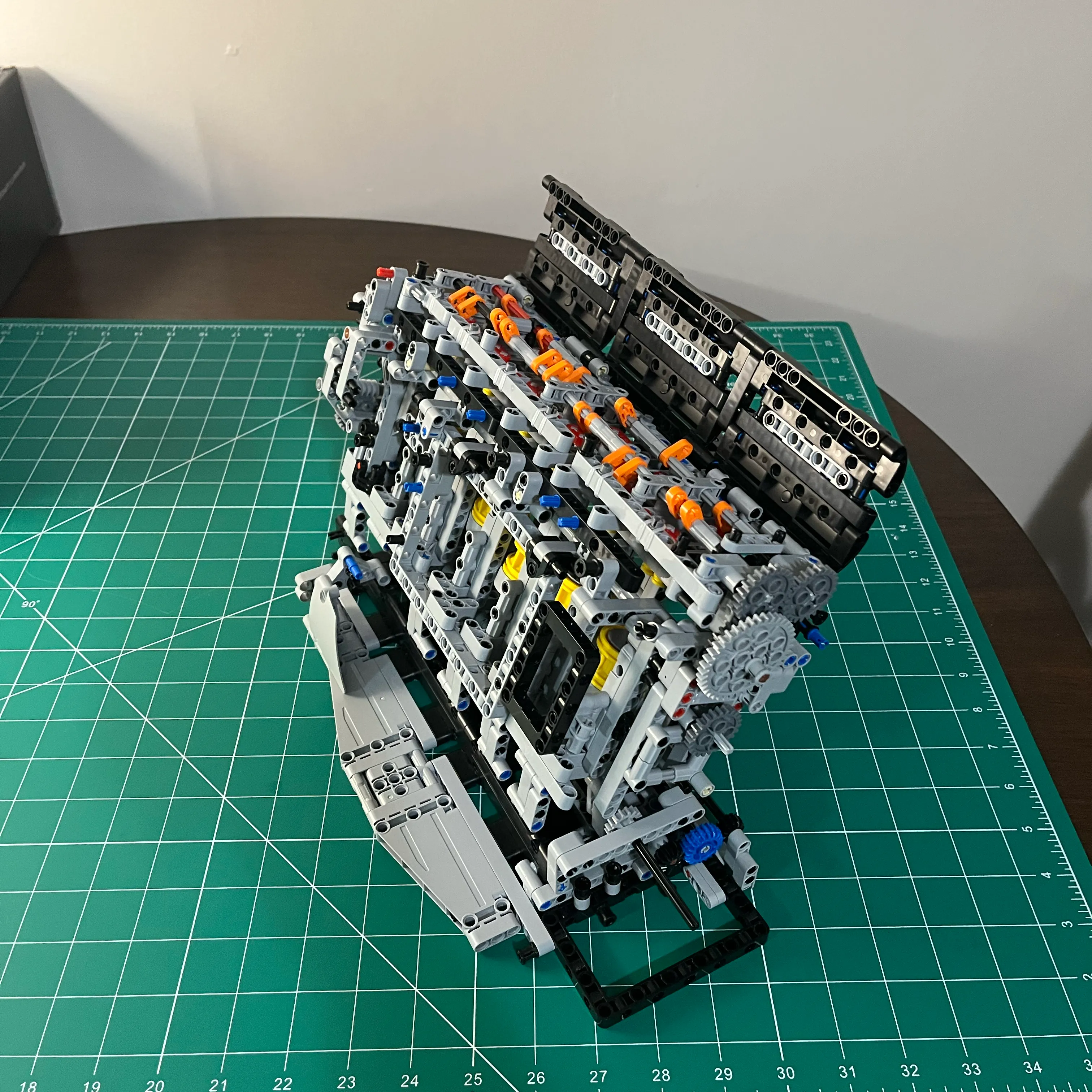
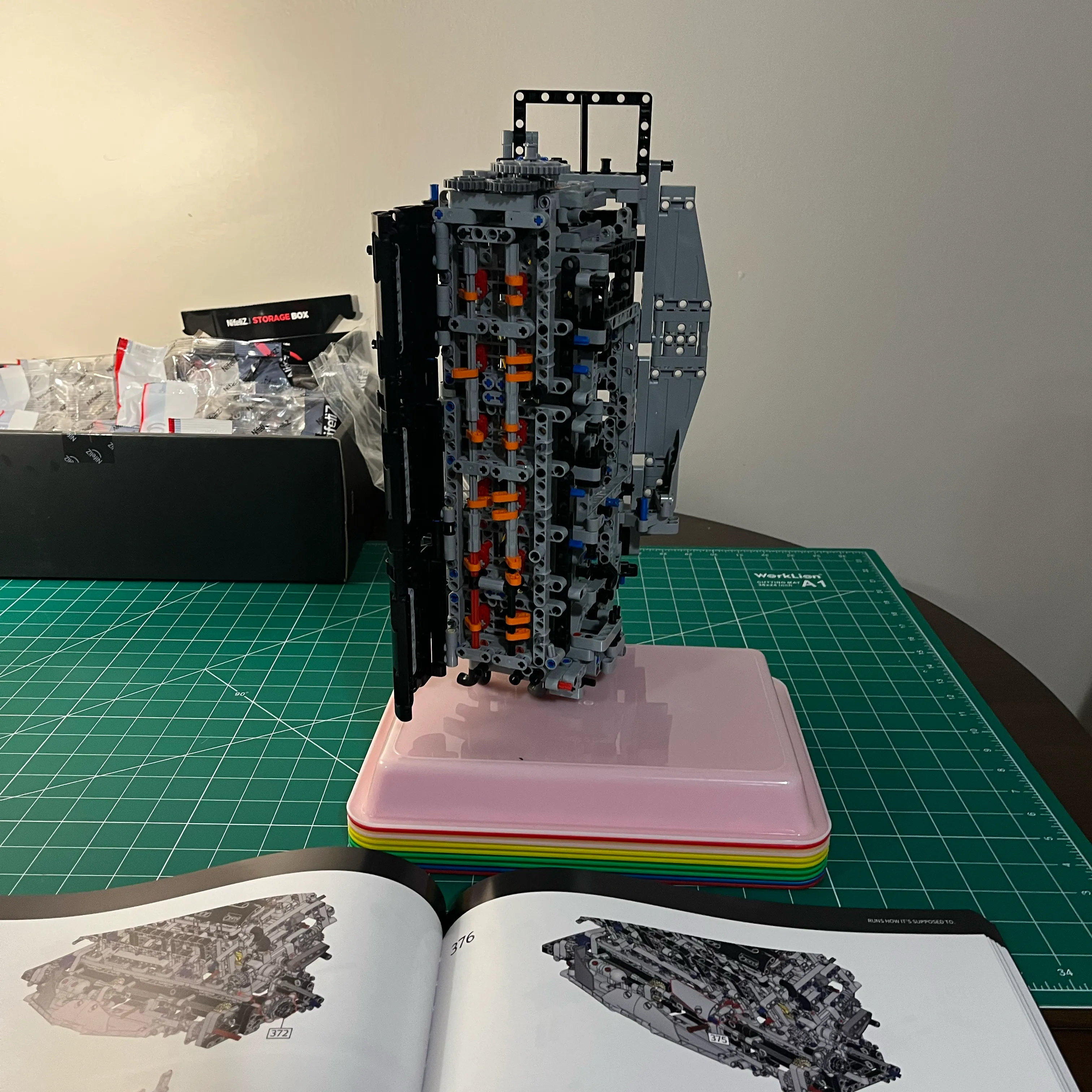
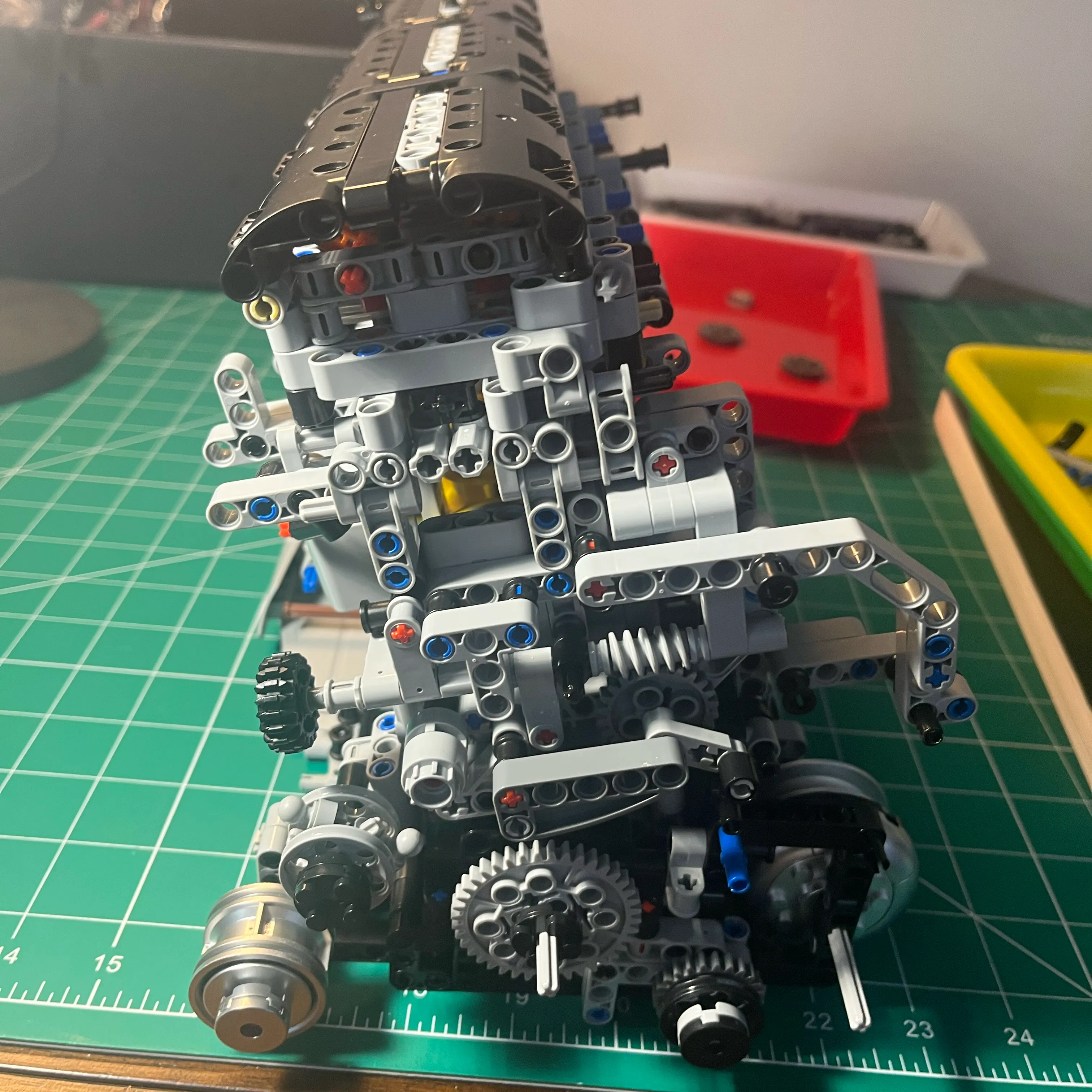
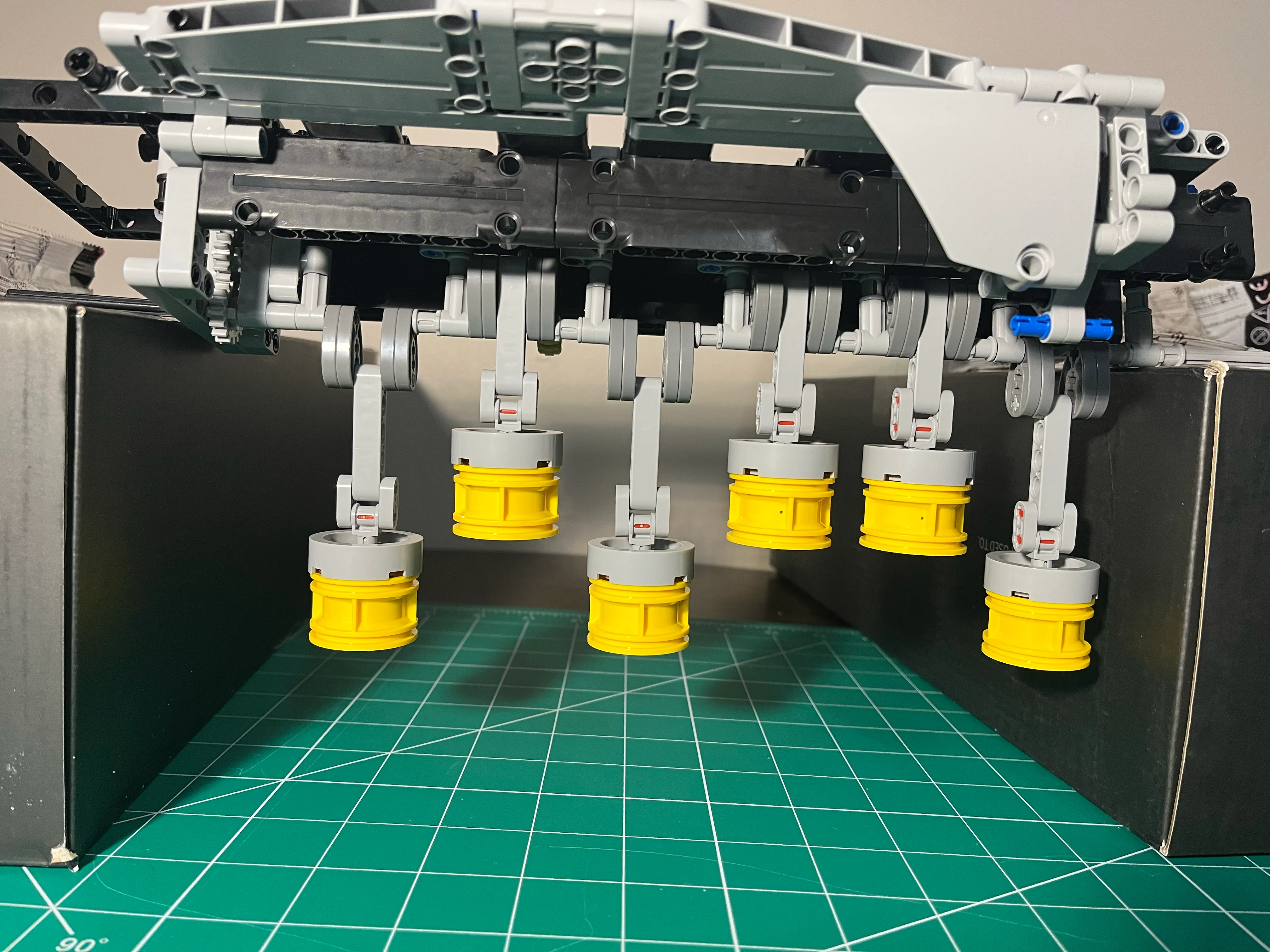
The other side of the engine block had better visibility, and gives a nice view of the pistons! I still couldn’t see where the binding was happening, but I could hear it.
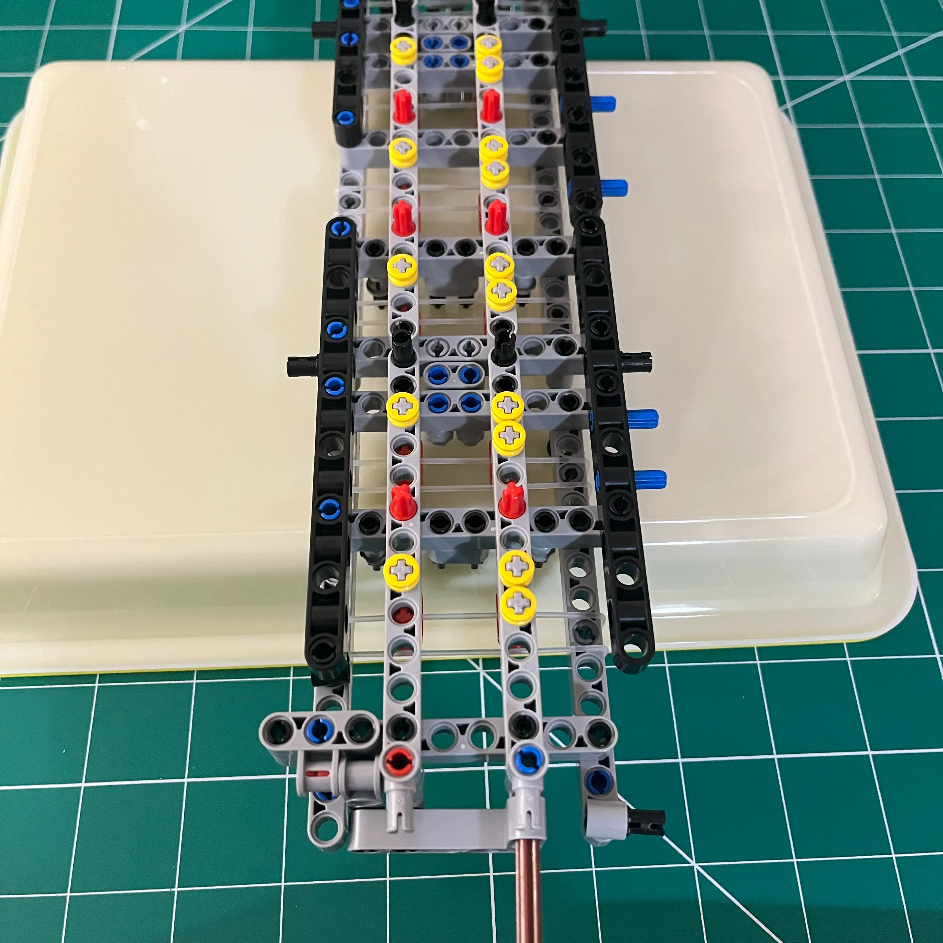
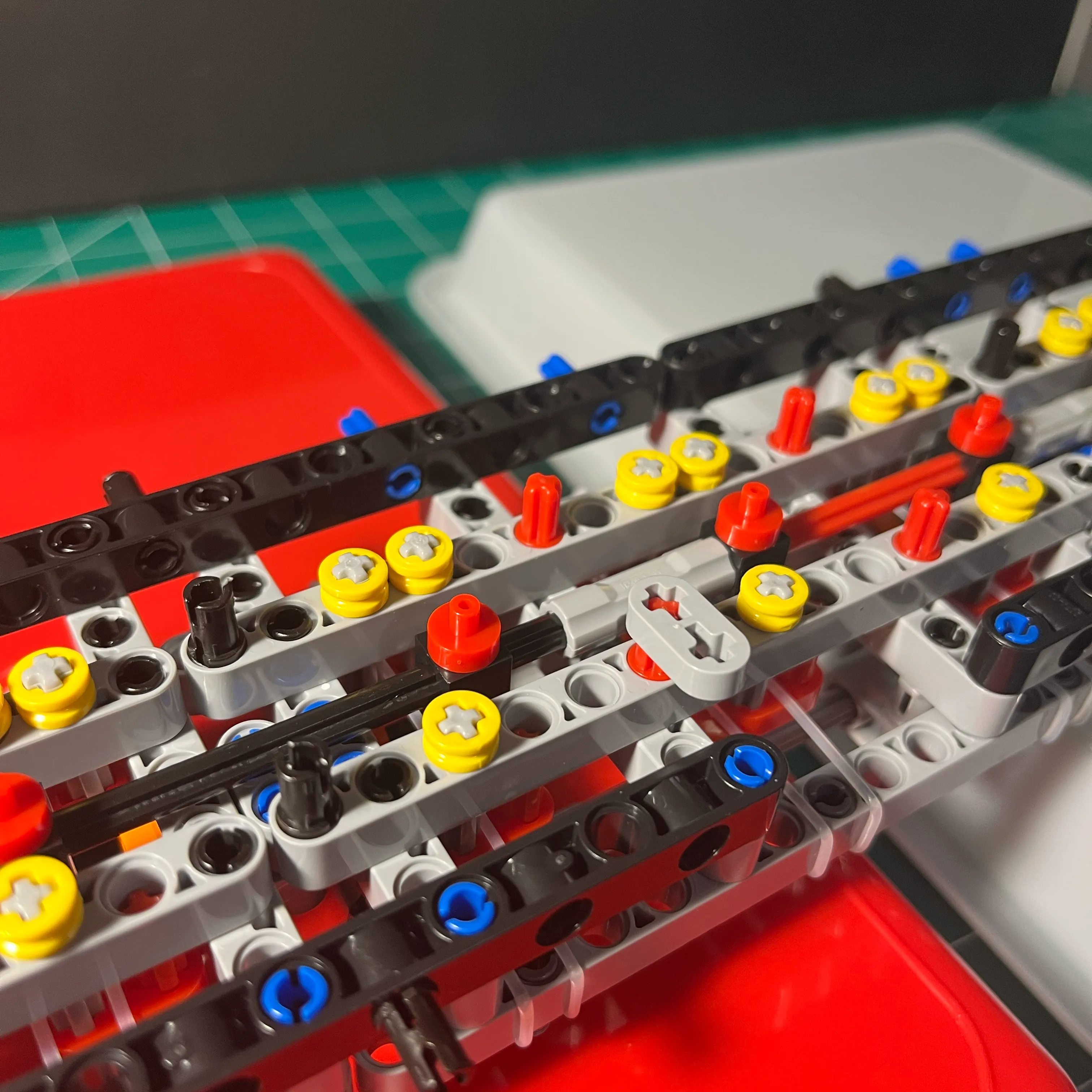
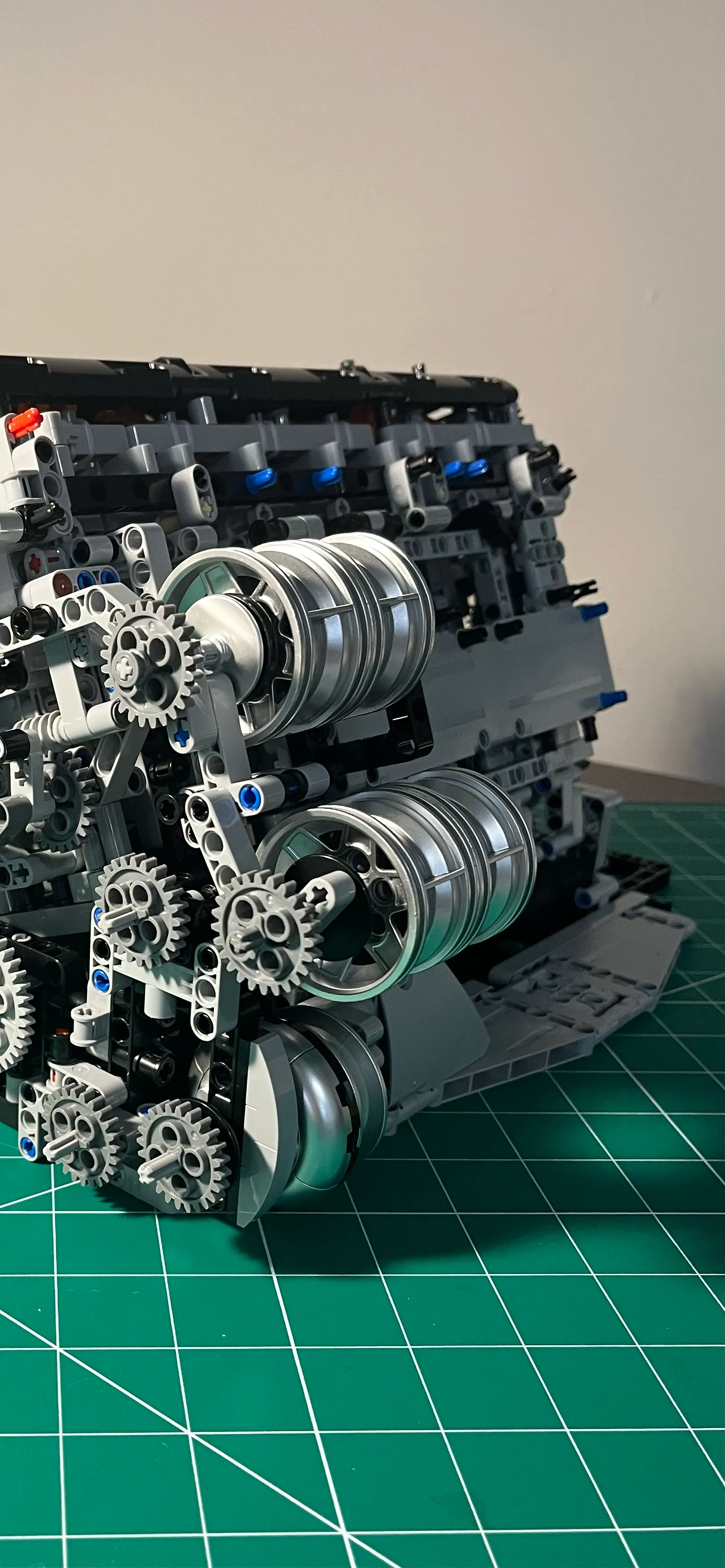
Here’s a view of the crank lobes and piston, where I’m starting to see where the binding is happening. Some crank lobes were hitting engine block cross members.
Here’s another view of a crank lobe that I aligned so that there was enough clearance between the crank lobe and the engine block cross member.
Here’s an example where a crank lobe was hitting the engine block cross member.
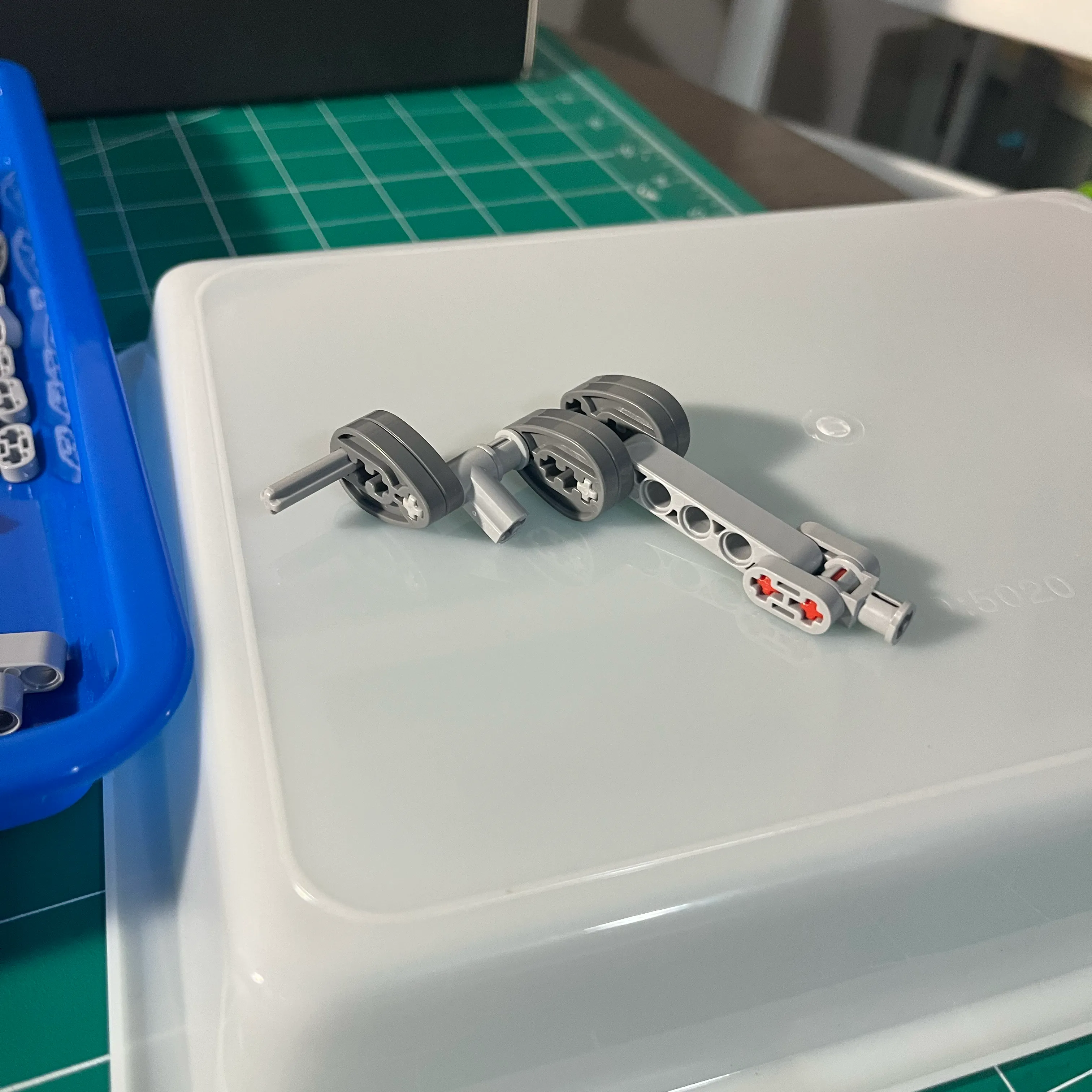
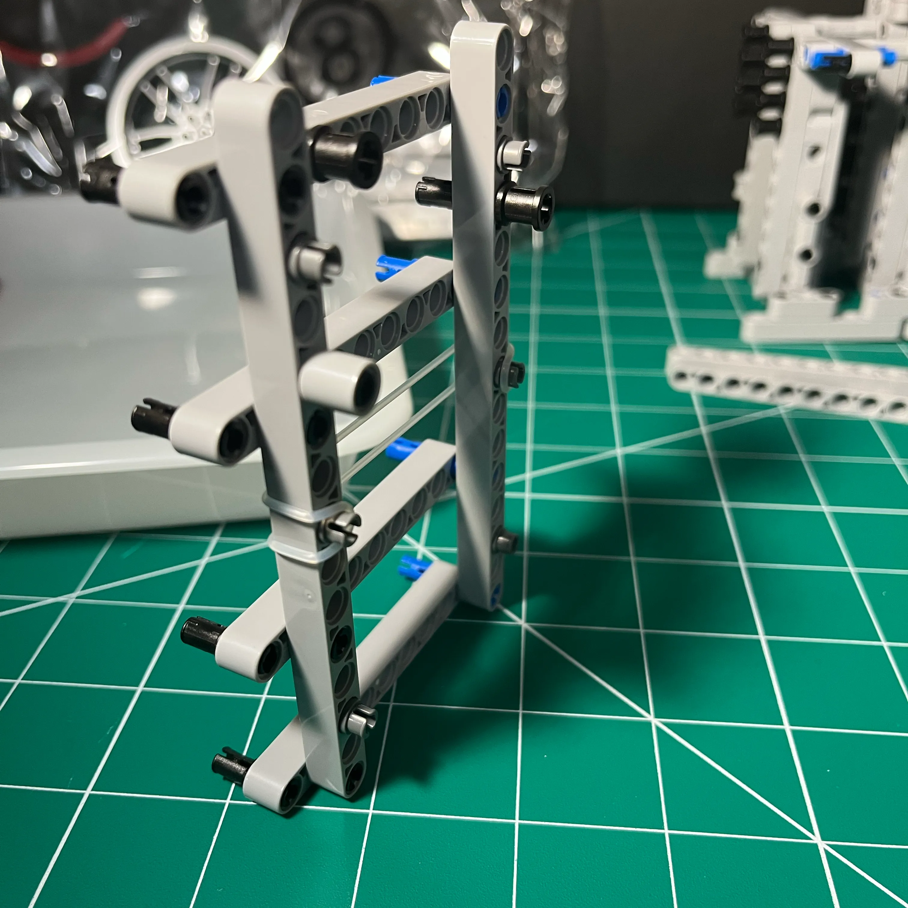
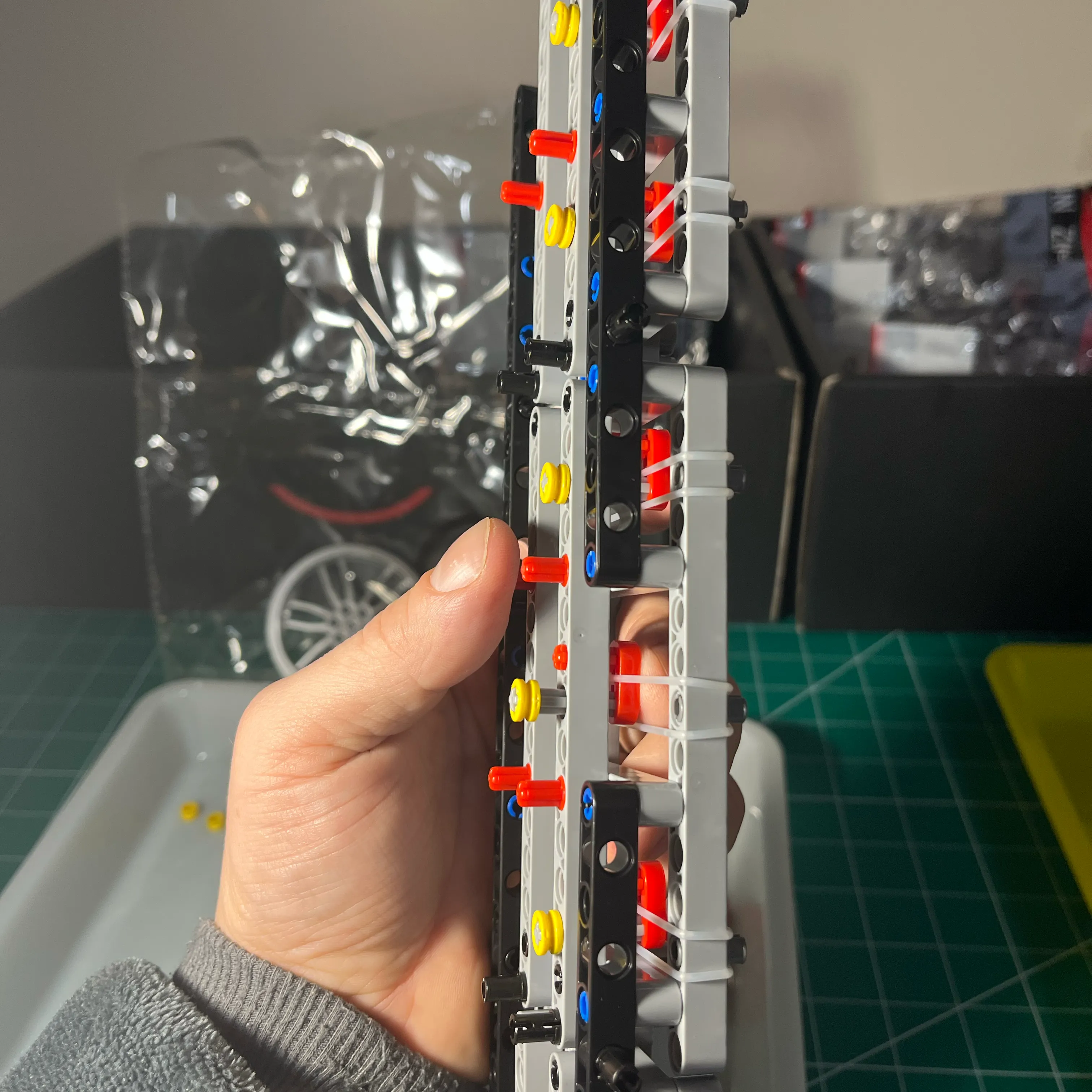
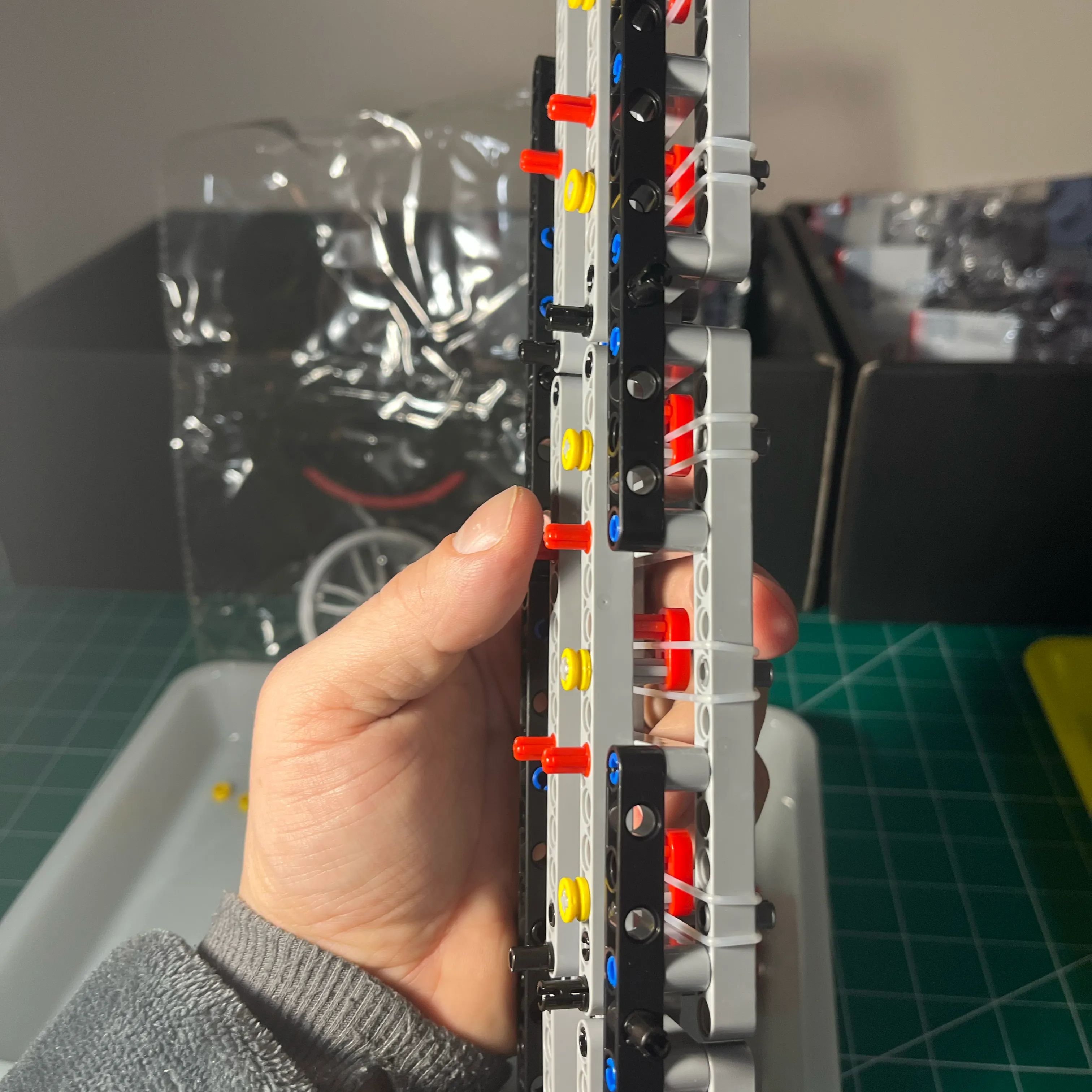
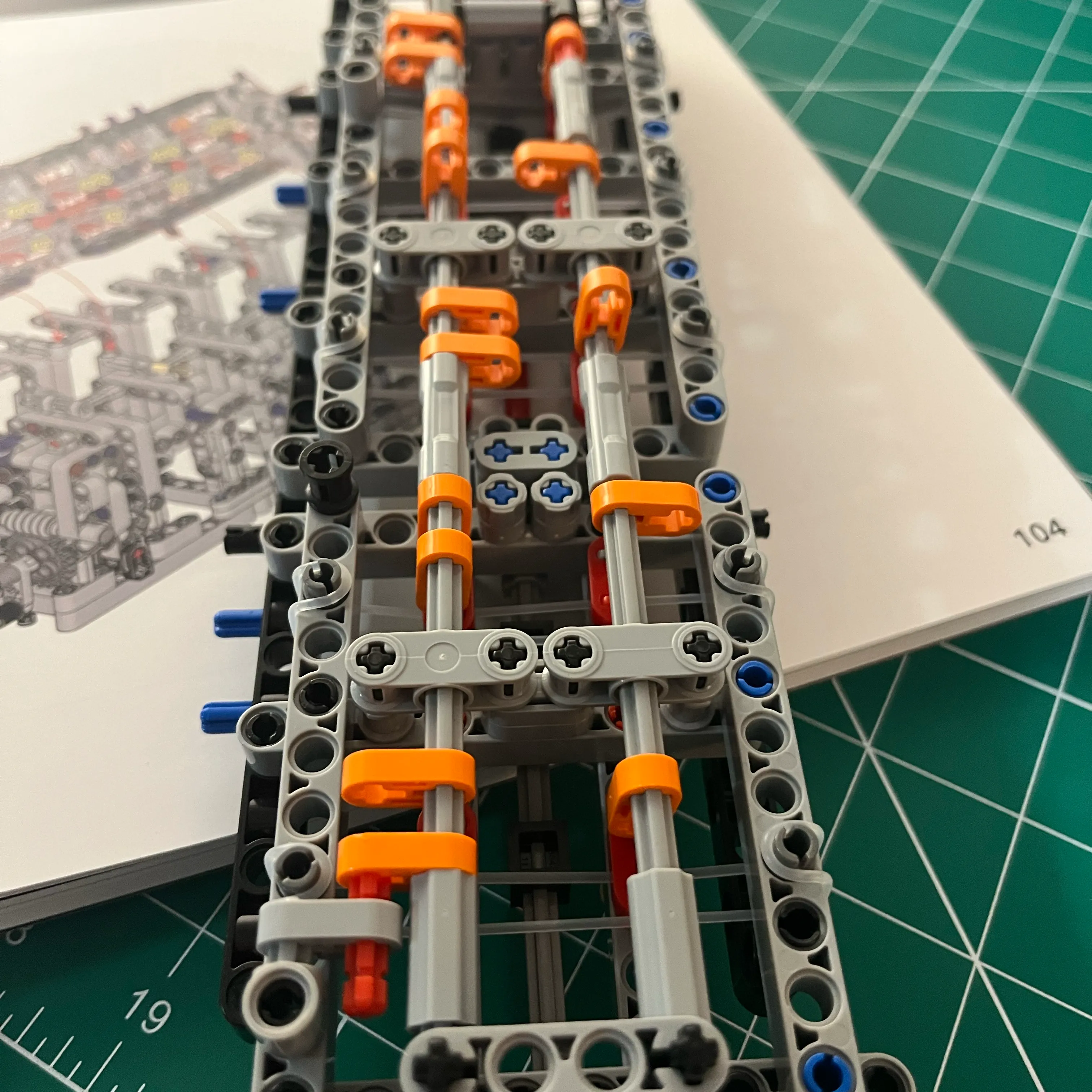
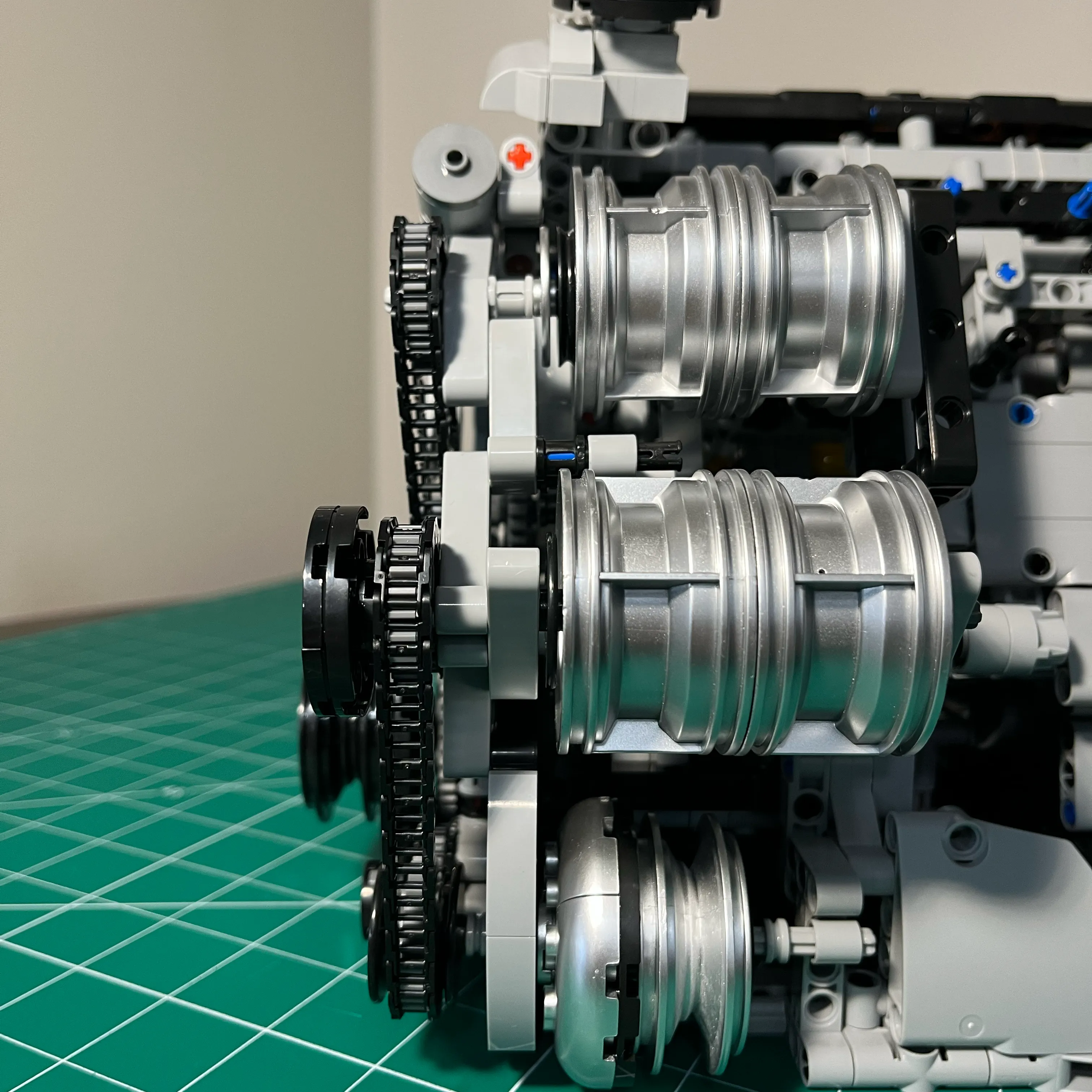
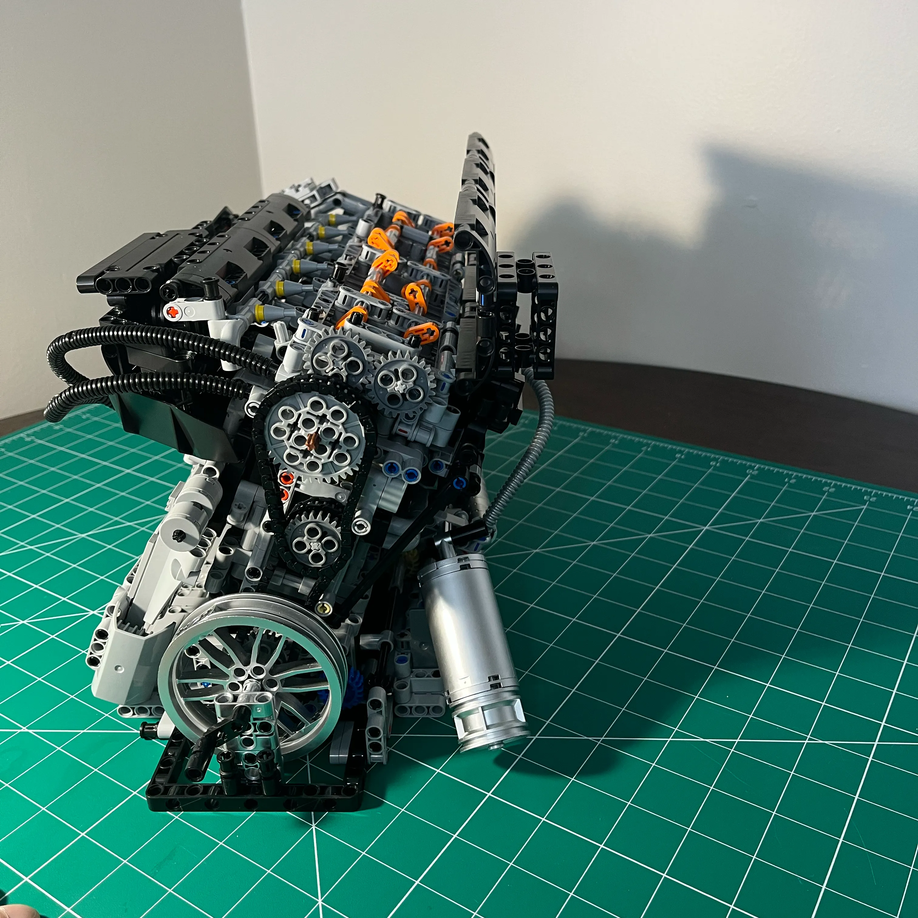
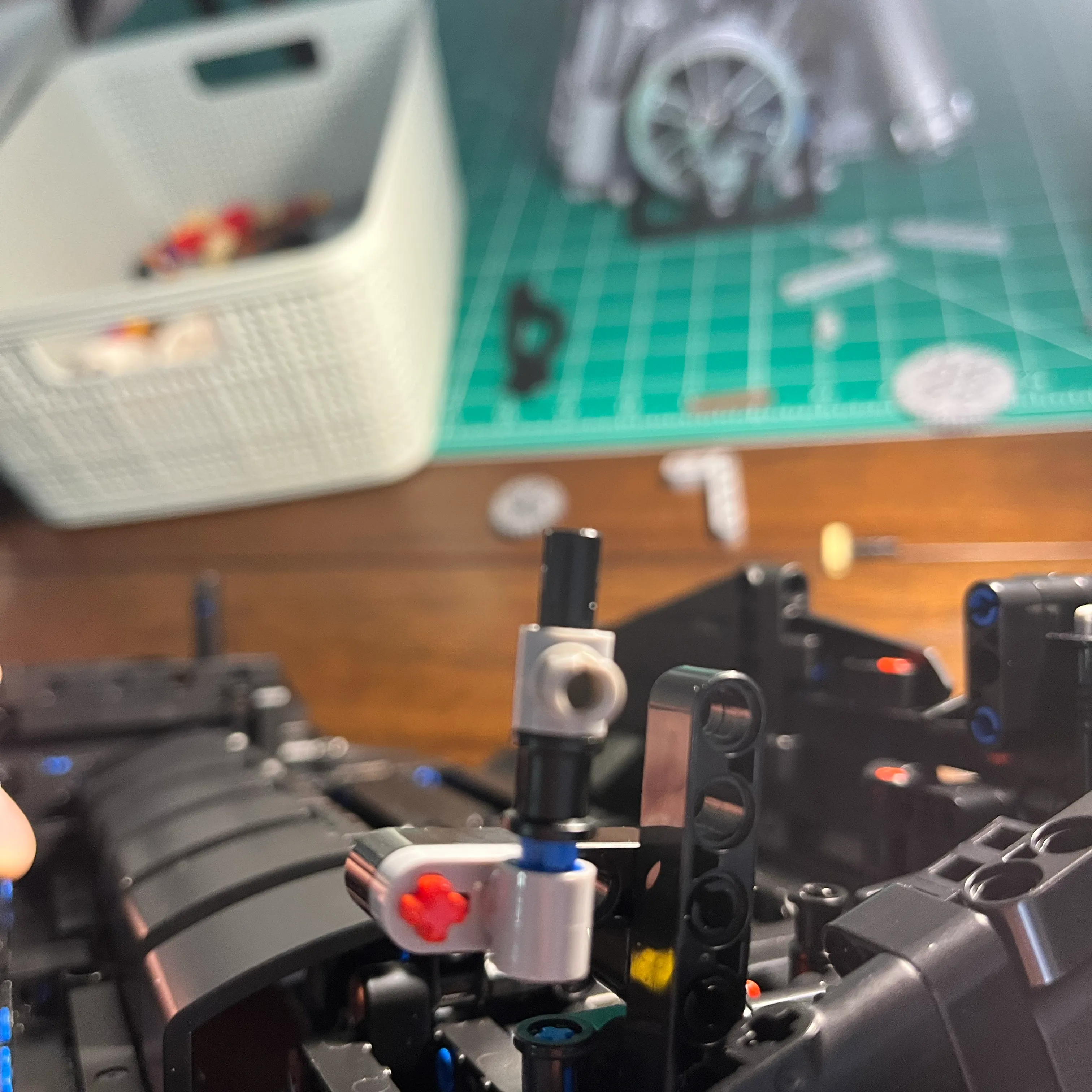
Here’s a look at the crank lobe in cylinder 6 at the back of the engine. A lobe is made up of 2 oval shaped pieces using a connector. The cam lobe is dark gray, and the connector is light gray on the midline of the lobe. If that connector protrudes too far, it can either hit the piston connecting rod, or the engine block cross member.
What I had to do was check each engine block cross member and ensure there was enough clearance between the crank lobe. I also had to check that the connectors were not protruding. This needs to be done iteratively, because adjusting clearance in one cylinder can change clearances in other cylinders. There isn’t a whole lot of room for adjustment.
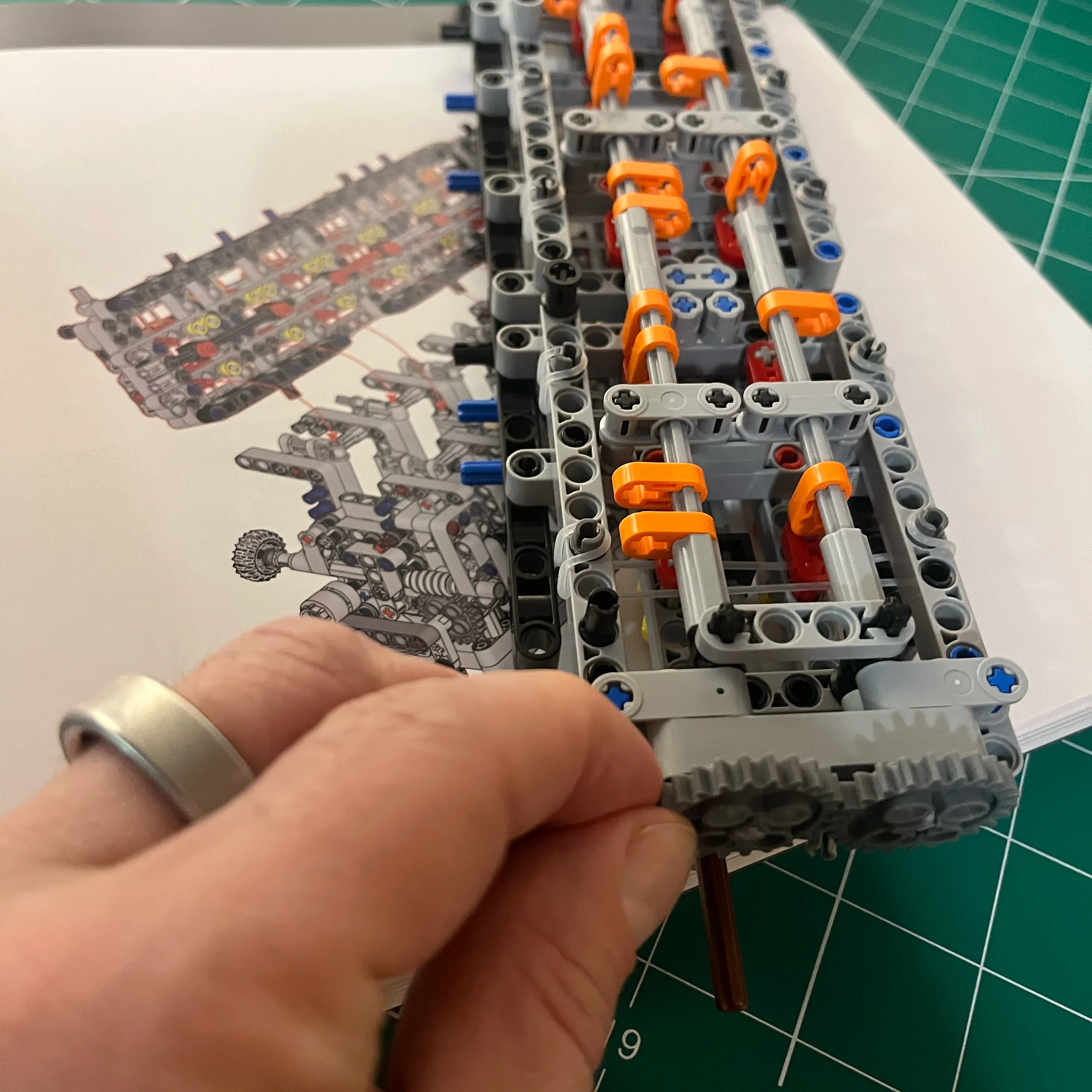
During assembly, the alignments and clearances can change as components are moved around. Adding the head, attaching the block to the frame, attaching the gears are all examples of things that can change clearances ever so slightly. The crank can move forward and backward during assembly. Engine block structural members can move around slightly until they are fully aligned / seated.
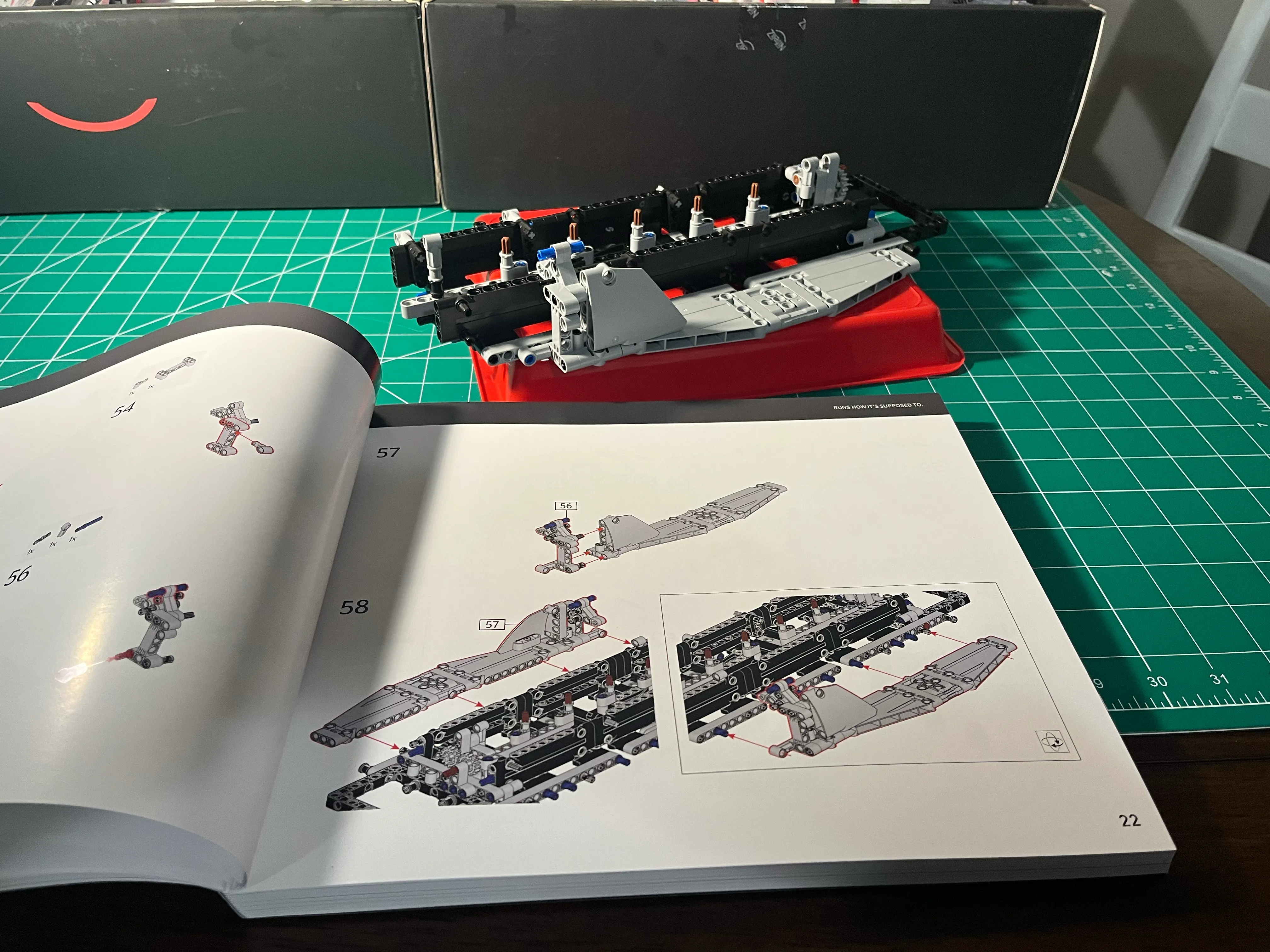
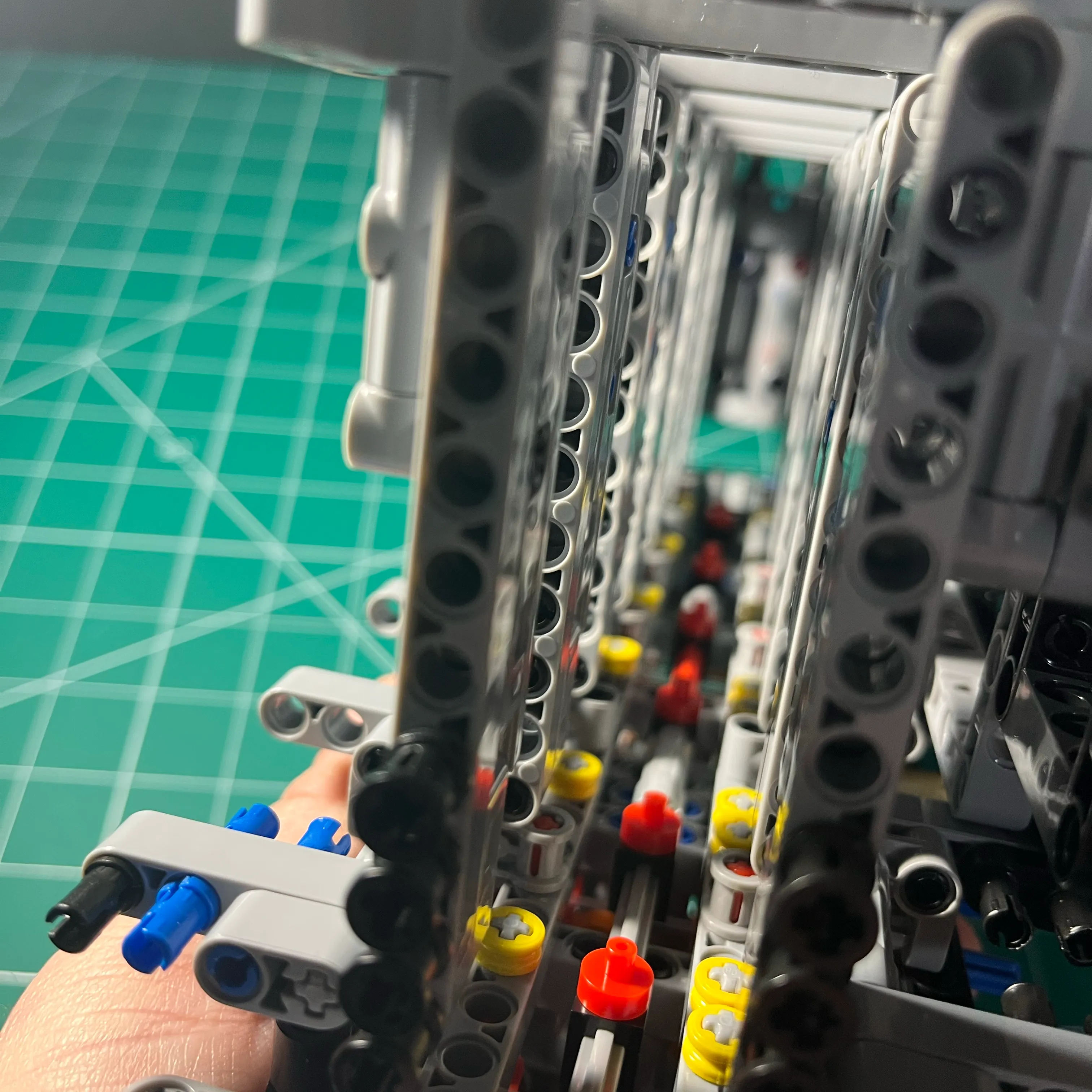
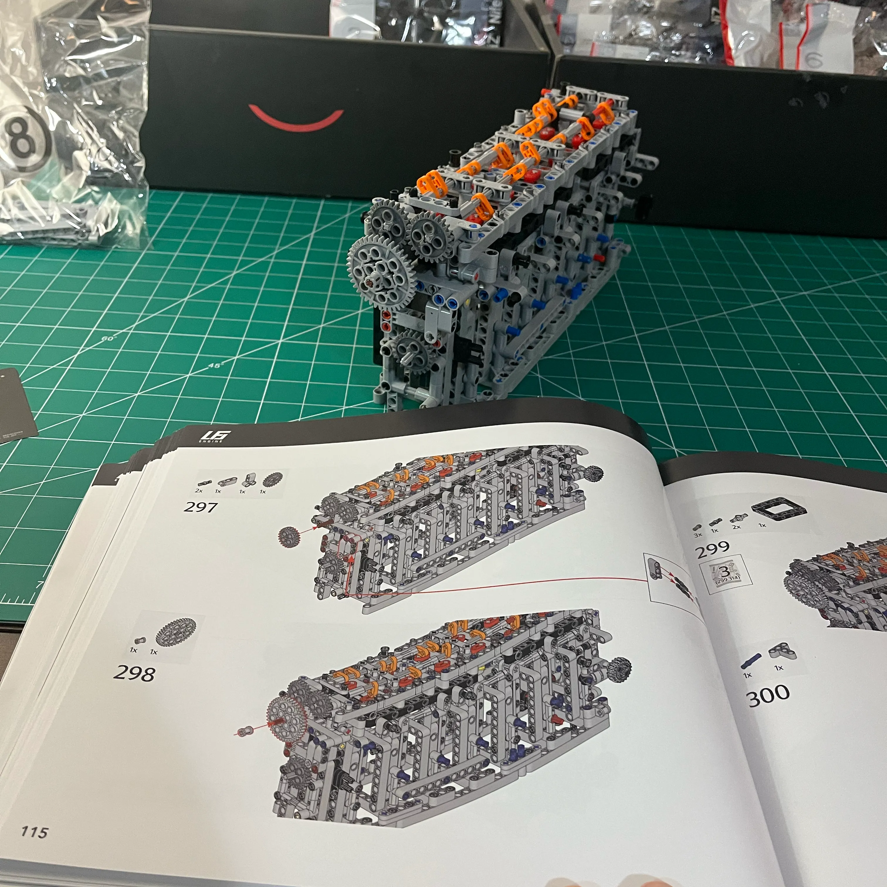
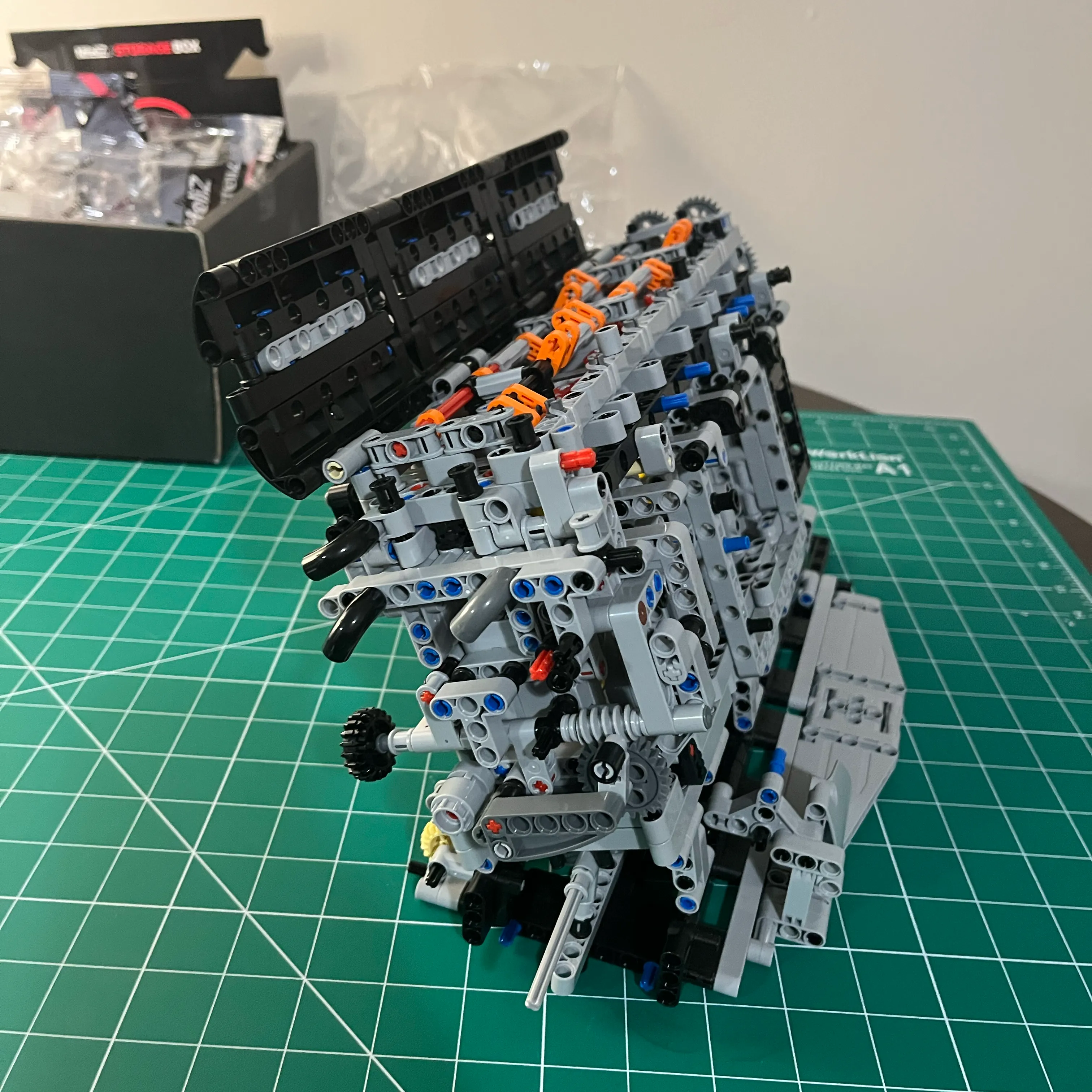
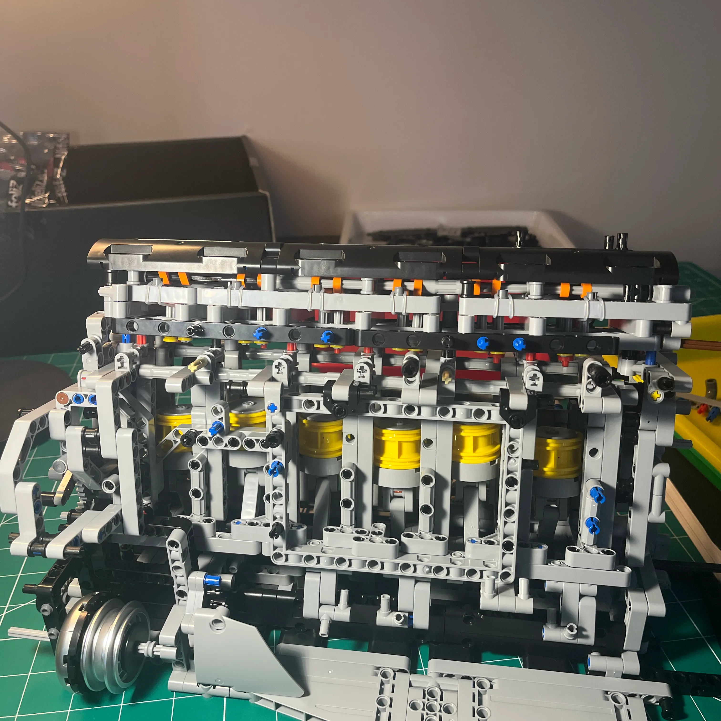
Here’s some footage once I tore down the engine to address the alignment issues. It would have been nice to have this procedure as part of the assembly process, to save the future aggravation.
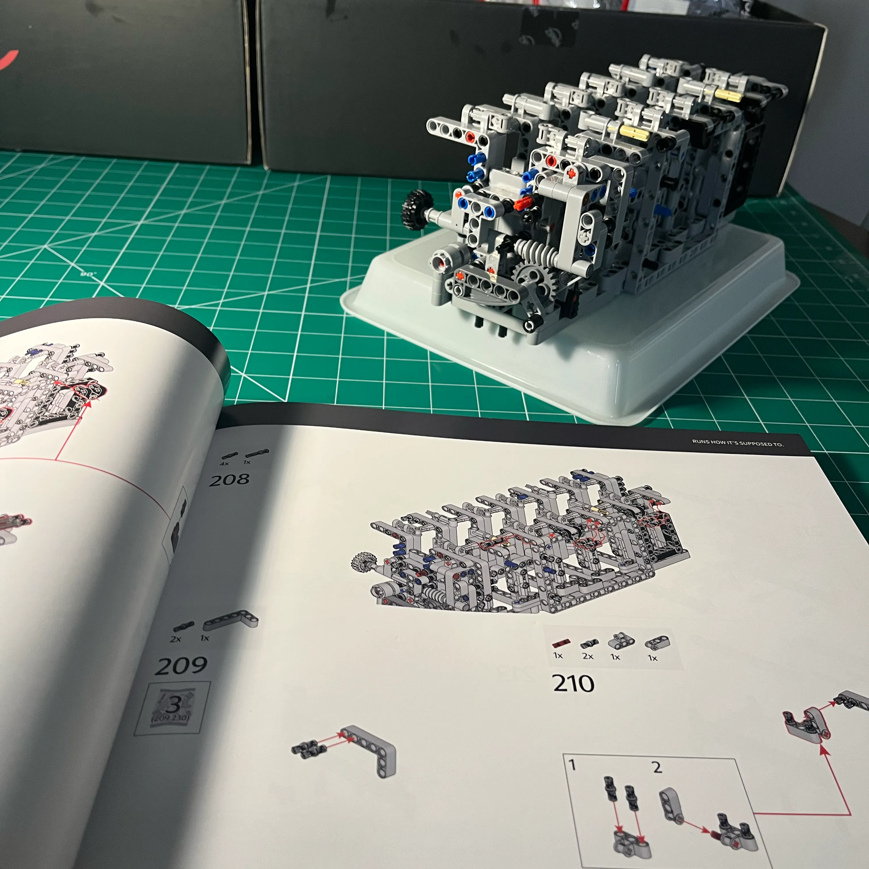
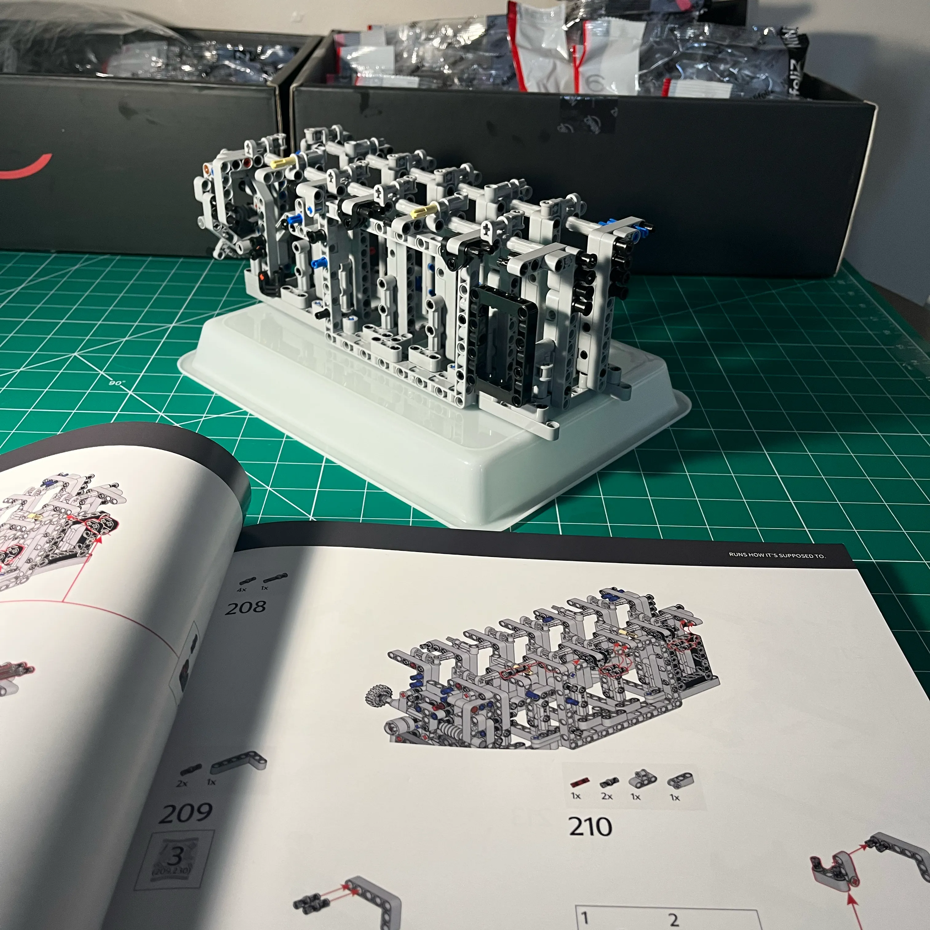
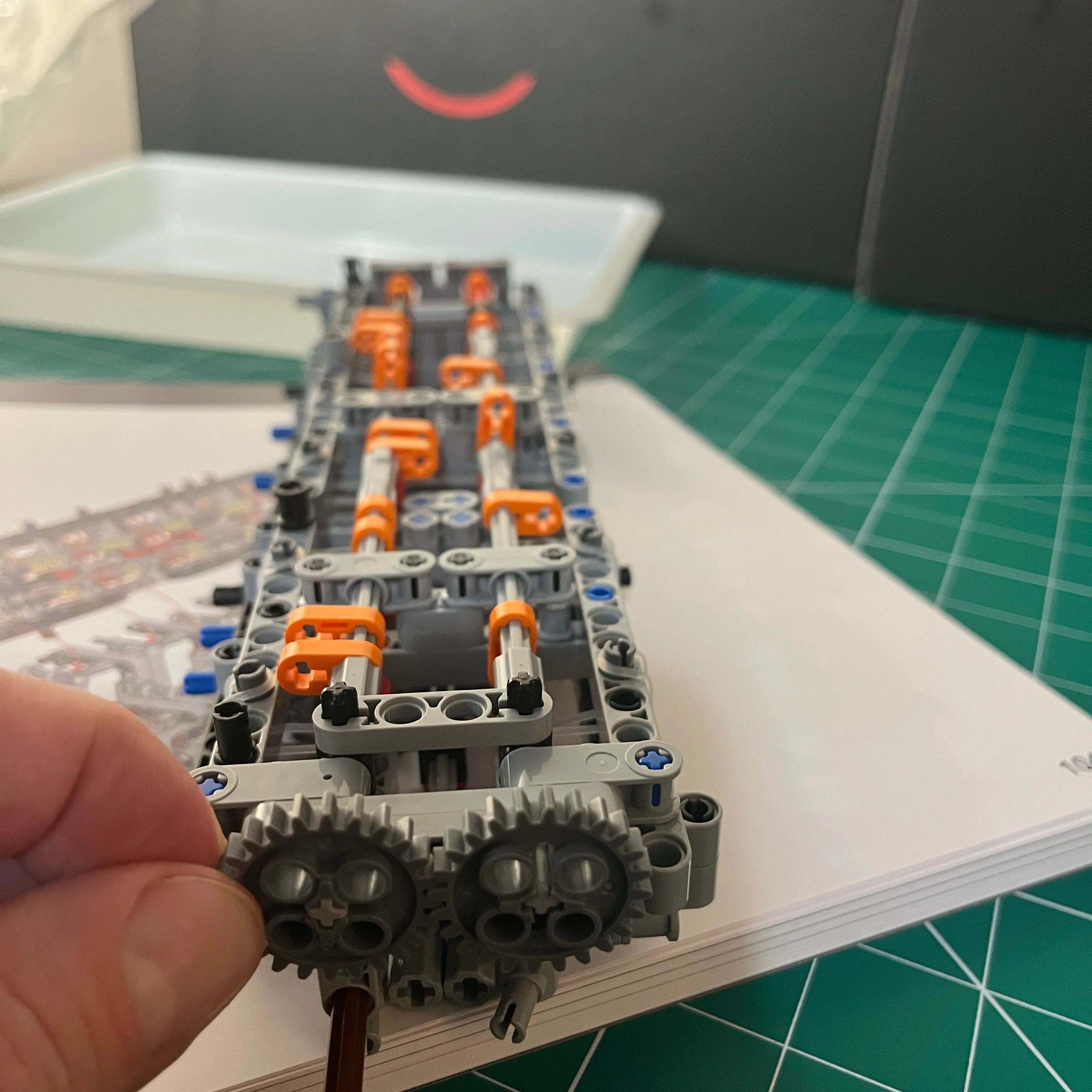
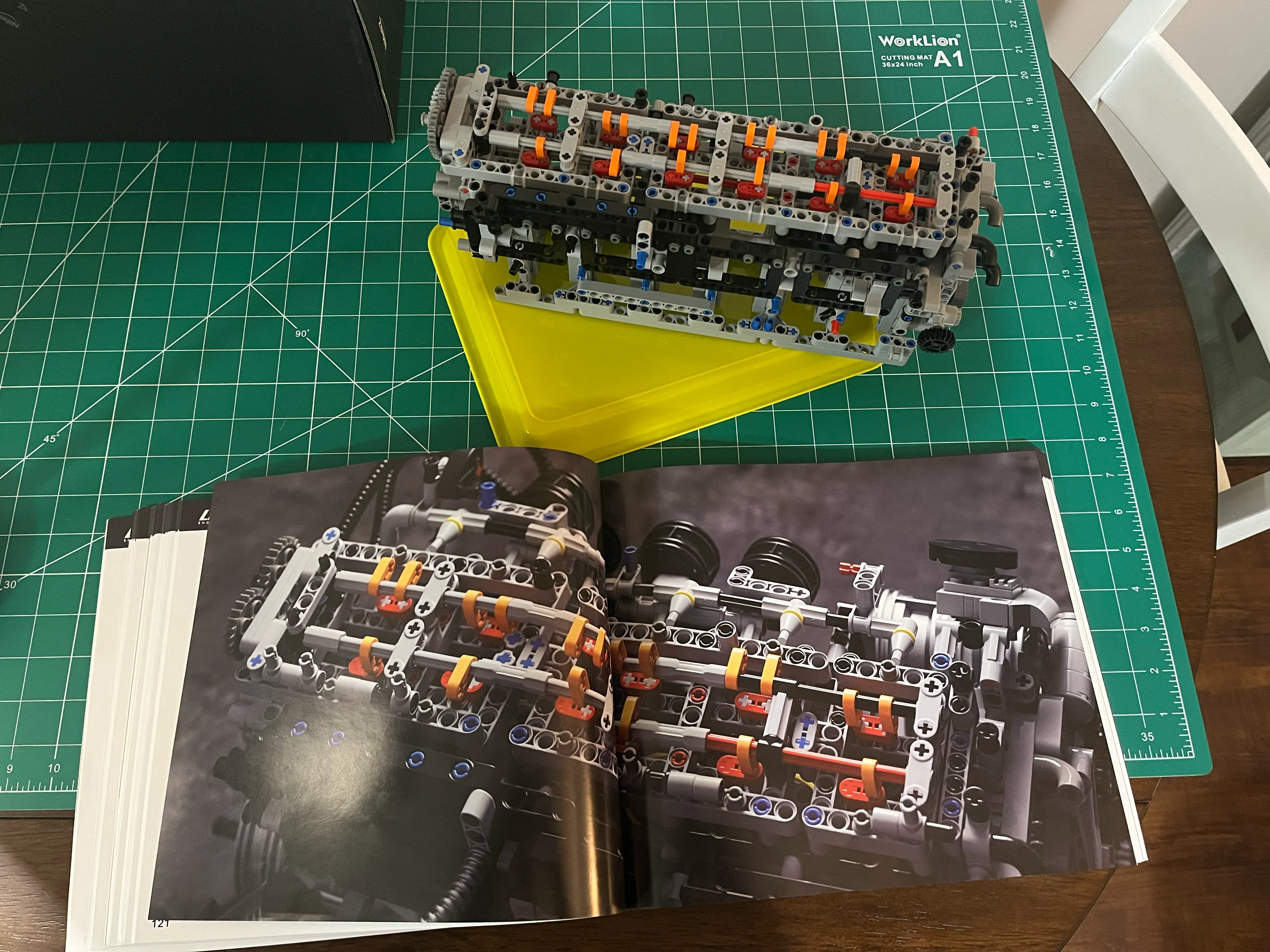
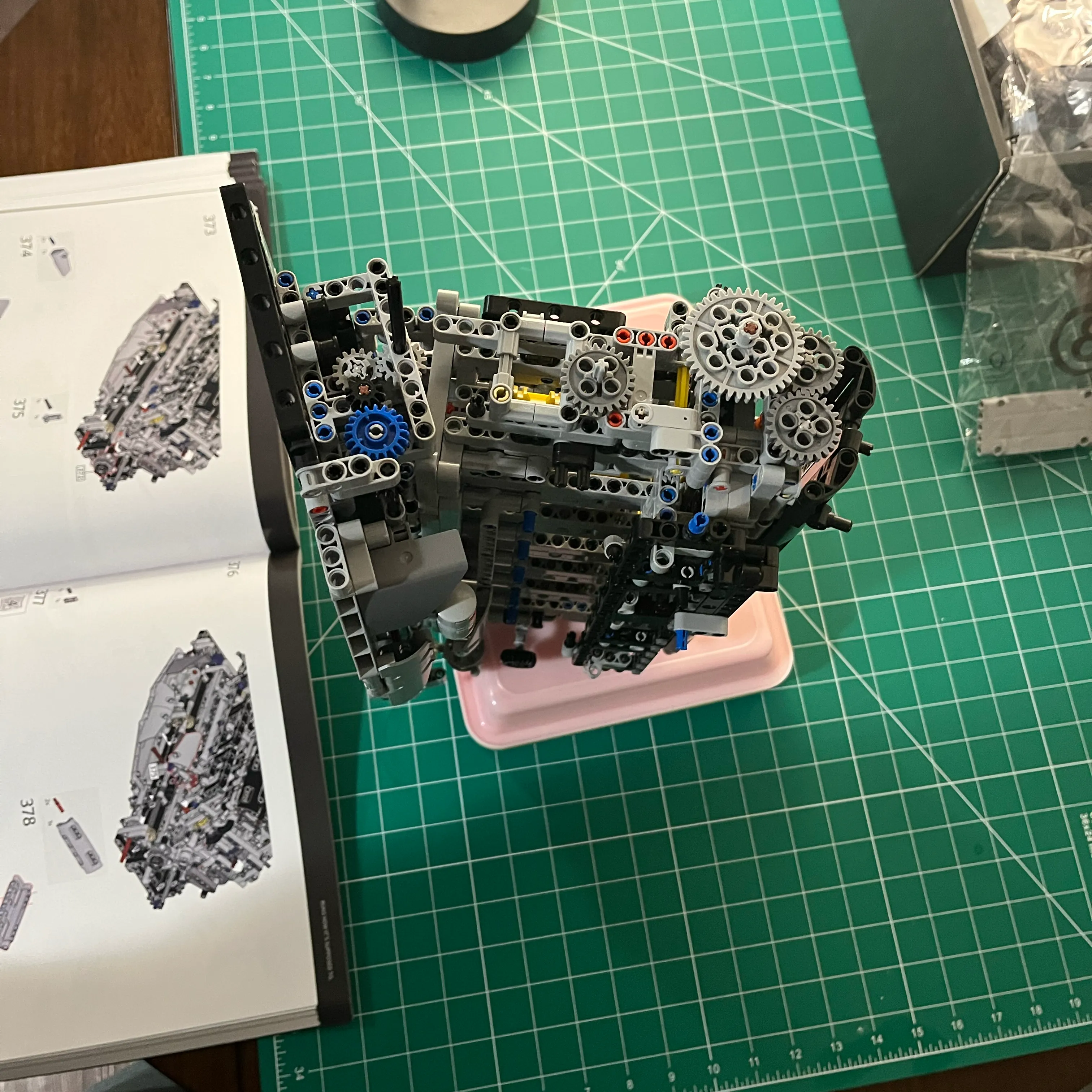
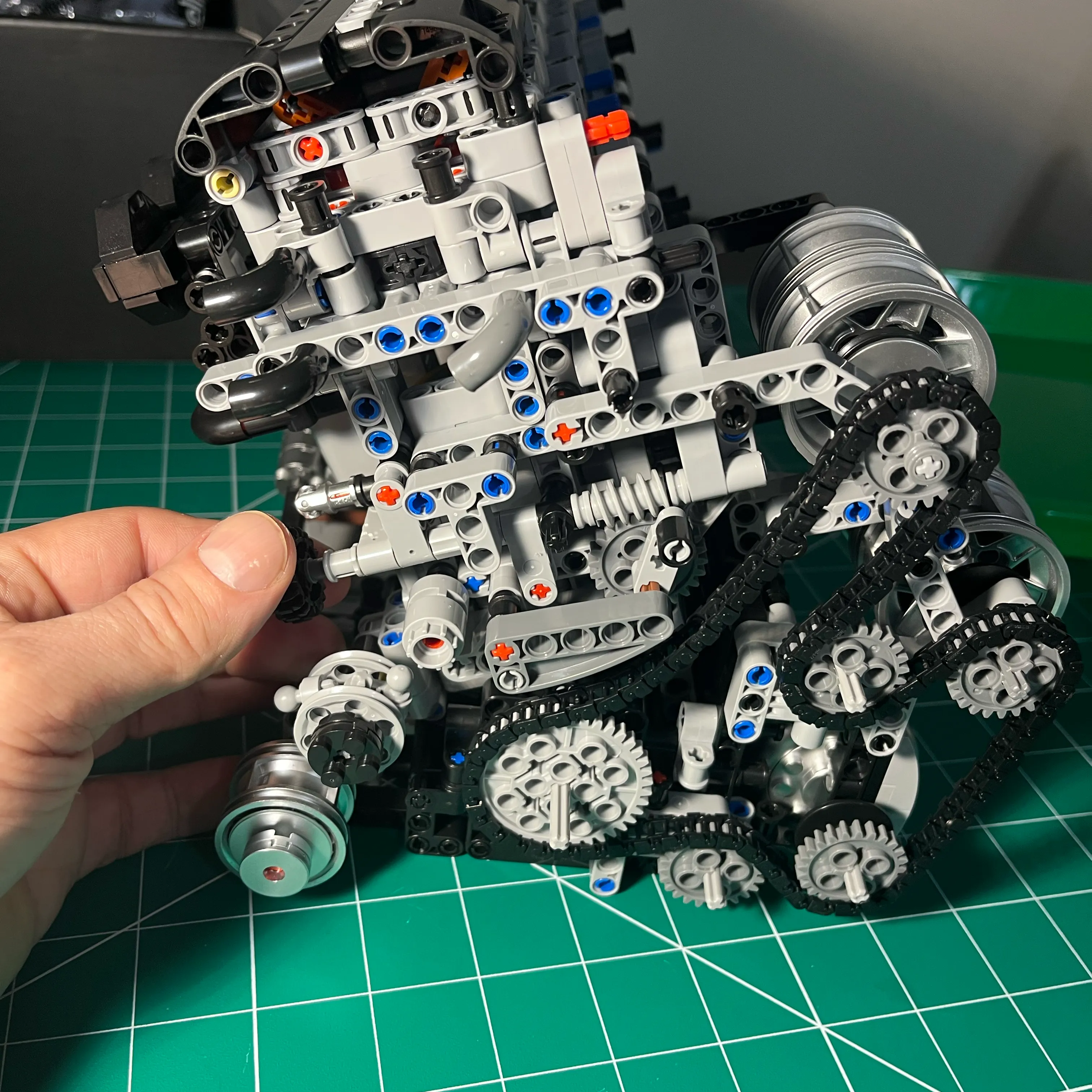
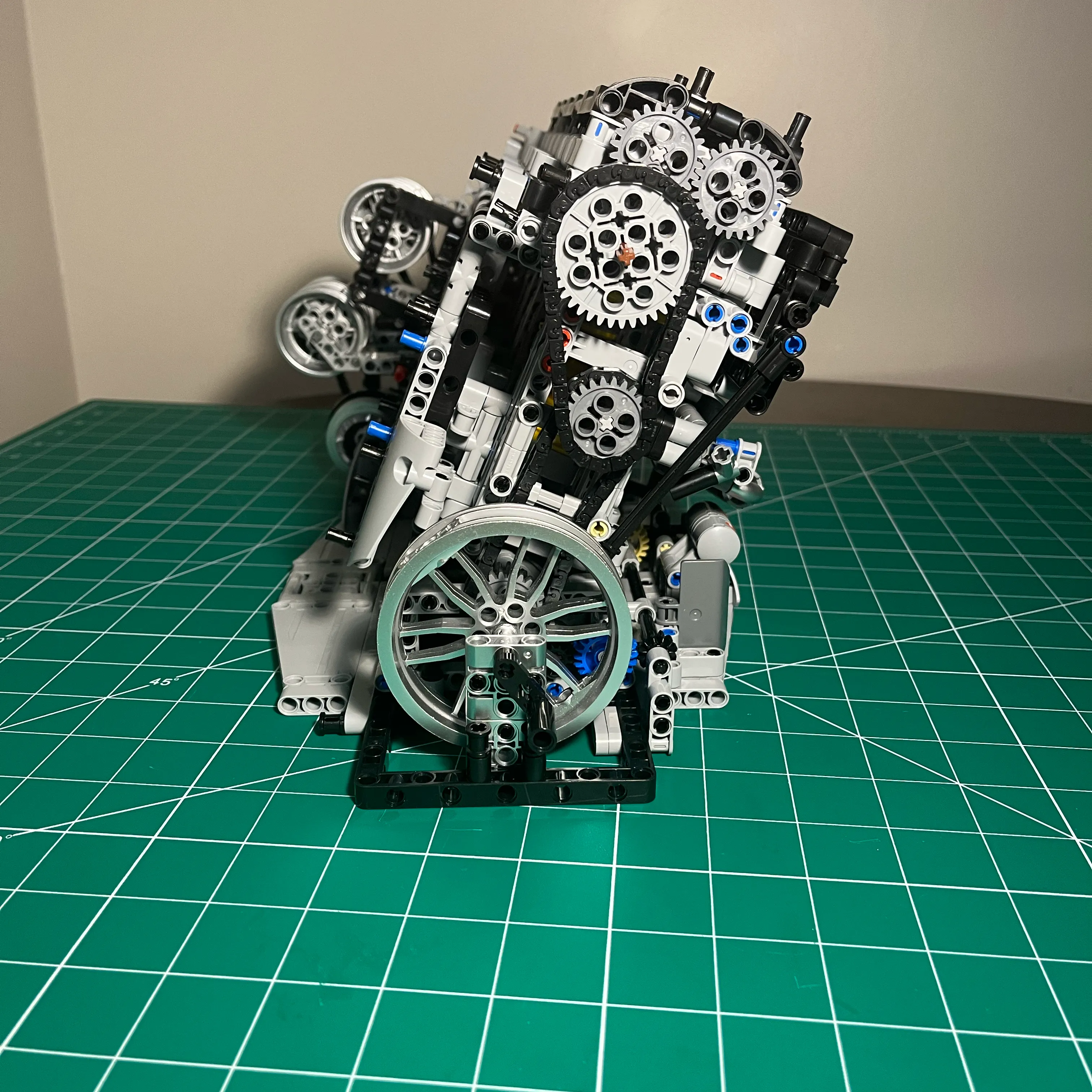
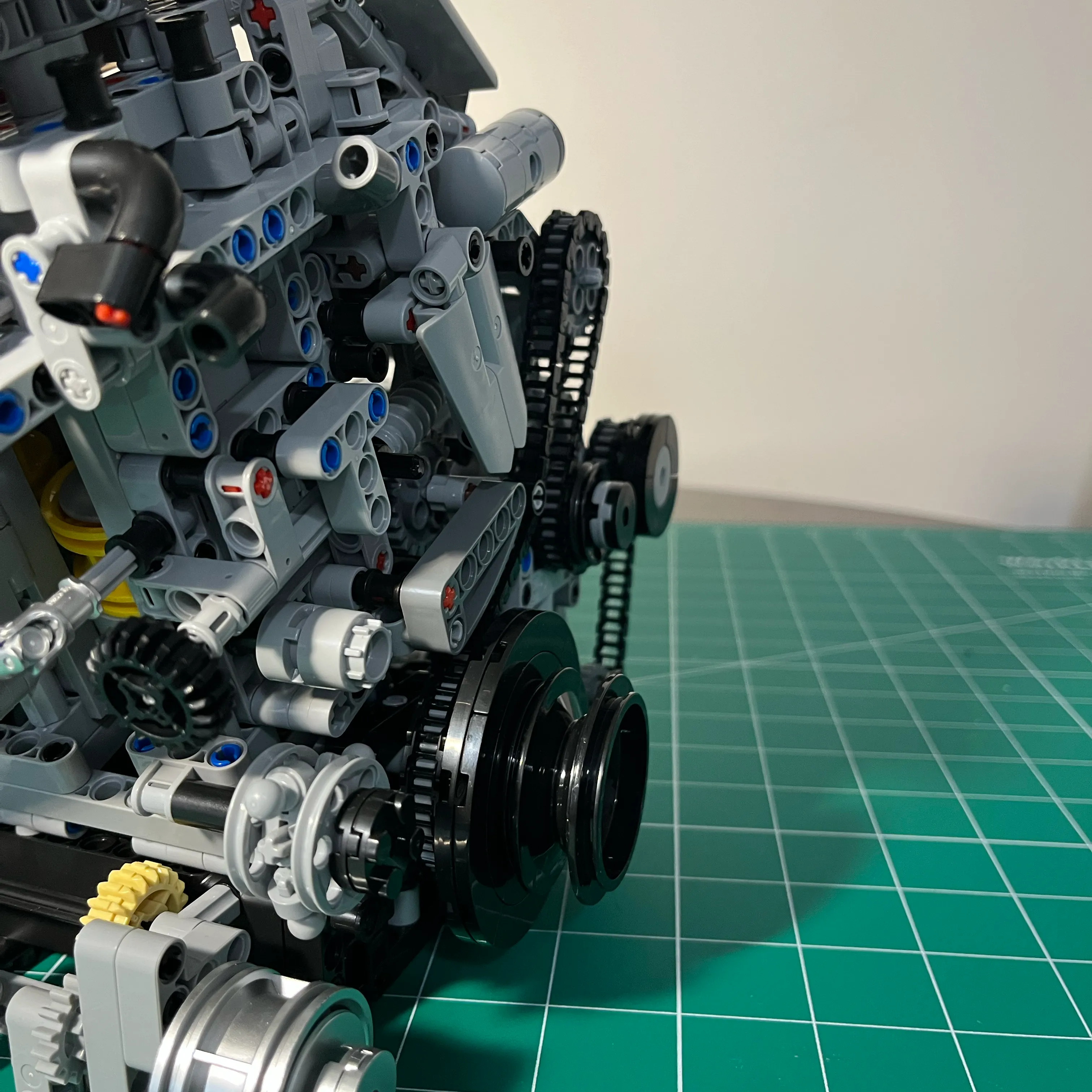
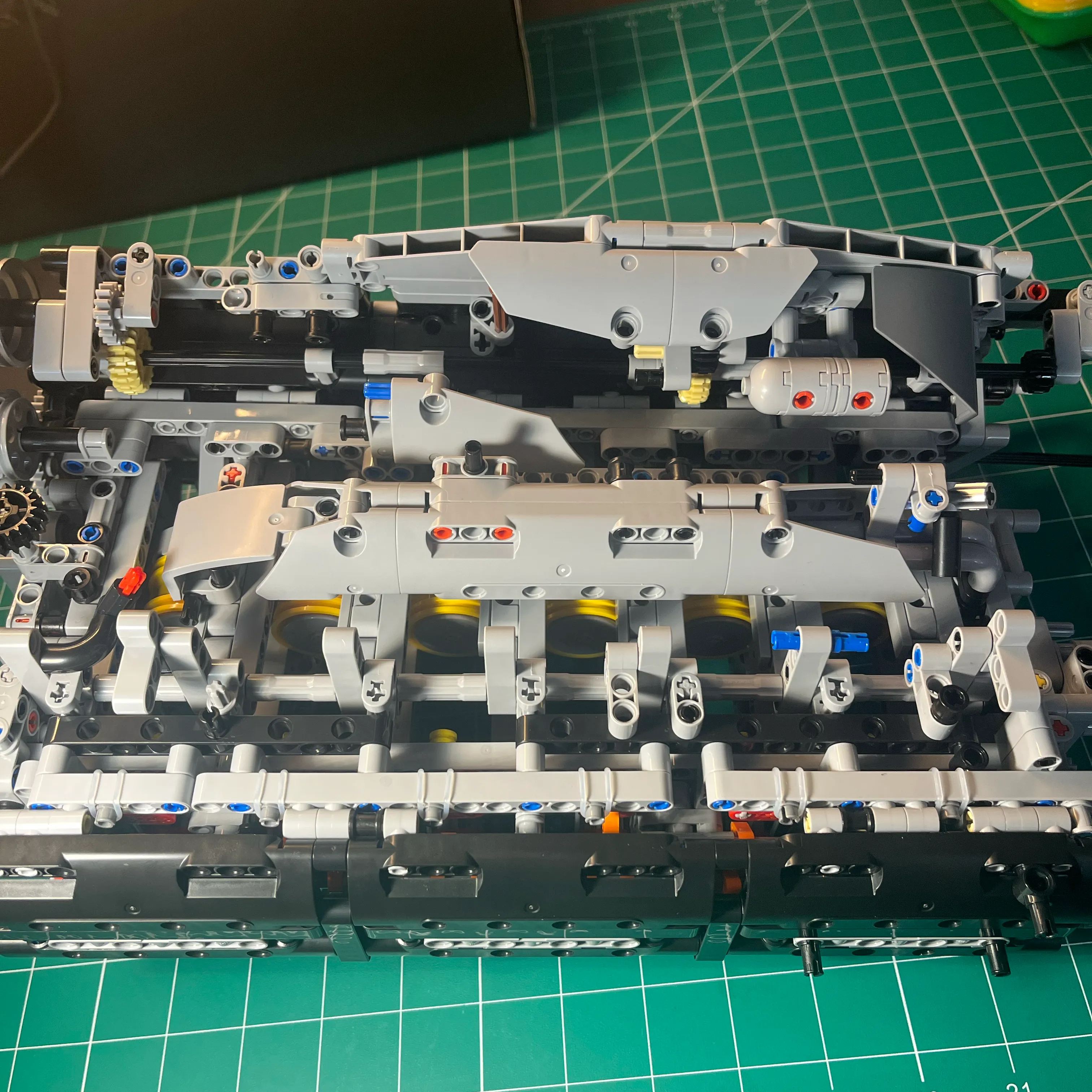
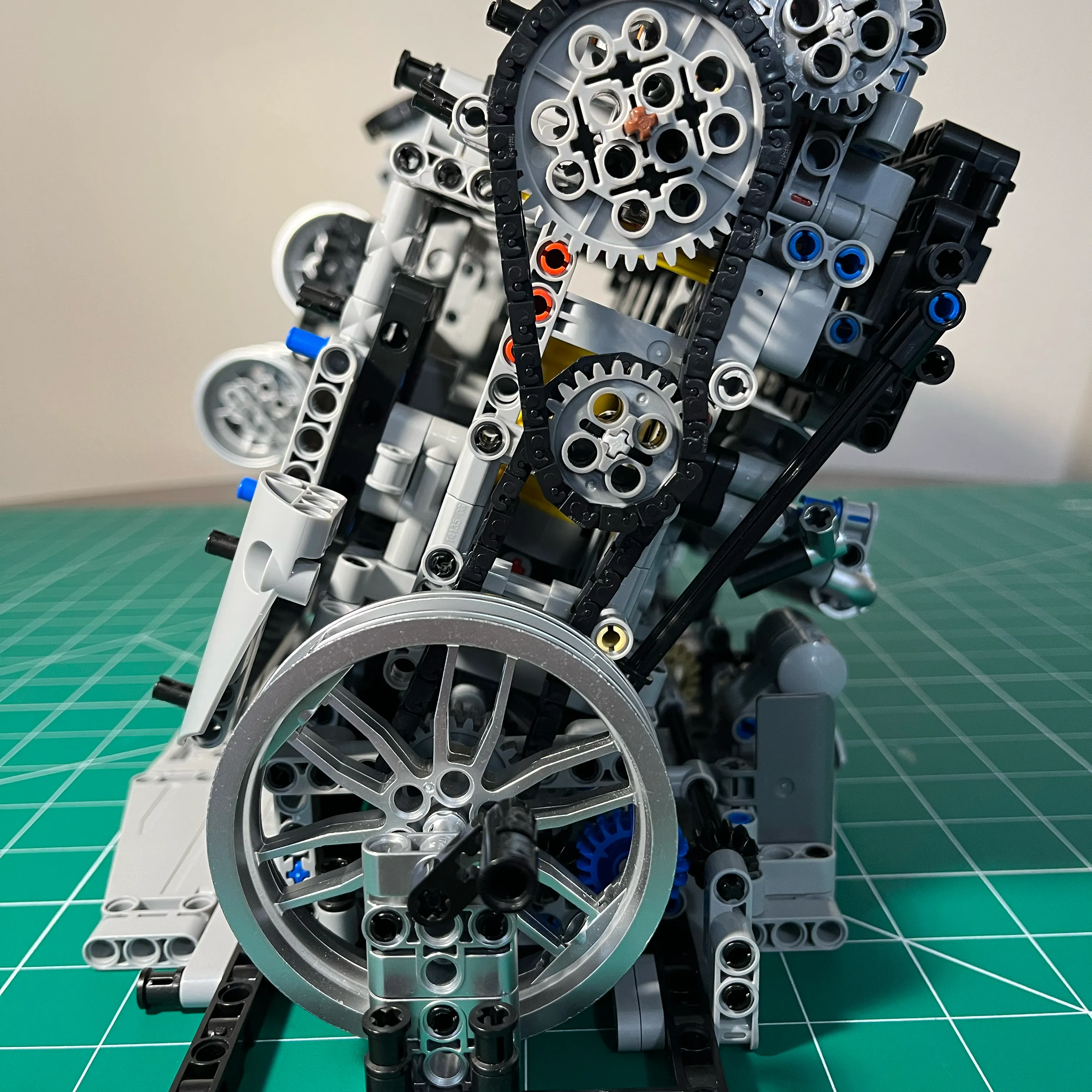
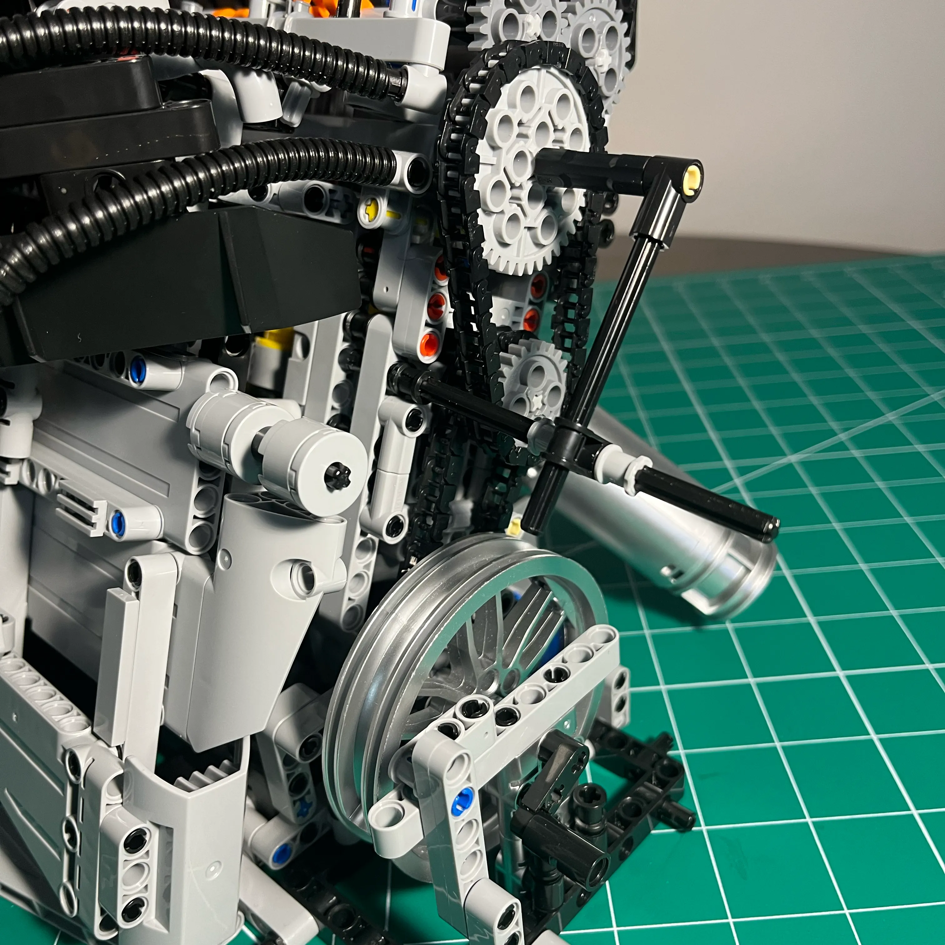
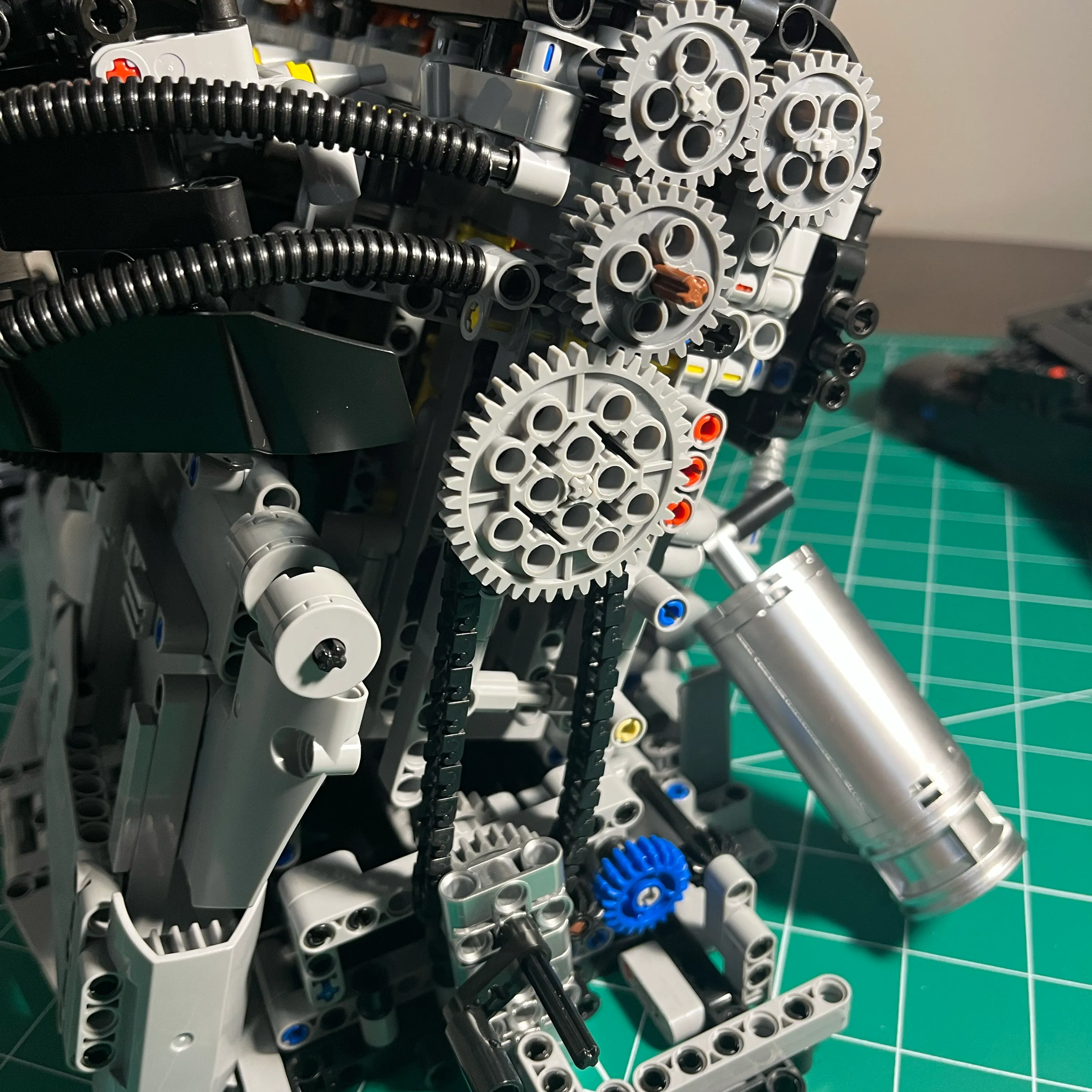
Cam Gears / Crank Configuration
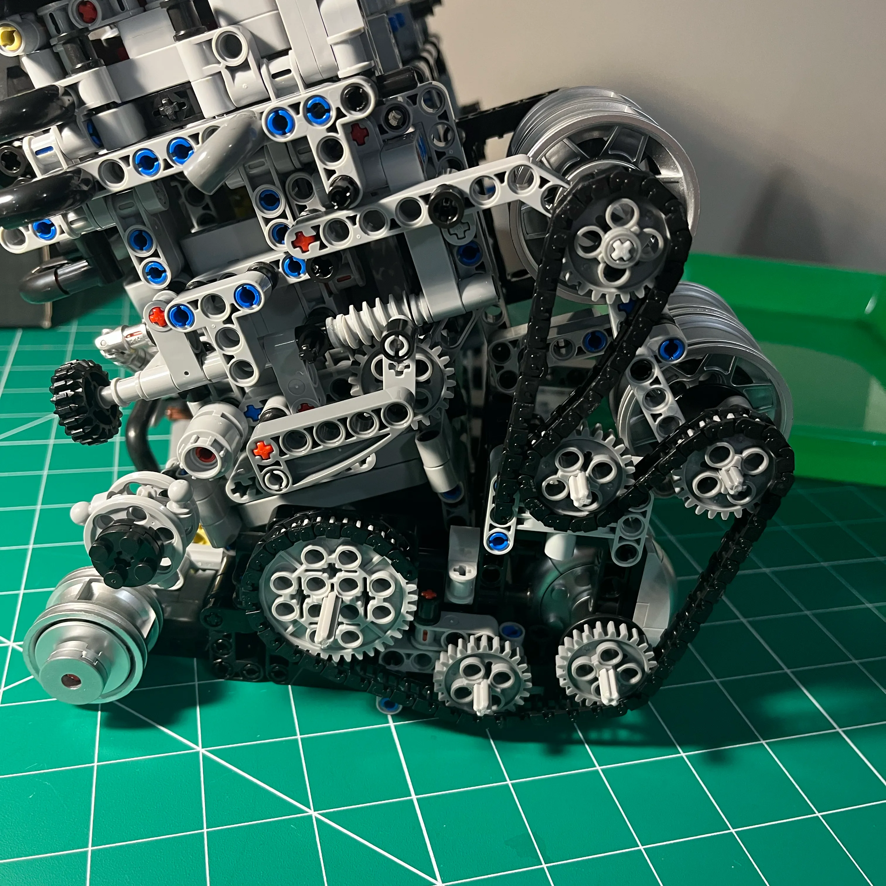
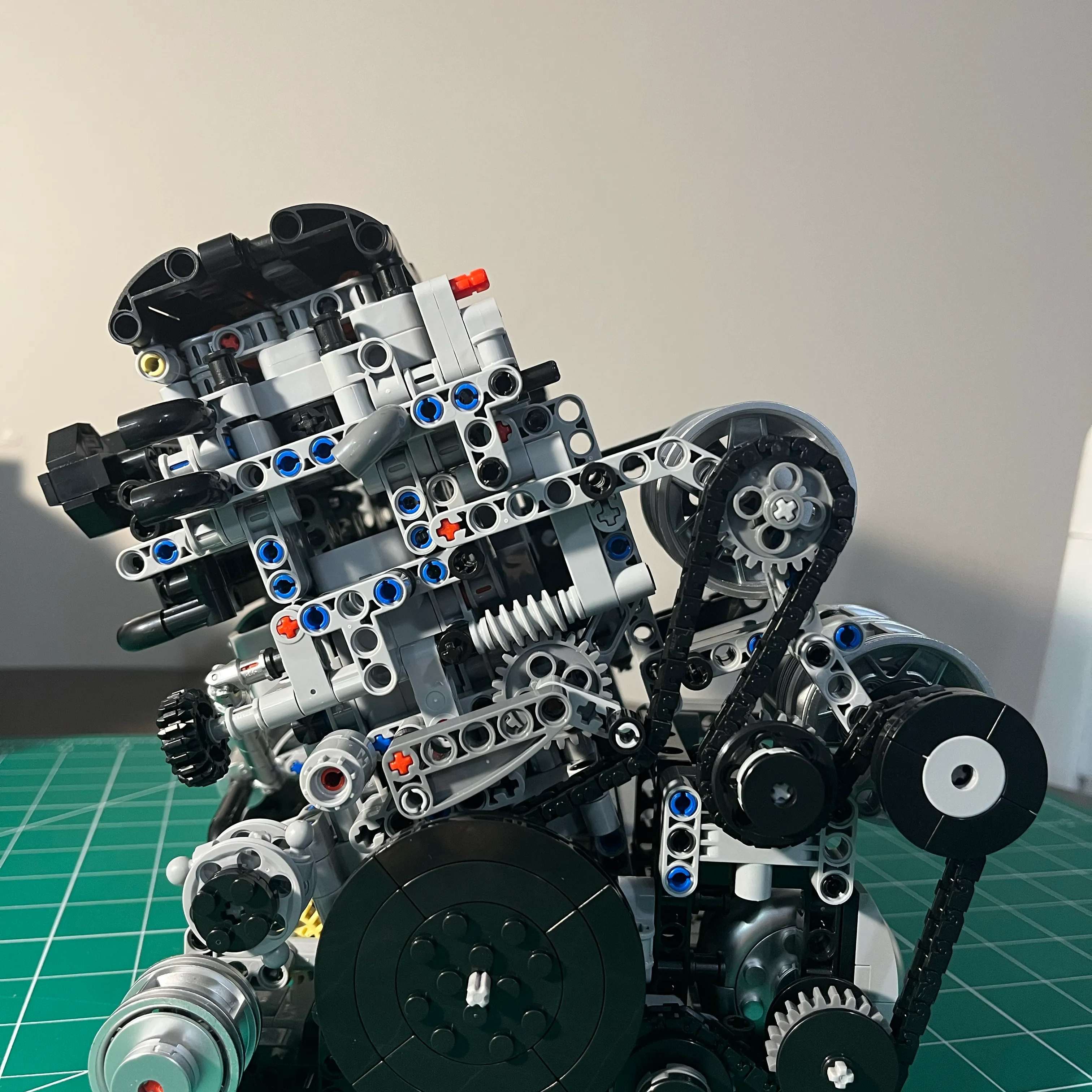
I had some trouble with the plastic gears used on the back of the engine, and the massive amounts of flex, and the use of a complex crank to cylinder head timing setup that has a gear on each of the 2 overhead cam shafts, 2 idler gears (one small one interlocked with the 2 cam gears), and one larger one on the outside of a plastic rod that is on the same rotating plastic rod as the small idler gear connected to the cam gears, and the large idler gear connected to the crank gear.
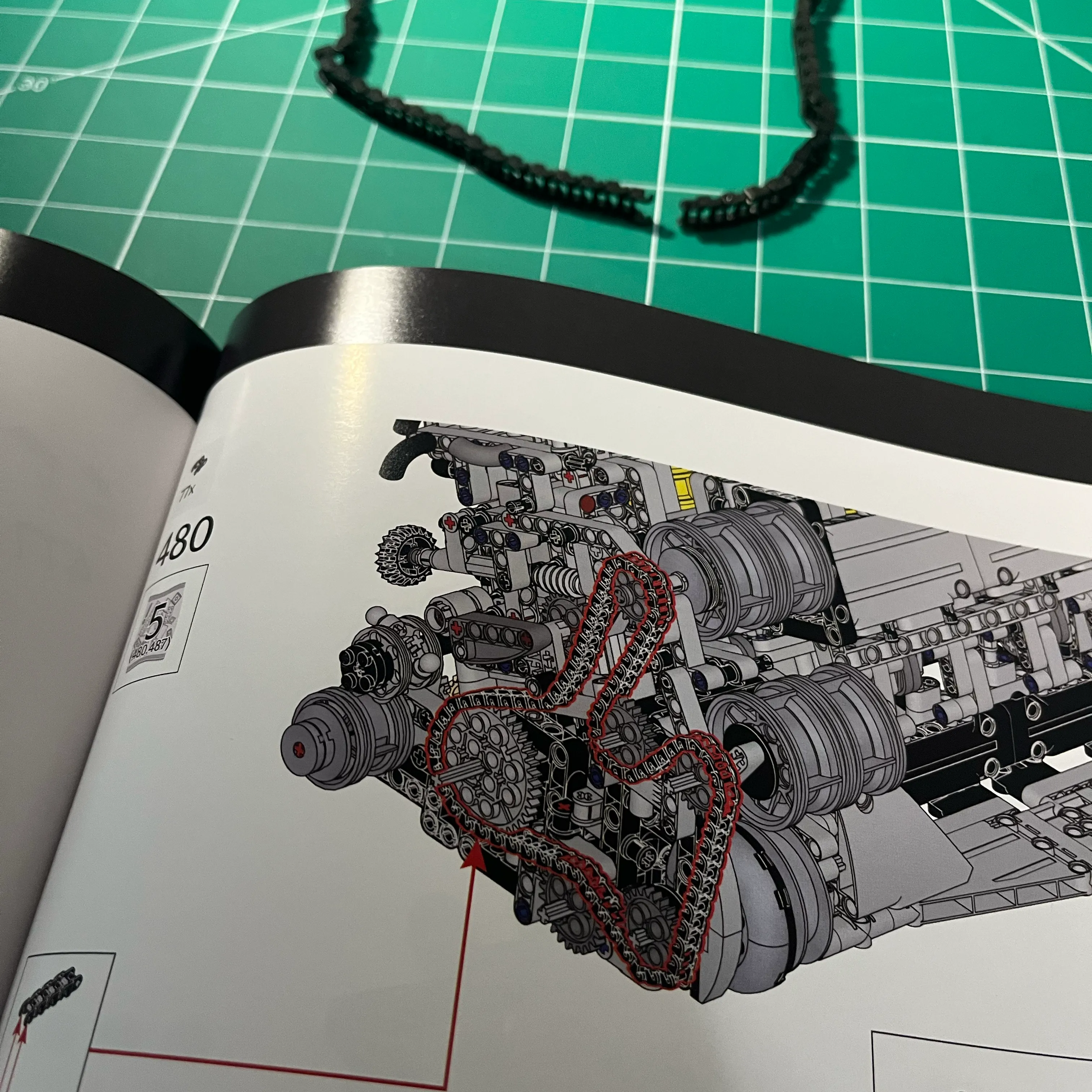
Here’s the cam gear / crank configuration, following the directions from the assembly manual.
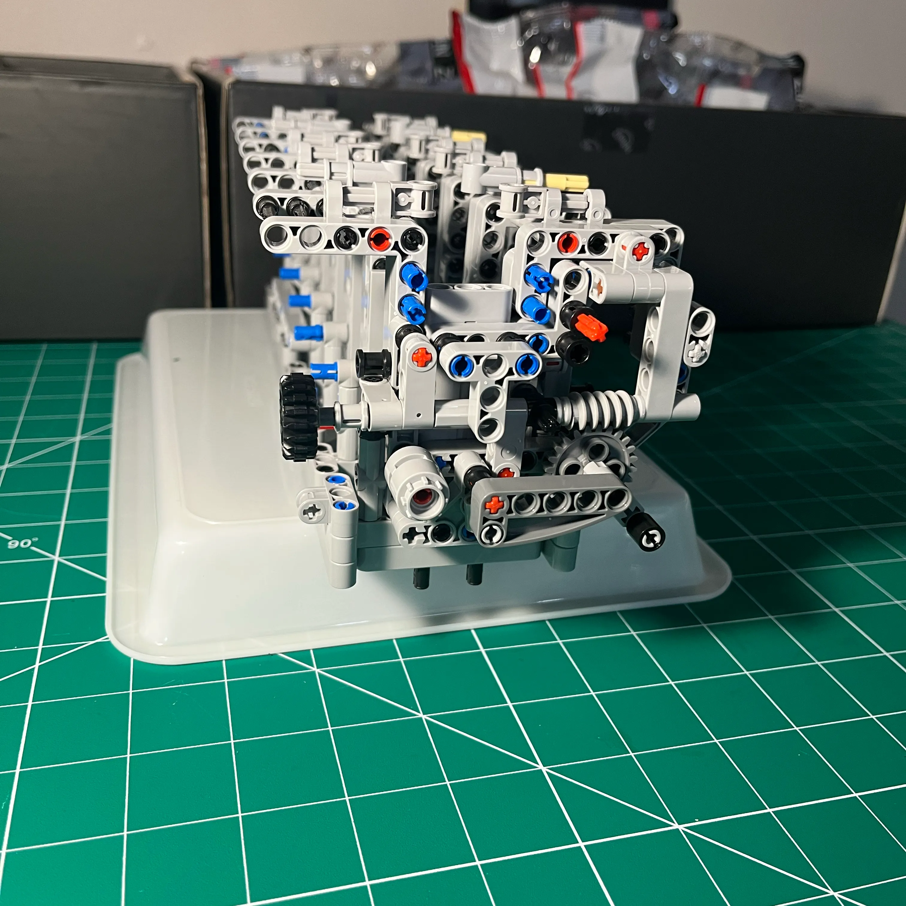
Cam Gear Redesign
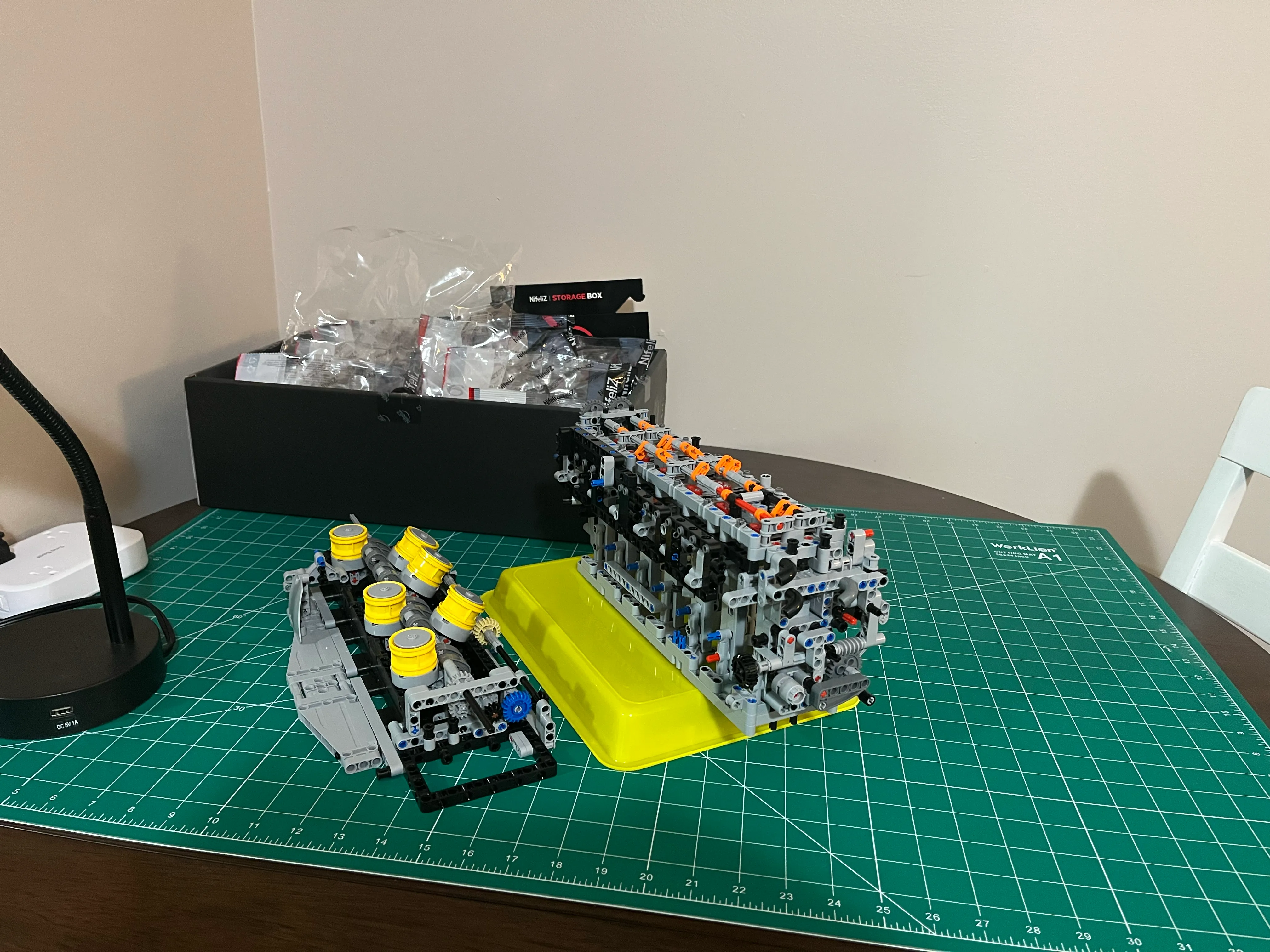
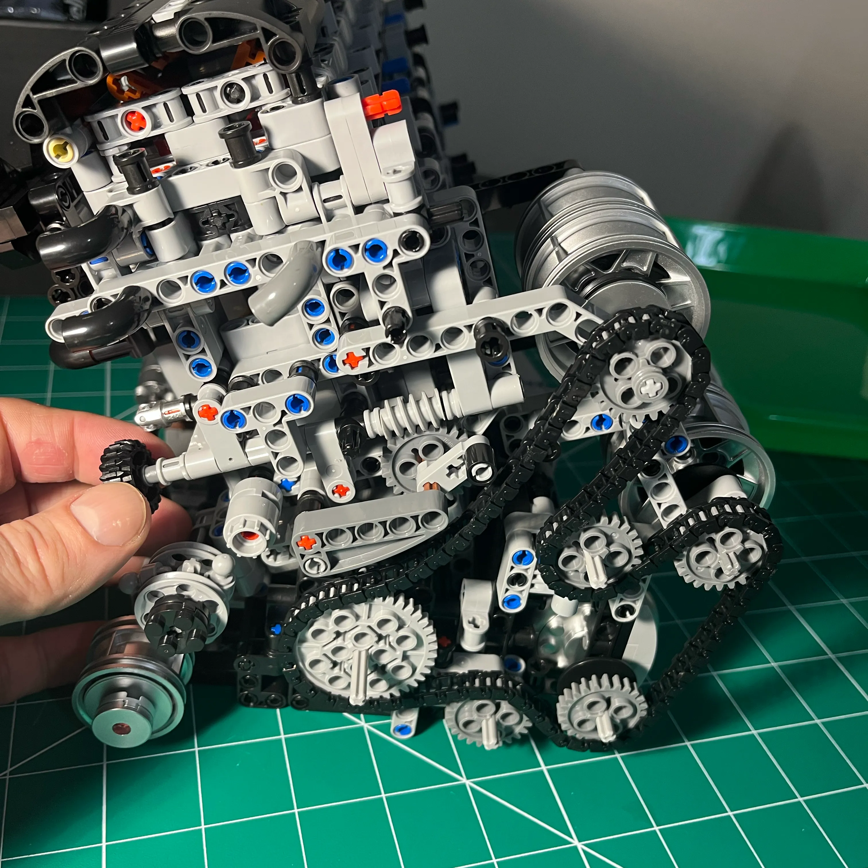
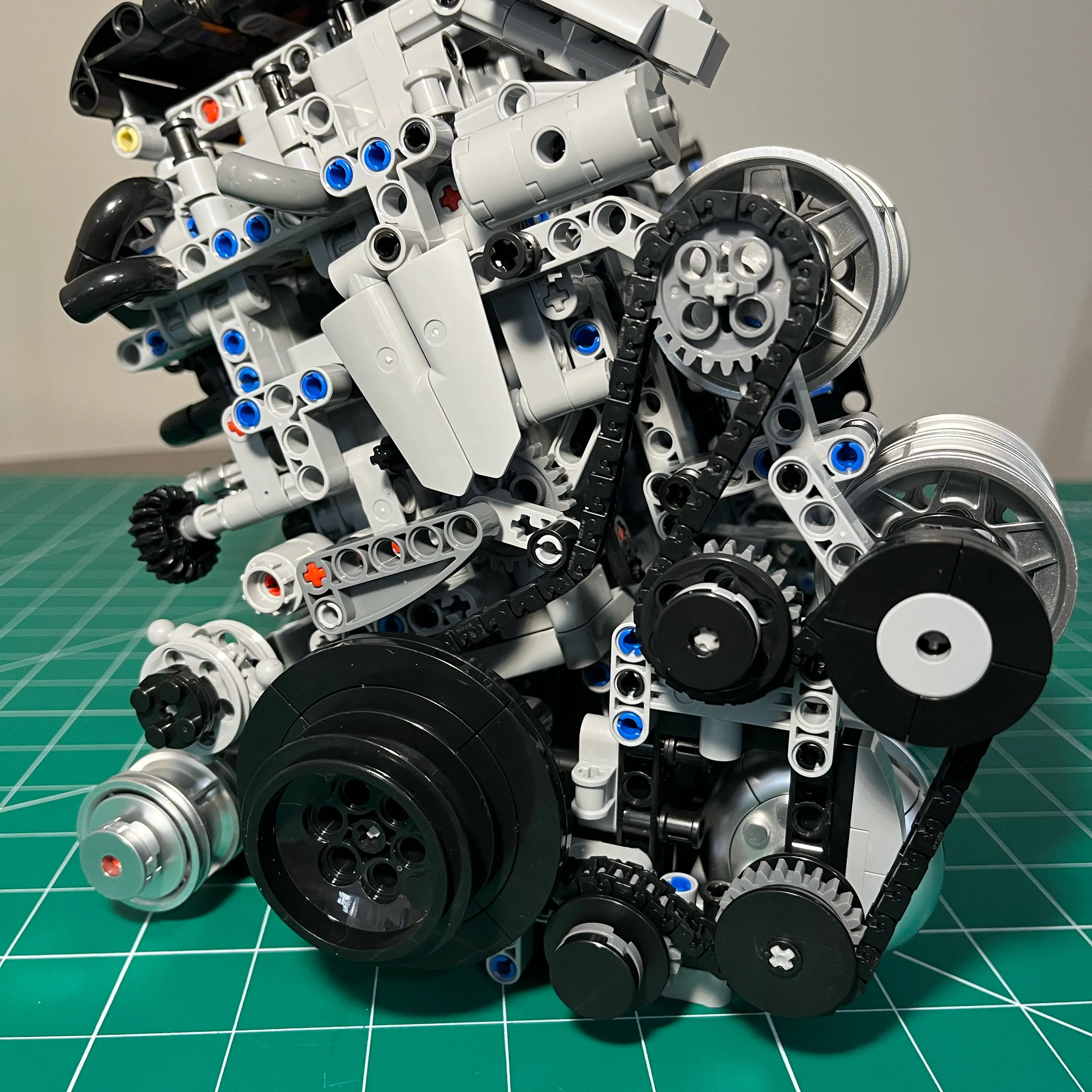
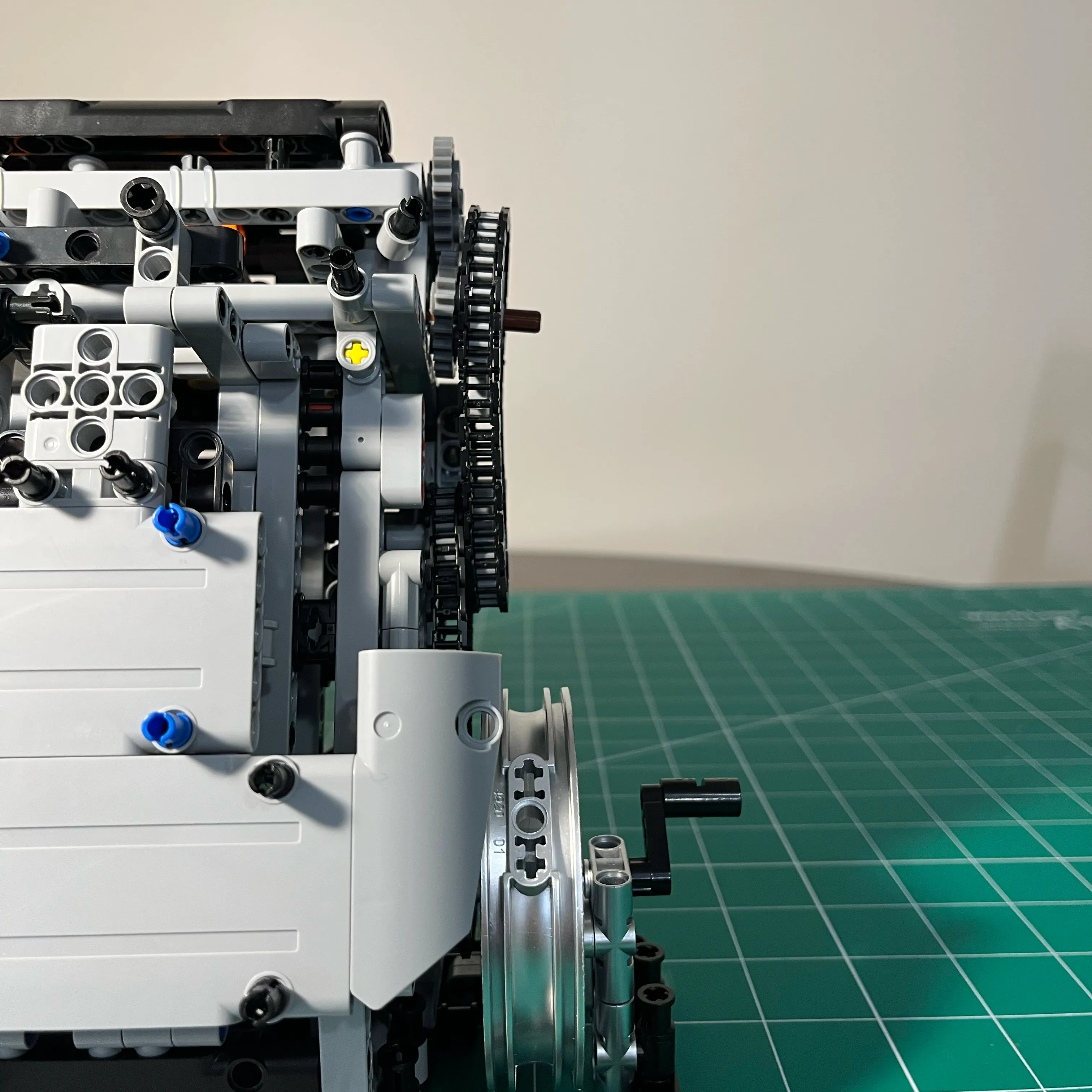
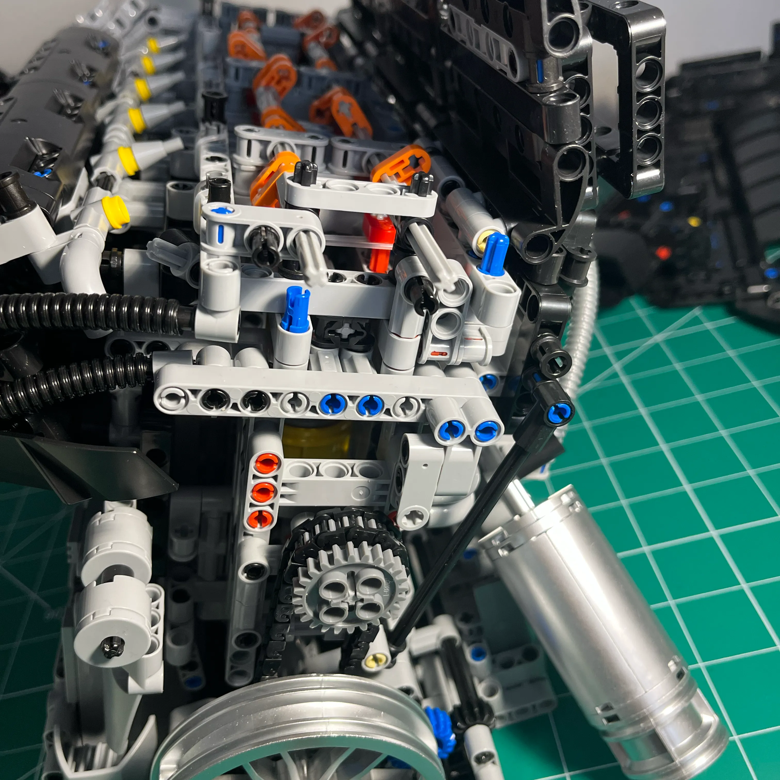
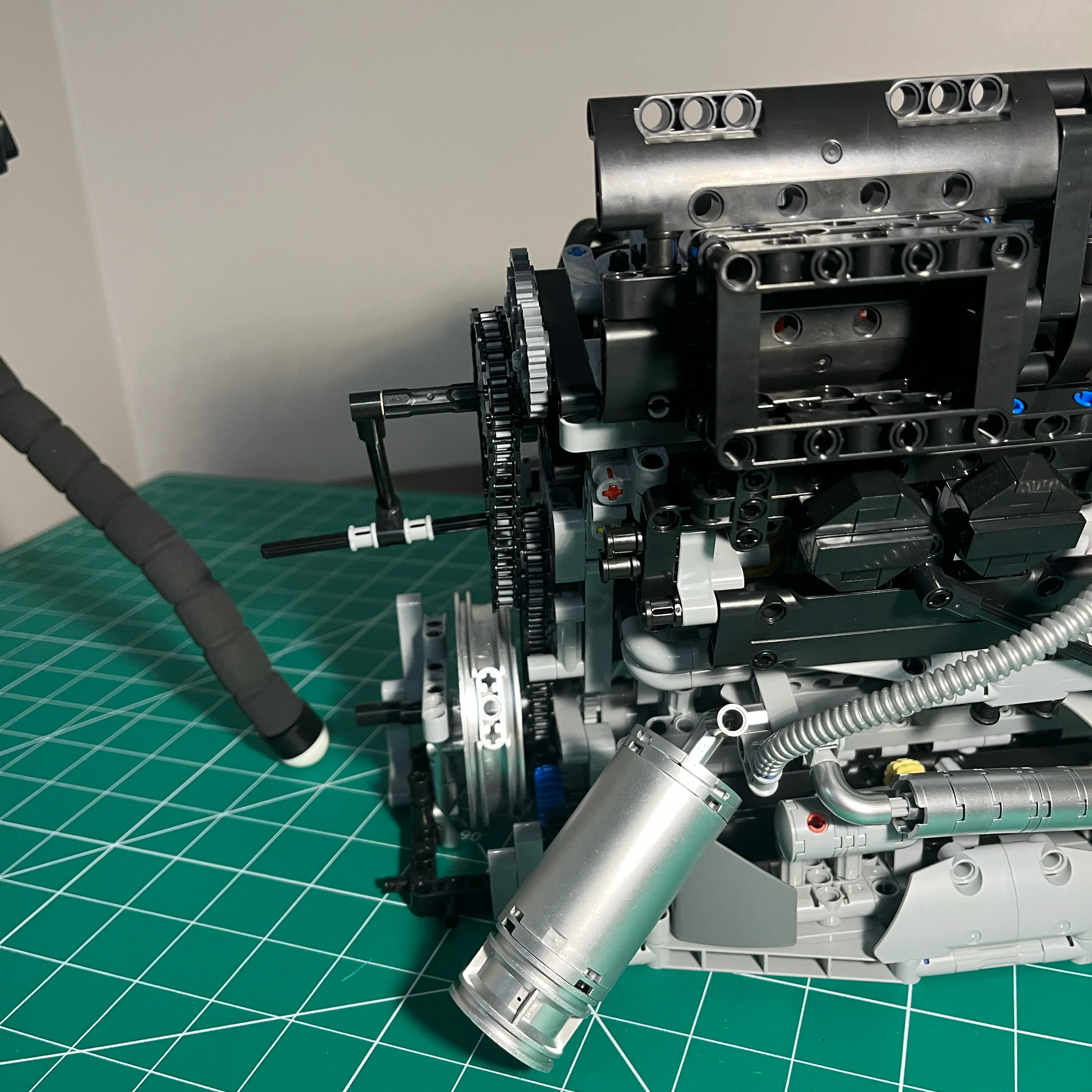
Due to the amount of friction in this plastic engine model, there is a surprising amount of torque required to start the engine spinning. Since the hand crank is on the rear of the engine on the crank, there is a lot of torque being applied to the 2 plastic chains. To get them to spin the engine, they need to be tight, otherwise they come off the gear. If you make them tight, that large gear on the central idler acts as a lever, and the tension on the chain pulls the idler gears down towards the crank, away from the cam gears, so the cams don’t turn. And that is happening with the crank and pistons spinning freely. the small crank gear has to turn over crank/pistons, turn over the idler and cam gears connected by plastic chains on a long plastic rod that has far too much play, as well as the accessories on the front of the engine including turbo, air compressor, alternator, connected to the front crank gear by a long chain. At least the front engine chain has an adjustable tensioner, and all gears are on short/sturdy connections to solid structure. The front of the engine is much better designed than the rear.
When I had the engine put together and somewhat functional, I started to think about how I could solve that rear gearing issue. If I put this engine on display, people are going to want to turn the engine over, including myself, and they are going to use the rear gear assembly to do it. It’s not really acceptable if someone tries to turn it over and runs into these issues.
The small hand crank that comes with the kit requires a lot of force to turn the engine over, which causes the crank to flex. The structure at the back of the engine is simply not sturdy enough to keep the rear gear assemblies in alignment, and the plastic chains are not designed to handle gears with that much flex, so the chains come apart.
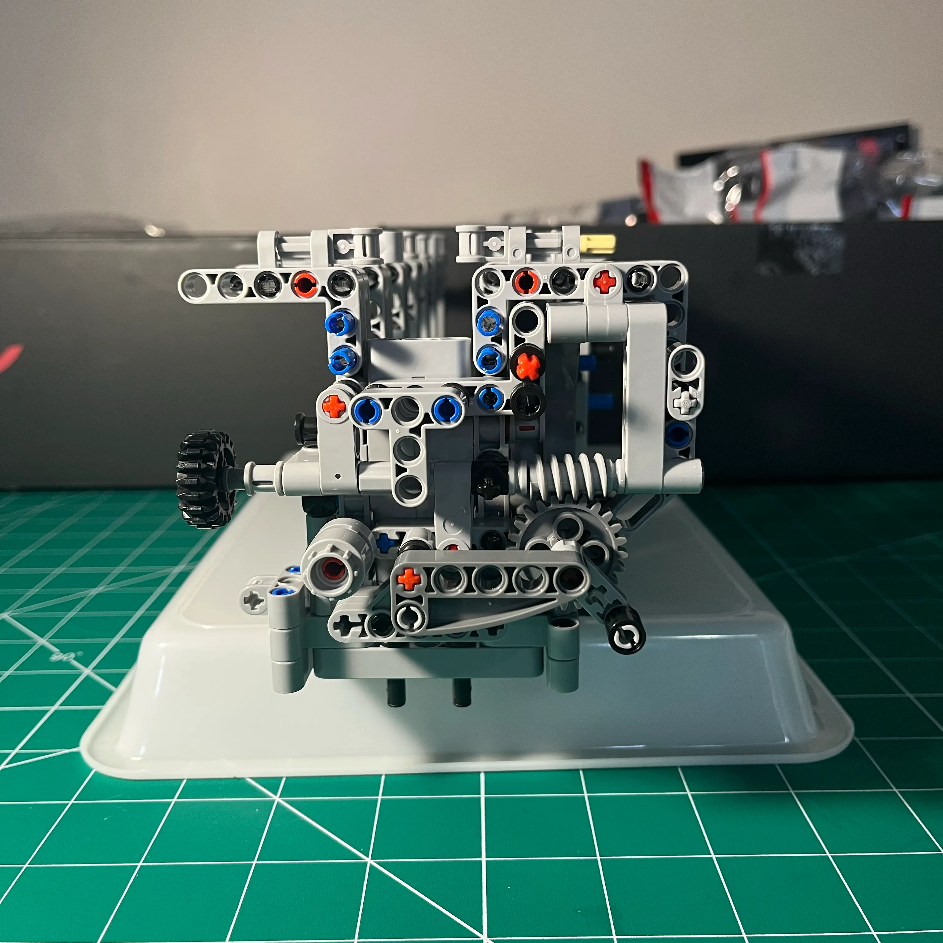
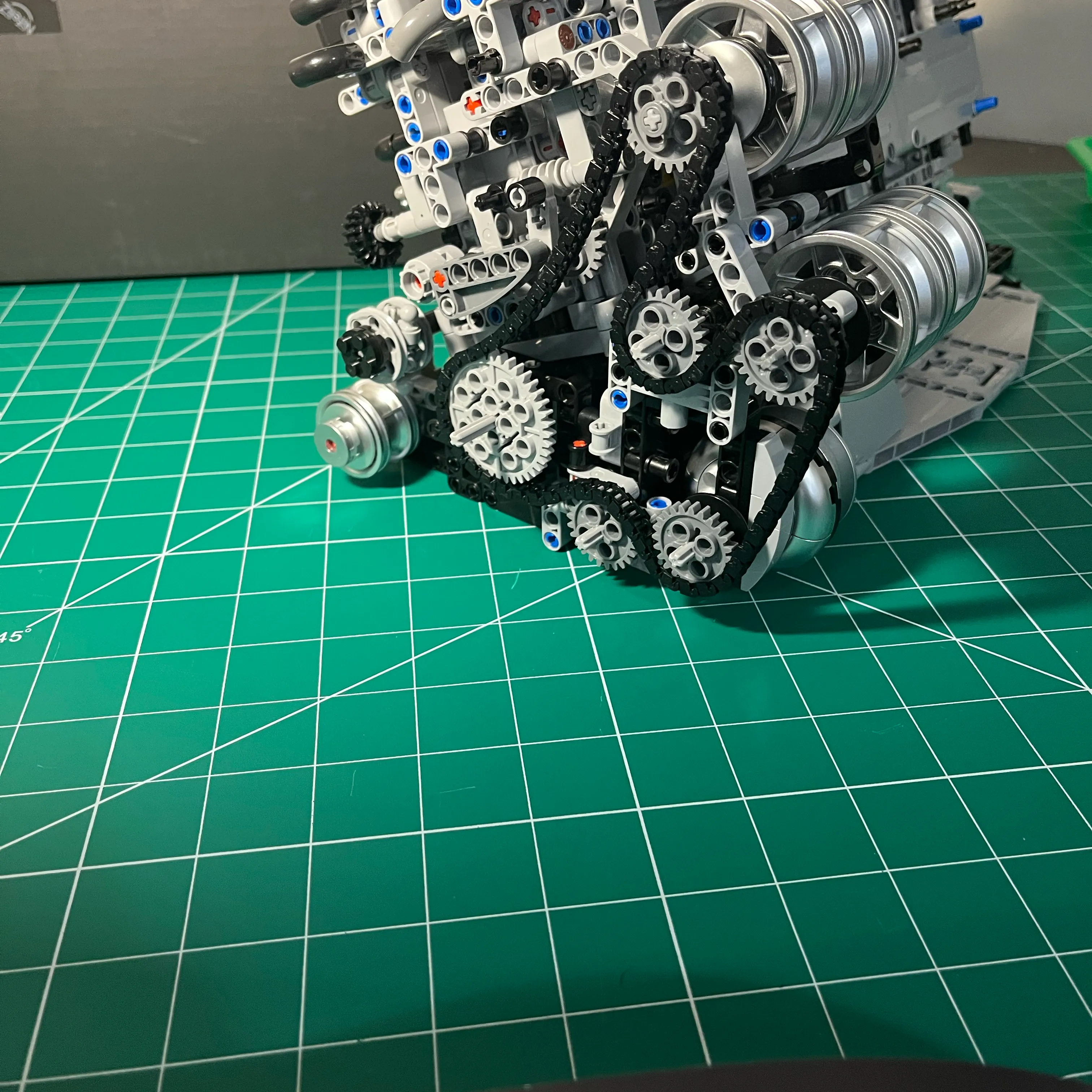
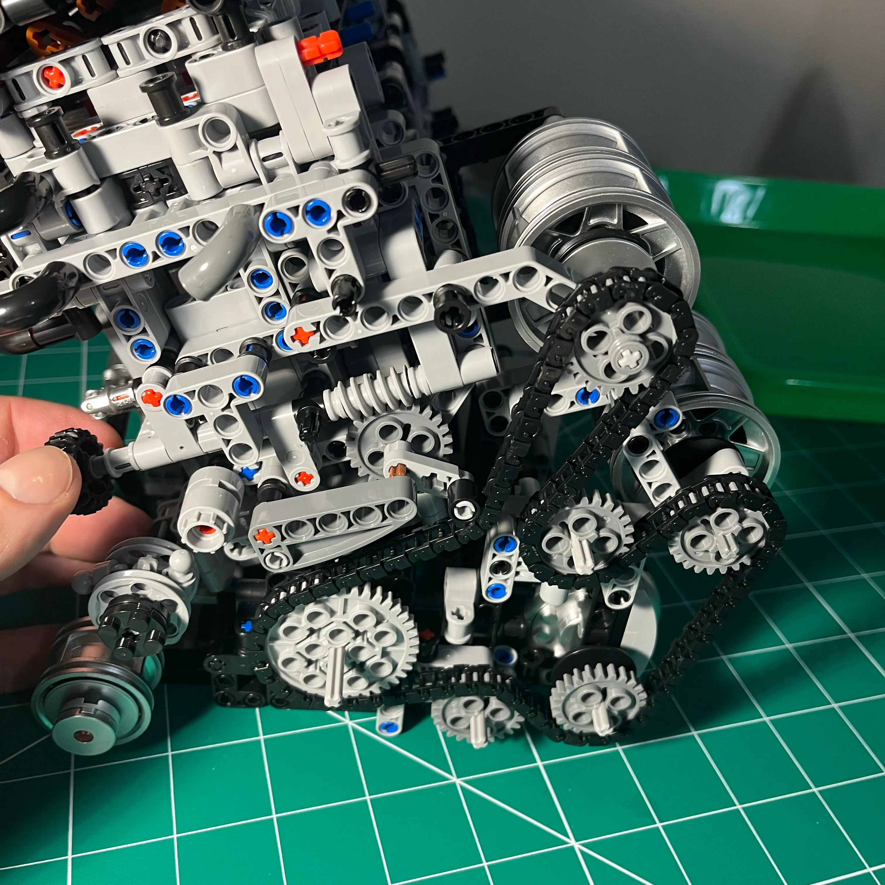
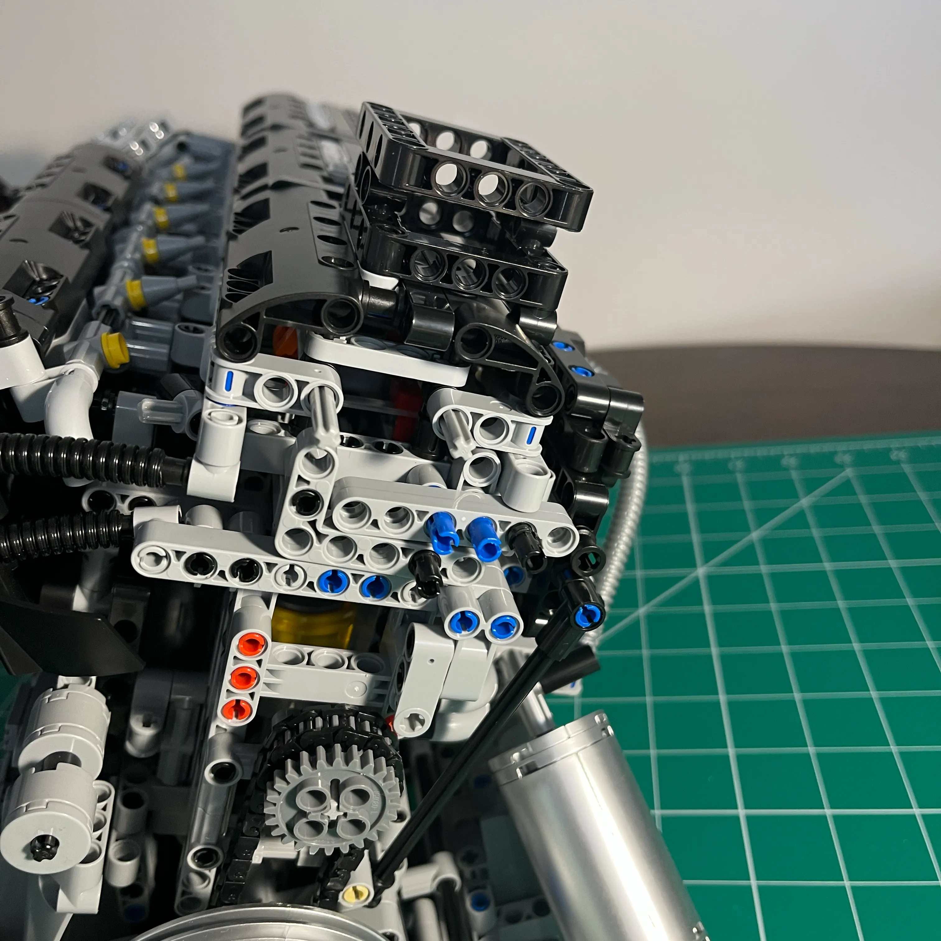
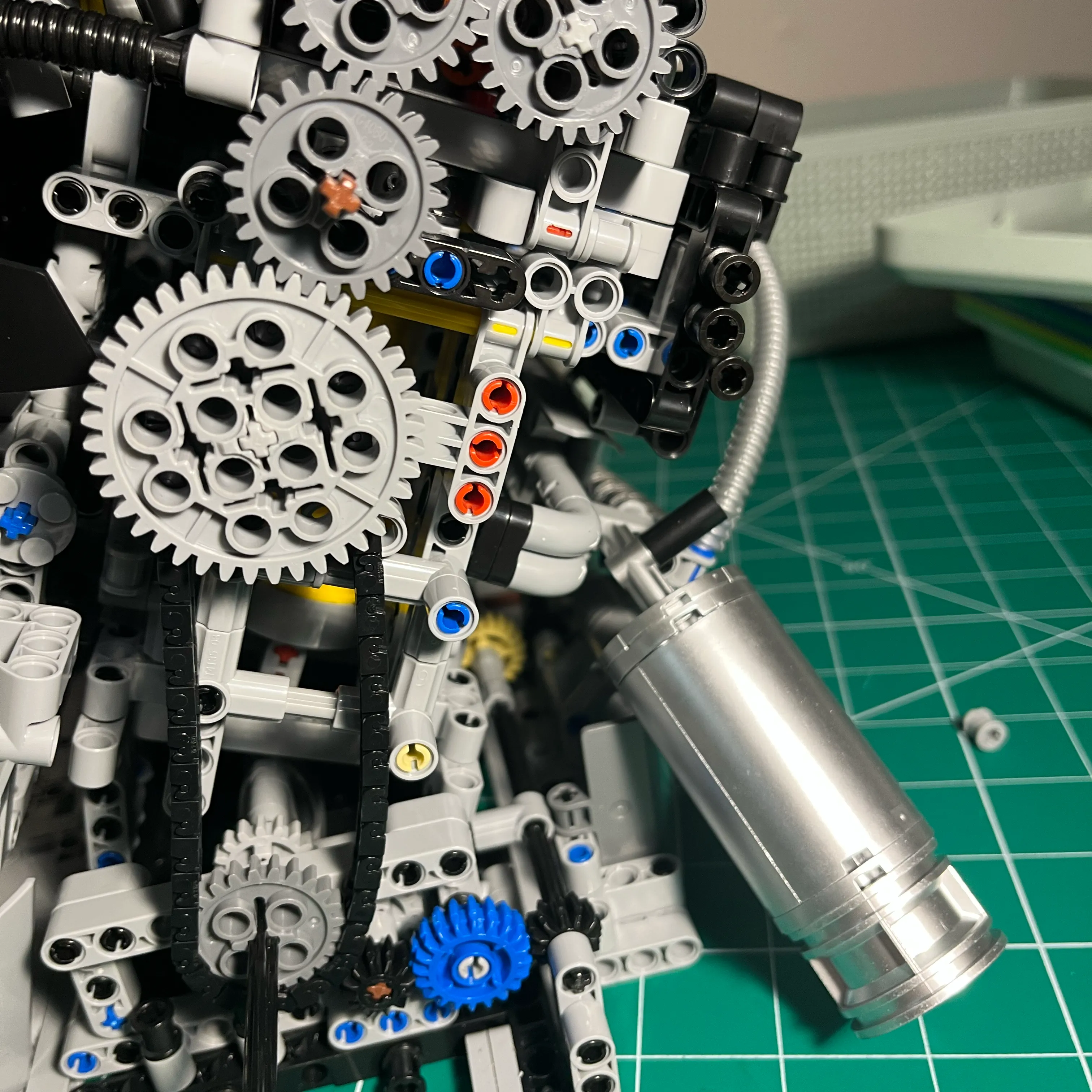
I solved that problem by redesigning the back of the engine to eliminate the upper chain, replacing the upper chain with a direct gear drive. I saw that the large gear on the idler pin was acting as a lever, so I thought that I could eliminate that by moving the larger gear directly on the block tied to structure, and pushing up against the small idler gear that’s in the same location. The flexibility of that long pin becomes moot since all the gears are now, by design, in perfect alignment.
I changed the design again after this. My design has 2 small gears on the cam intermeshed, below an small idler gear is intermeshed with one of the cam gears (so it drives both cams), and on that same pin another small gear. Below the 2 doubled up idler gears, the large gear is intermeshed with the outer idler gear above. Since the large gear is mounted on as short of a pin and as sturdy as possible, it keeps the gears in contact with the cam. On the inside of the pin where the large gear is a small gear. Both these gears are on the same pin, and are structurally sound. Since I removed one chain, the chain from the crank to the first idler pulley is now too short. But I have the other chain, so I made the chain attached to the crank longer.
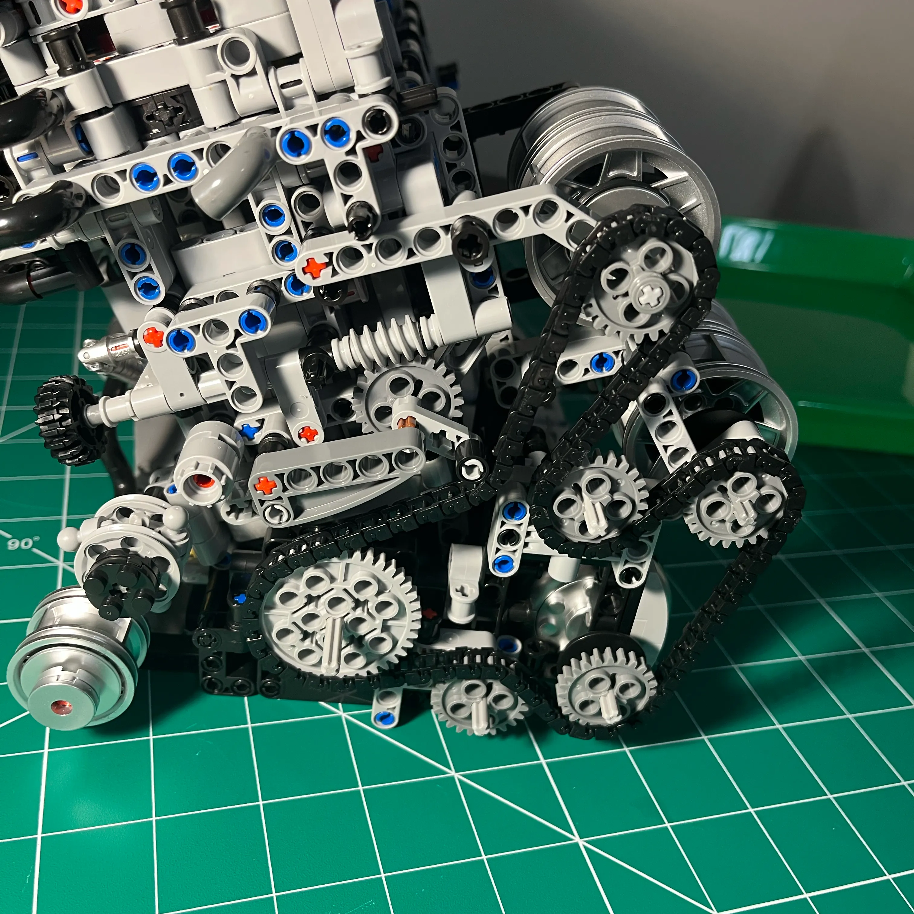
It works much better now! One chain connecting 2 small gears, as close to the engine block as I could get to reduce leverage action on the gears. The small idler gear that is connected to the crank by the chain has the large gear on the same pin. This larger gear is intermeshed with another small idler gear that’s on a double idler pin with another small gear on the inside that’s intermeshed with the 2 cam gears. This design requires fewer parts overall, and actually works.
While 2 chains looks cooler, I prefer it to actually work and be reliable. I have ordered some Technic bricks from Amazon which I want to explore making the rear of the engine better. There weren’t enough gears included with the NifeilZ kit to eliminate the chain altogether. I am going to try to make the crank and the cams connected with direct gear drives, making the rear completely bulletproof. That lets me use gear ratios to make the engine turn over much smoother.
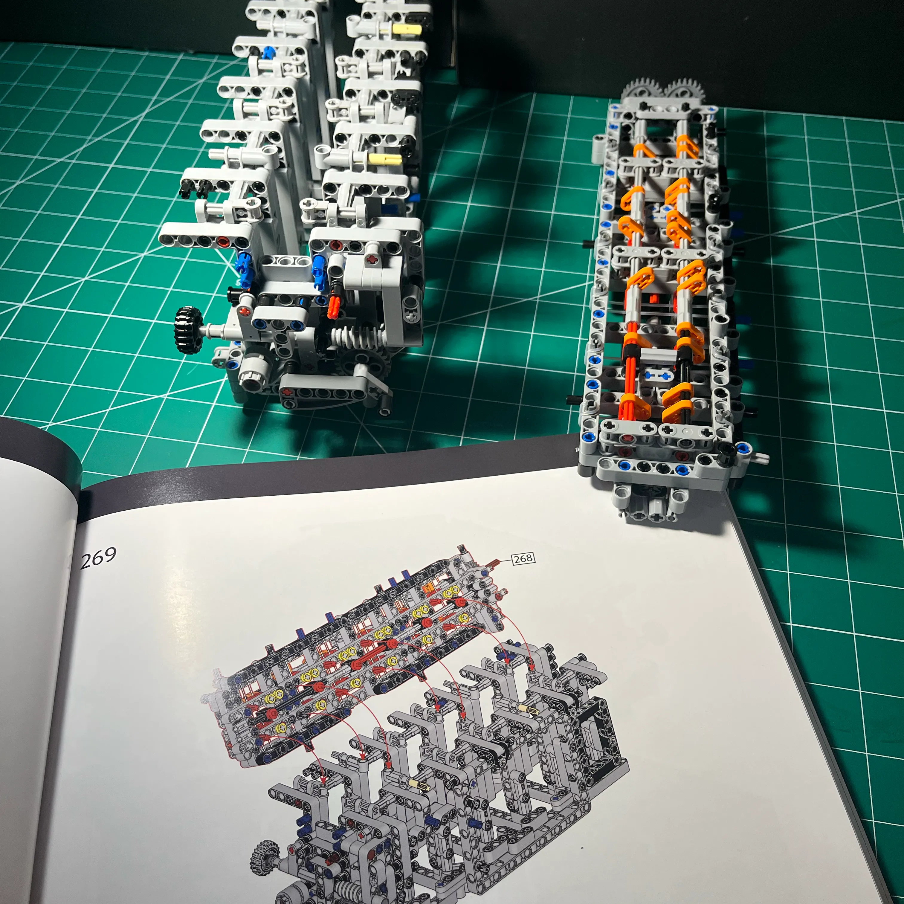
Removed the 2 cam gears and the idler gears to assess the design
Used the brace from the coil pack frame as an exo-skeleton
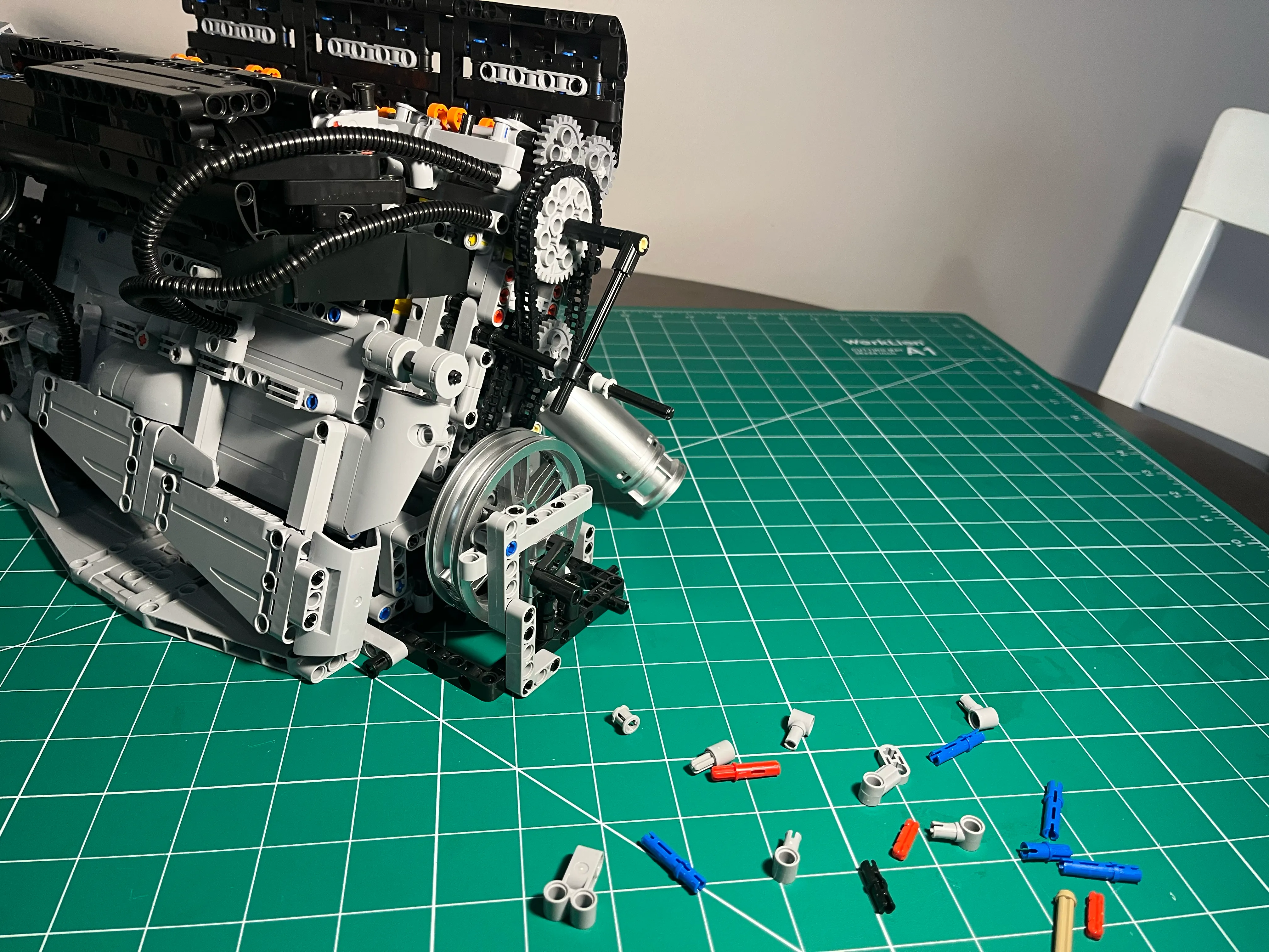
It did seem to help but it wasn’t practical. After thinking about it, I decided to eliminate the upper chain and replace it with a direct gear drive.
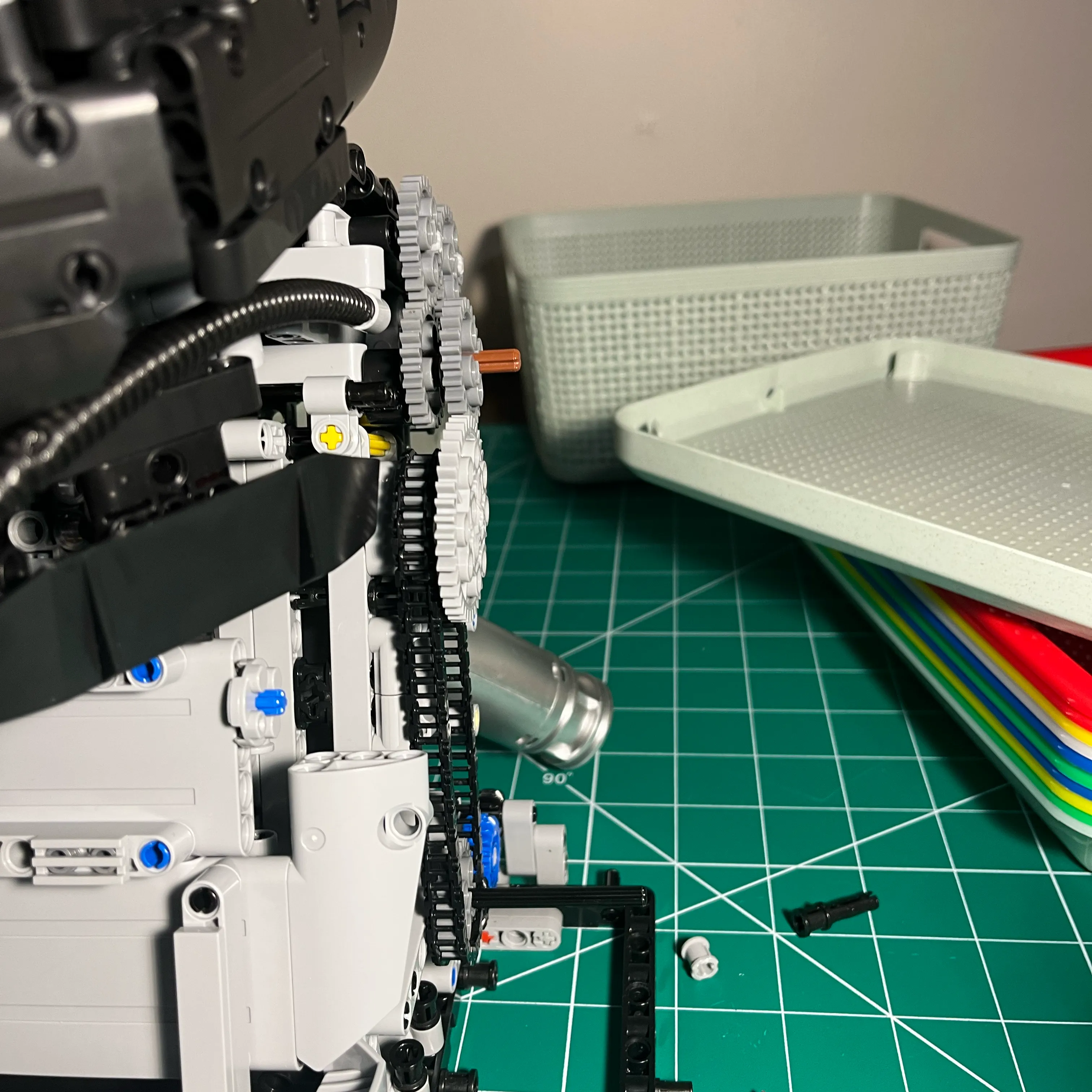
Here’s the new cam gear design in action.
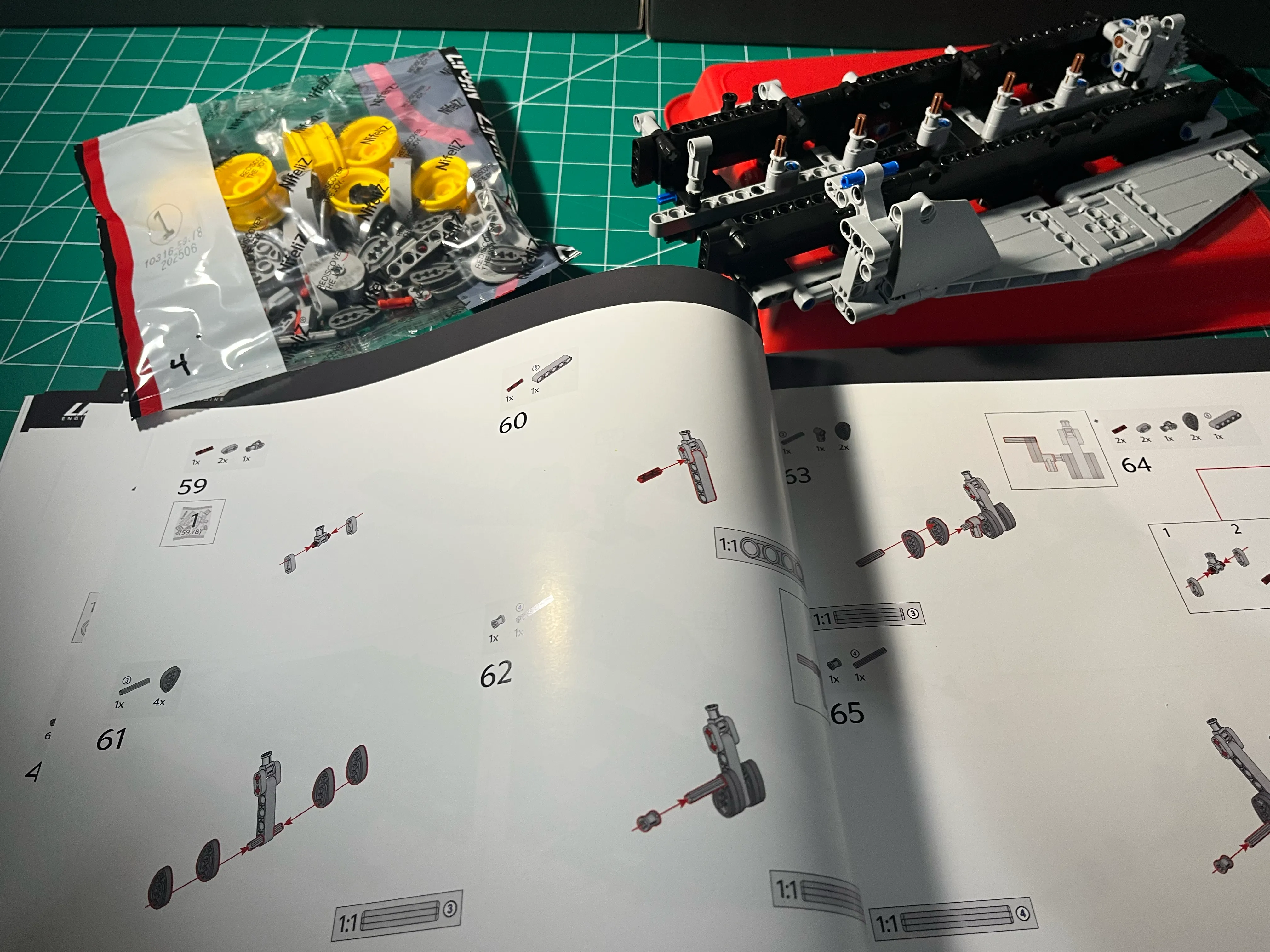
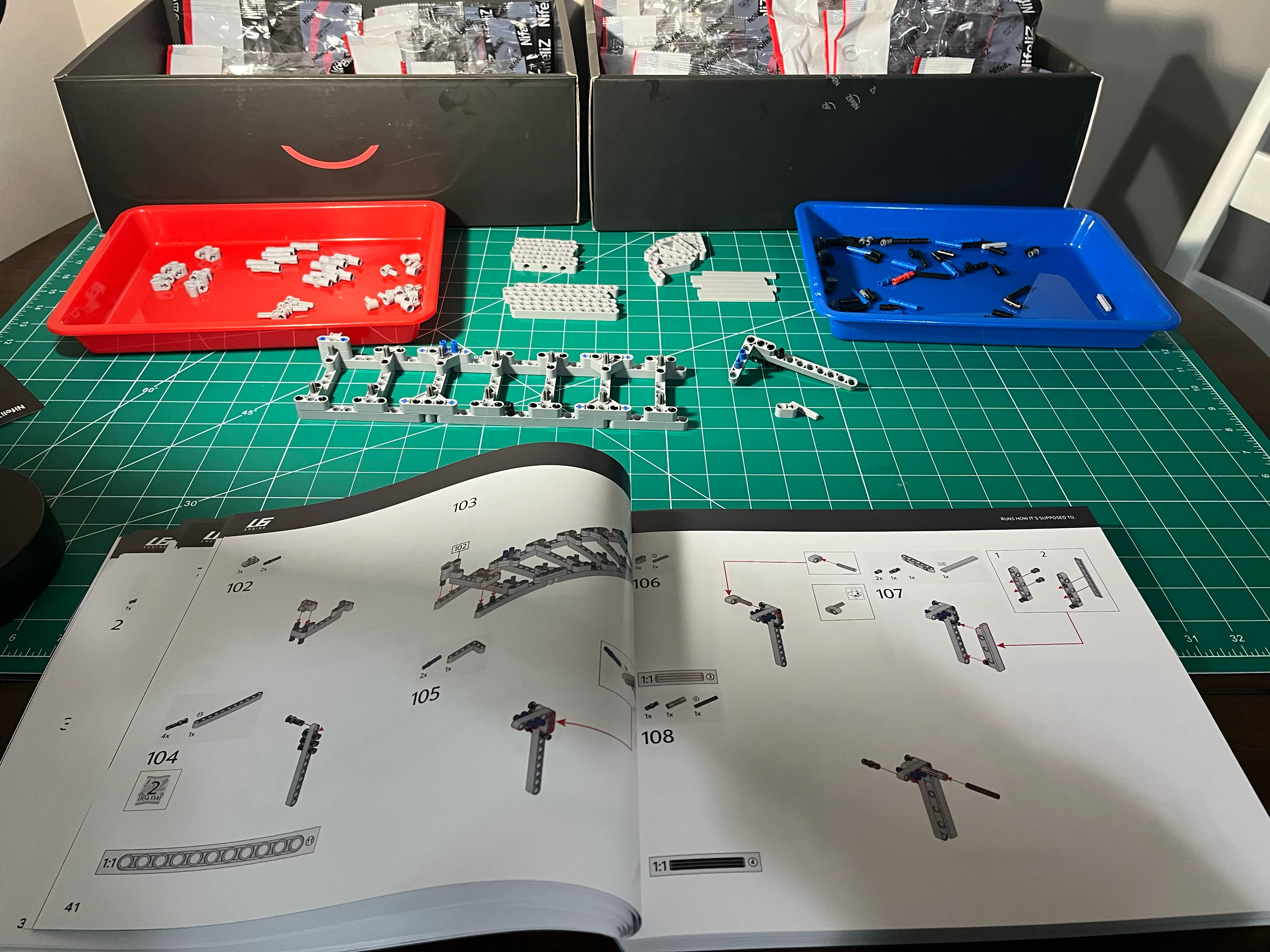
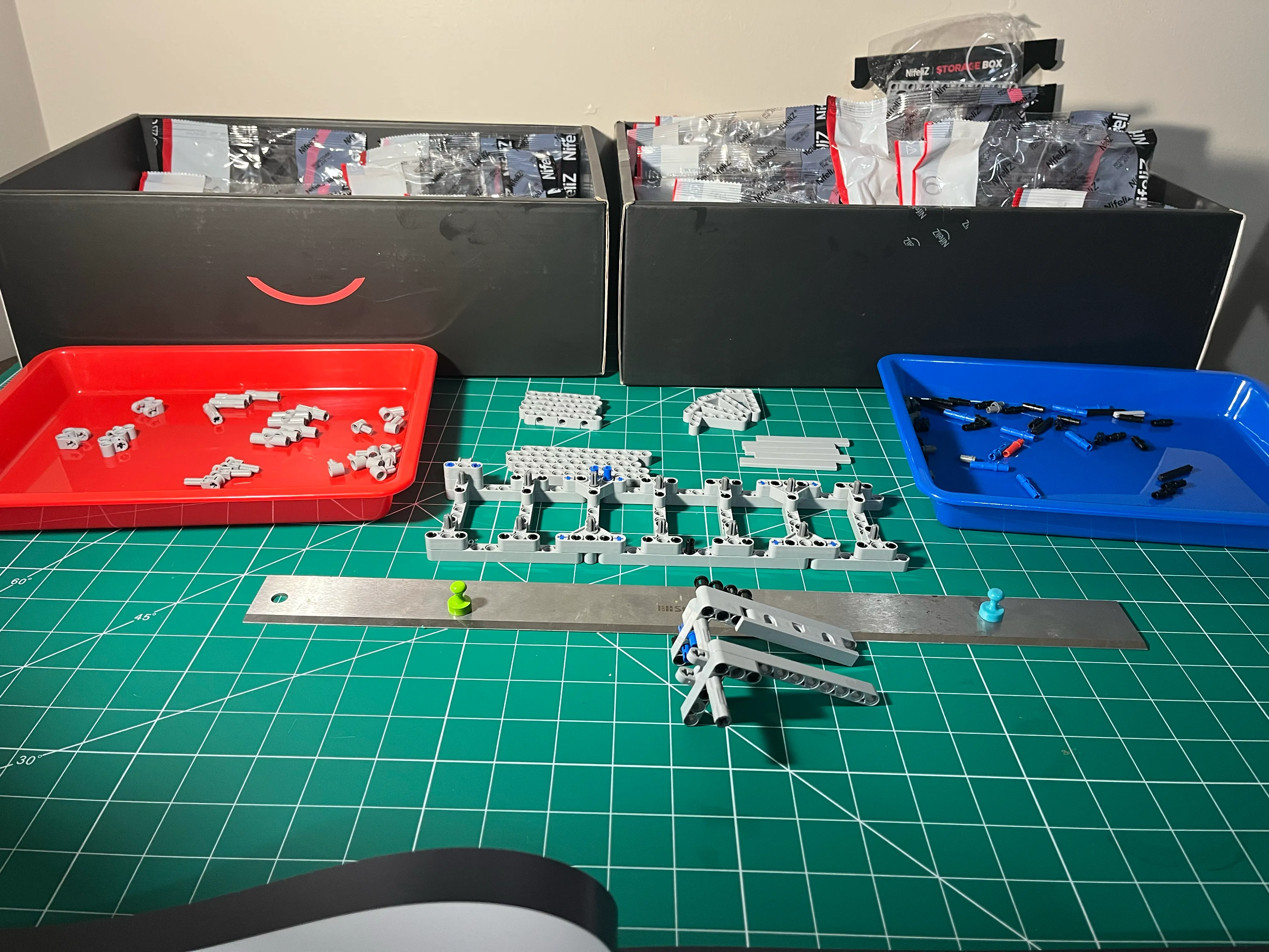
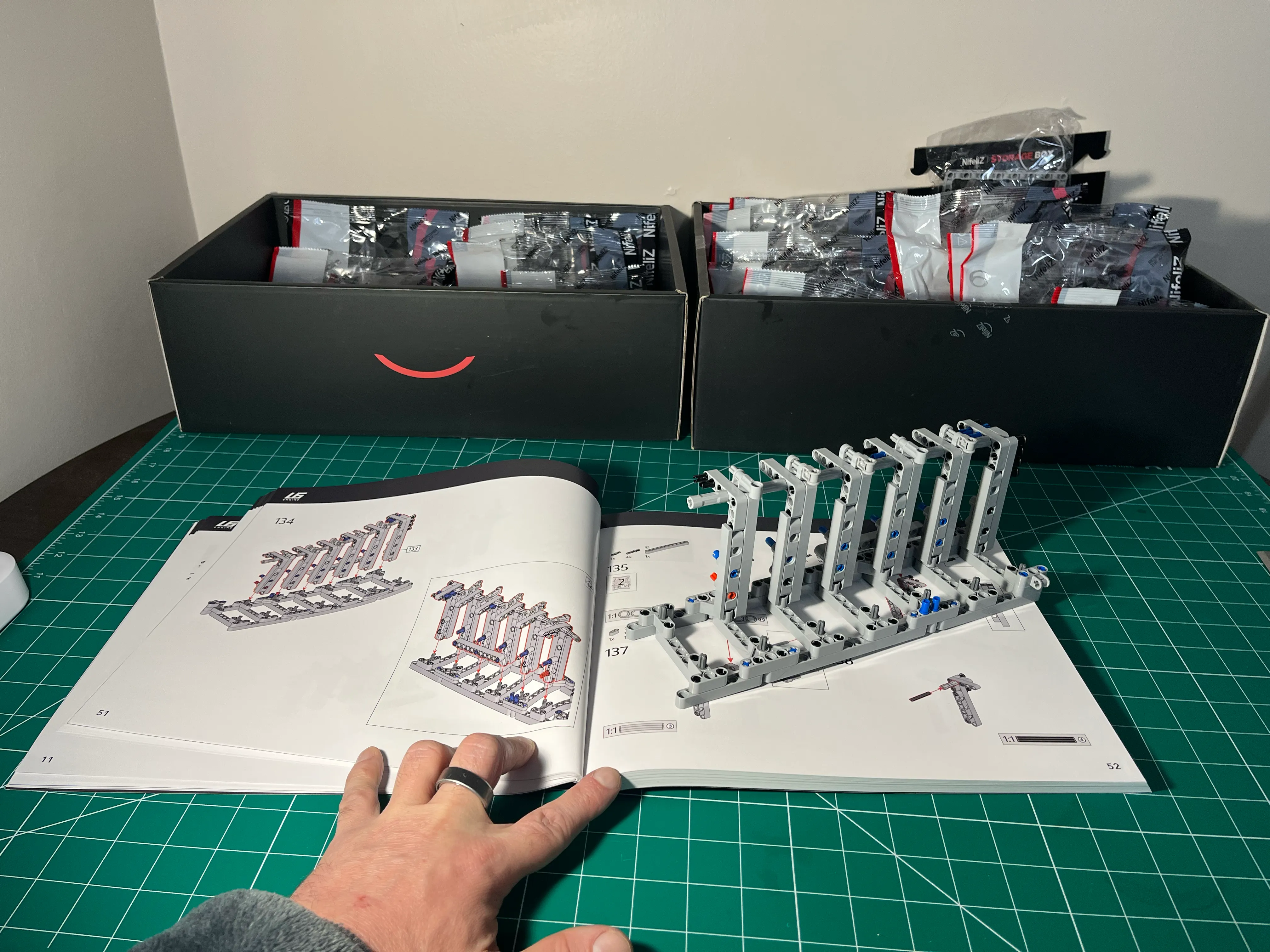
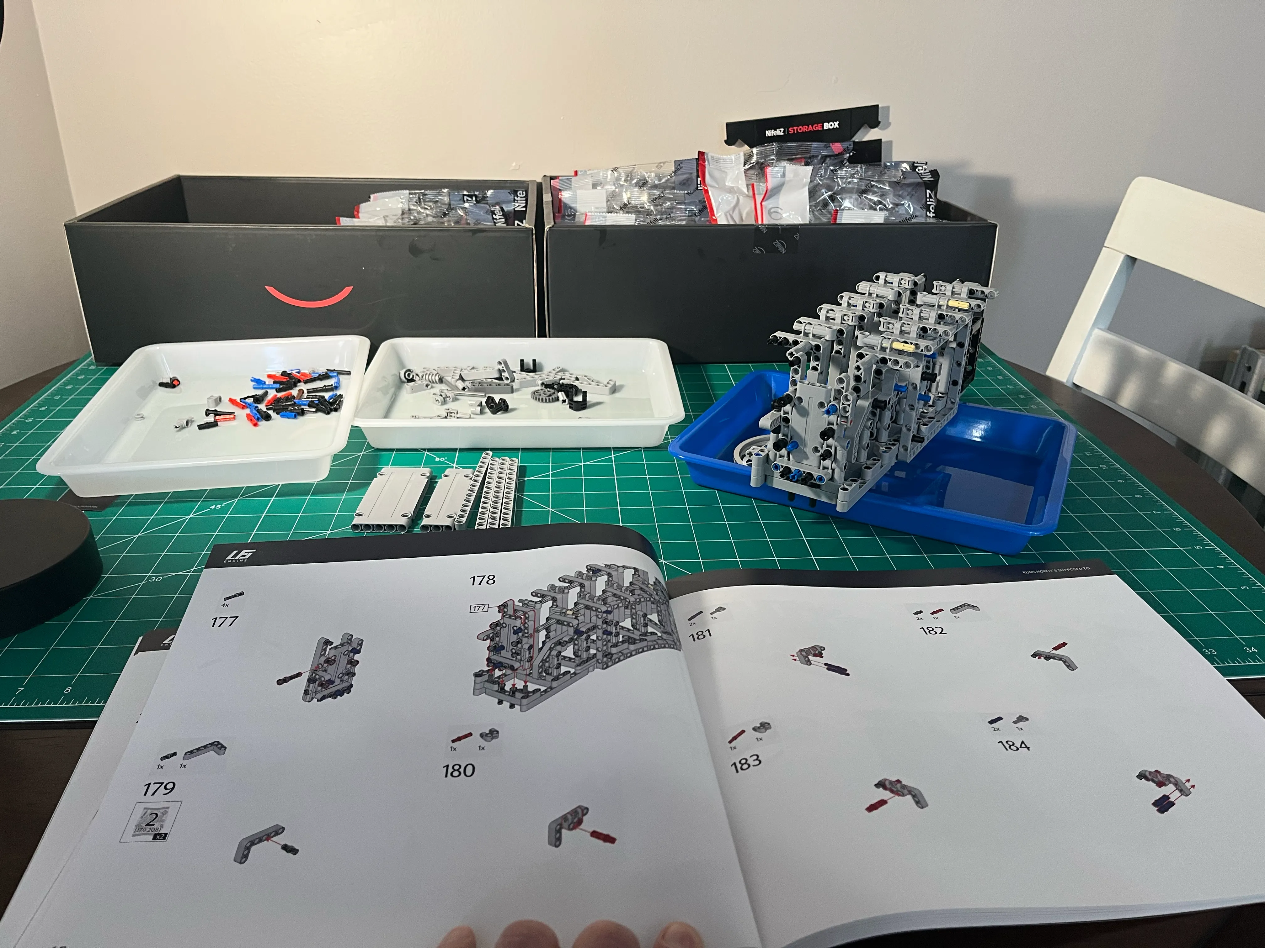
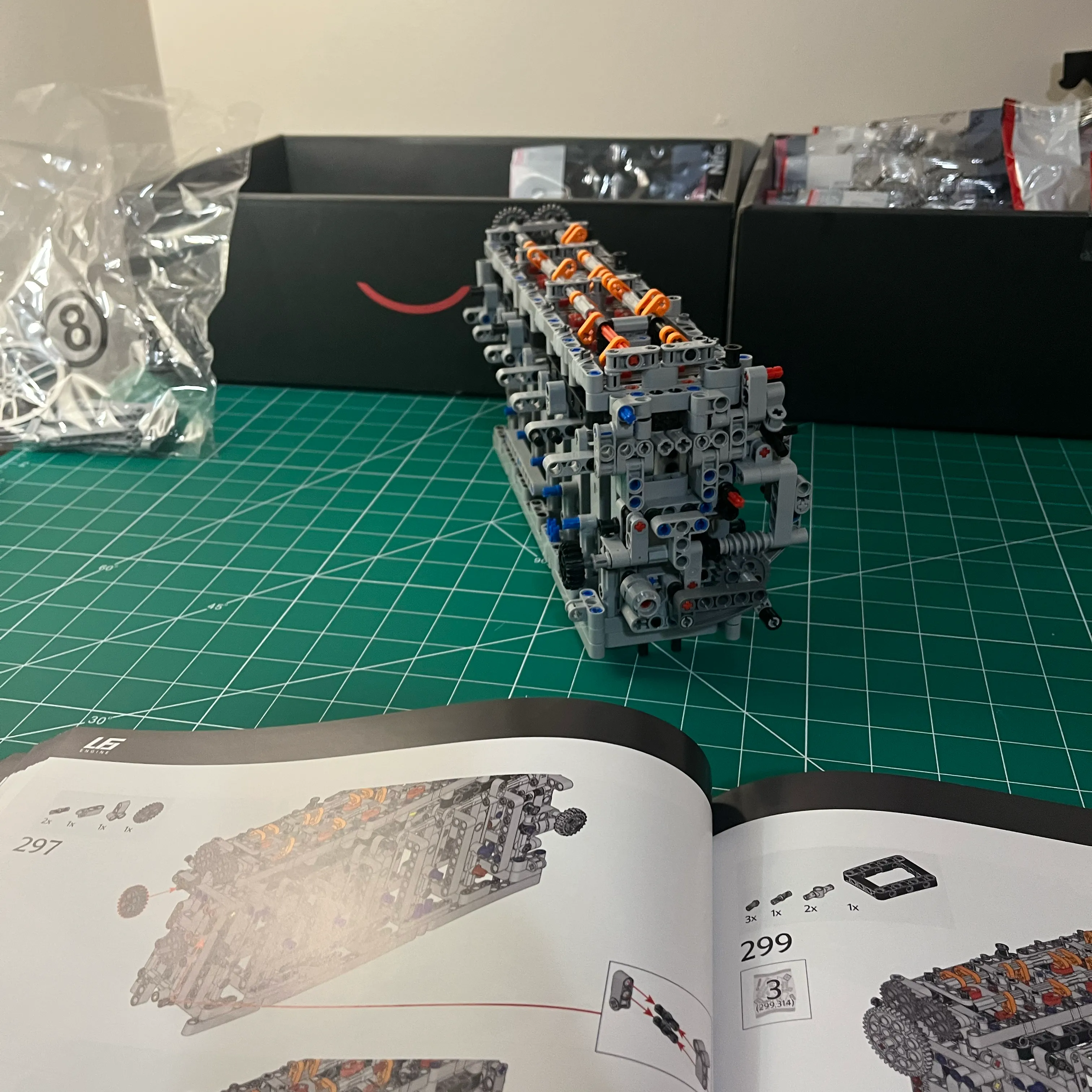
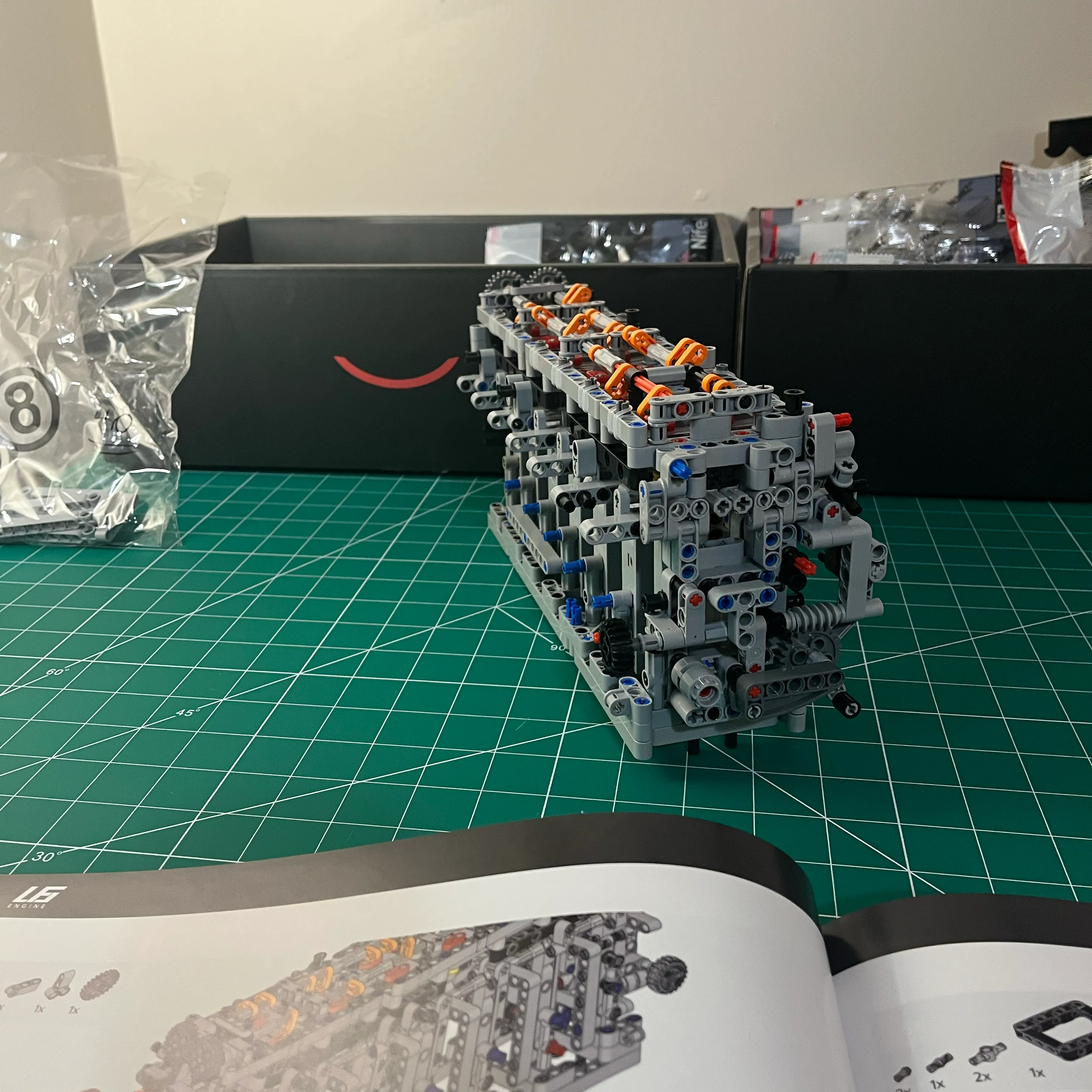
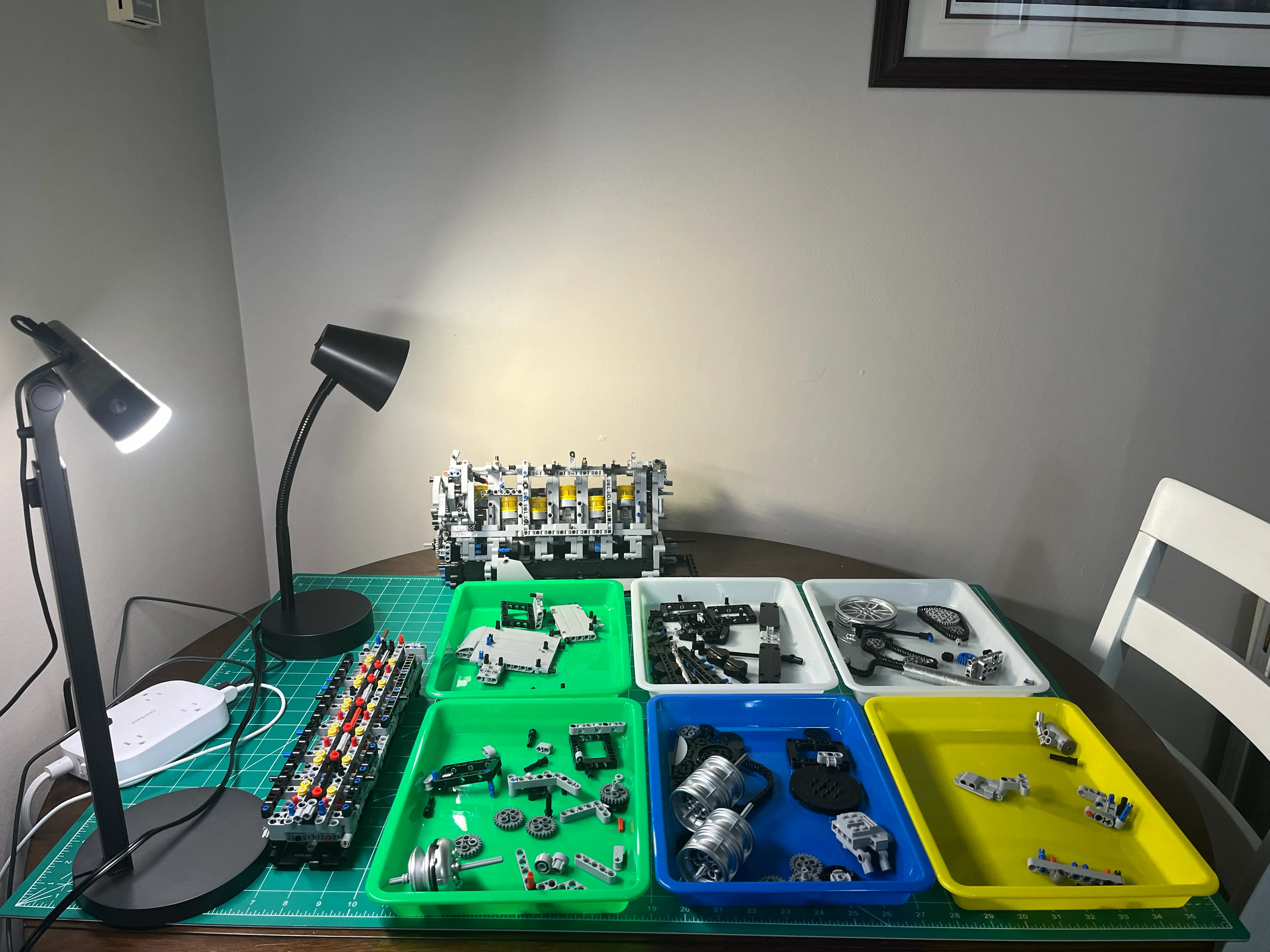
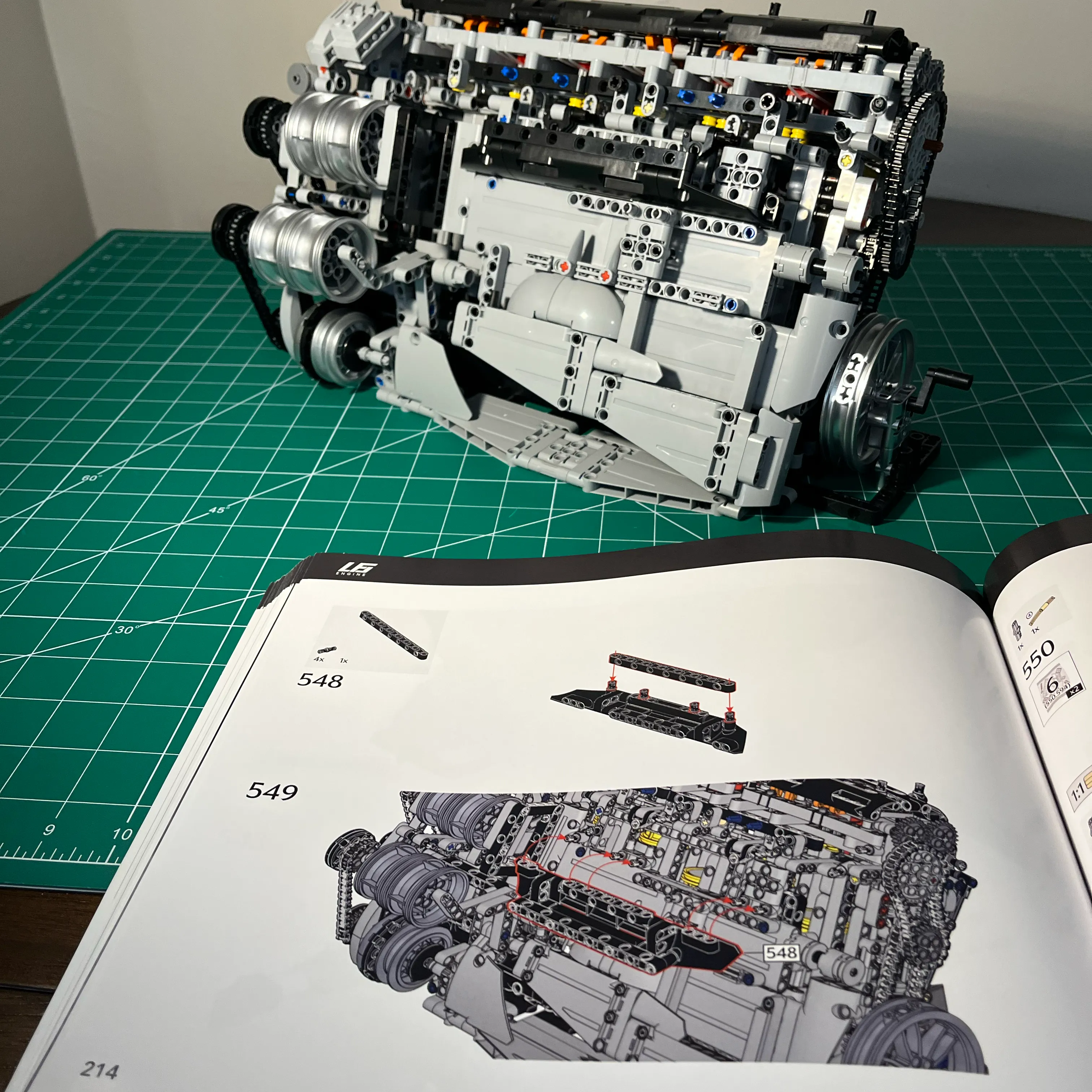
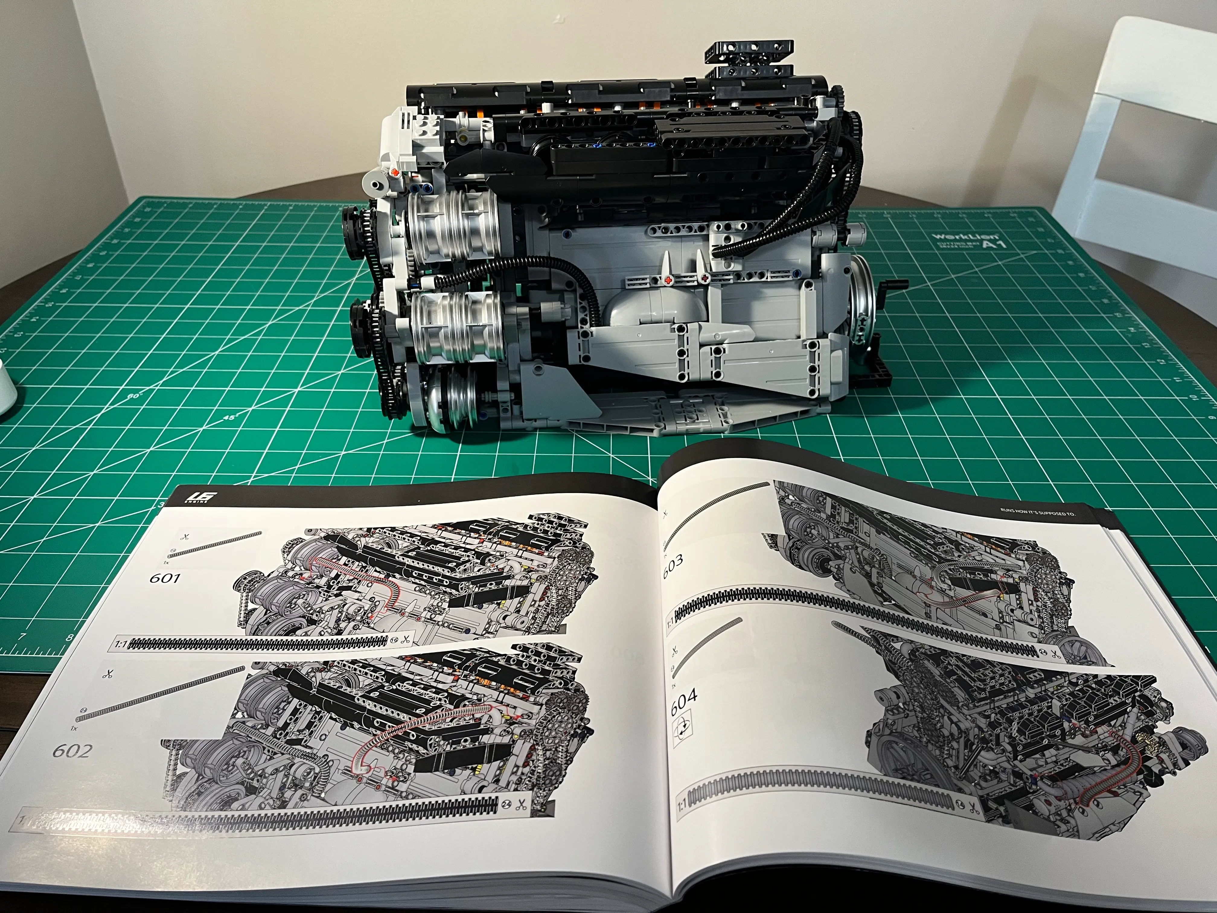
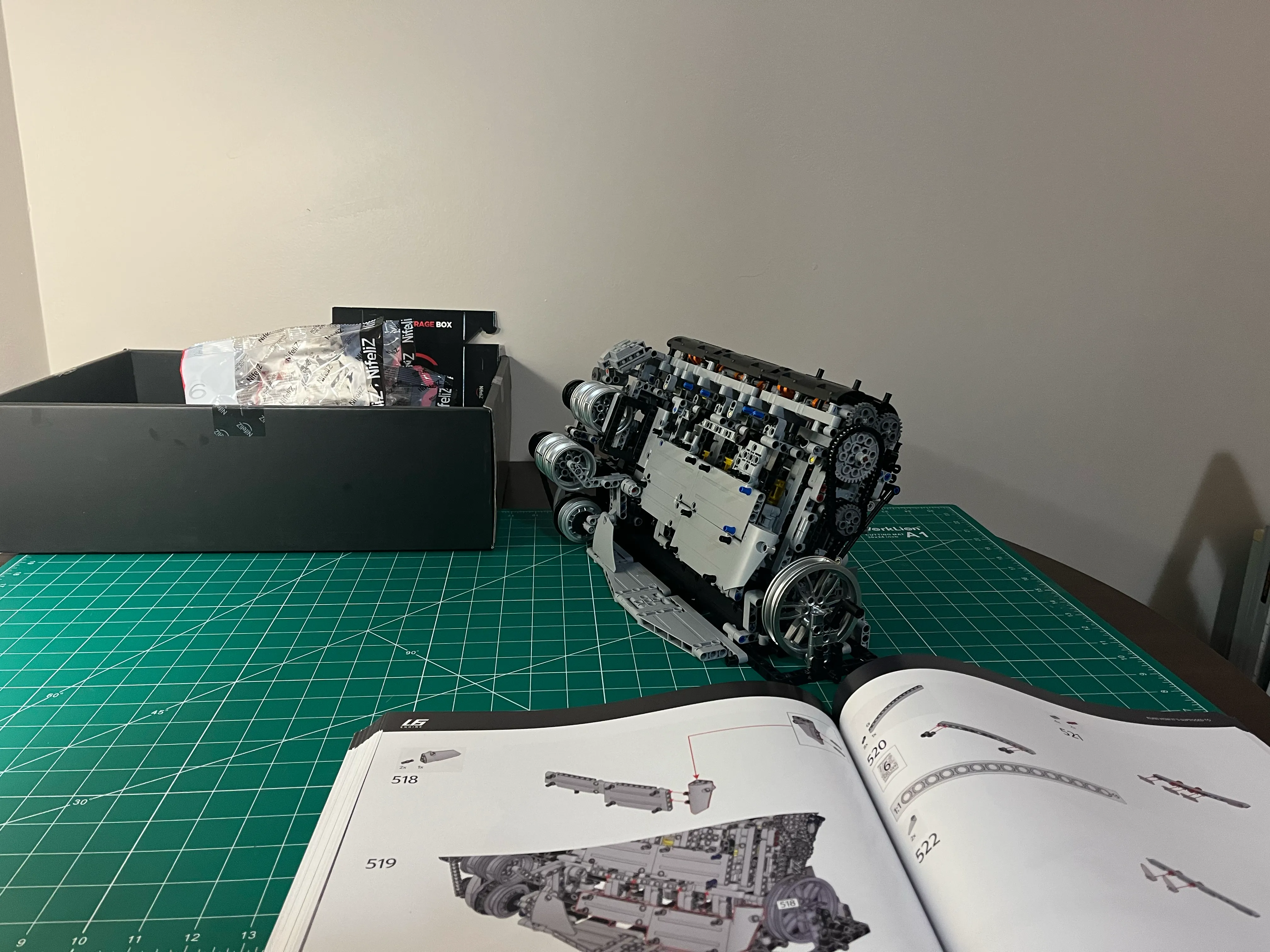
Build Progress